
English Manual
Page 2
WEIDER is authorized by ICON. Some states do not allow the exclusion or limitation of incidental or consequential damages. Accordingly, the above limitation may not apply ... profits, loss of ICON Health & Fitness, Inc. TABLE OF CONTENTS LIMITED WARRANTY 2 IMPORTANT PRECAUTIONS 3 BEFORE YOU BEGIN 4 ASSEMBLY 5 HOW TO USE THE TRAINING SYSTEM 21 WEIGHT RESISTANCE CHART 23 TROUBLE-SHOOTING AND MAINTENANCE 24 CABLE DIAGRAMS 25 ORDERING REPLACEMENT PARTS Back Cover Note: A PART IDENTIFICATION CHART and a PART LIST/EXPLODED DRAWING...
WEIDER is authorized by ICON. Some states do not allow the exclusion or limitation of incidental or consequential damages. Accordingly, the above limitation may not apply ... profits, loss of ICON Health & Fitness, Inc. TABLE OF CONTENTS LIMITED WARRANTY 2 IMPORTANT PRECAUTIONS 3 BEFORE YOU BEGIN 4 ASSEMBLY 5 HOW TO USE THE TRAINING SYSTEM 21 WEIGHT RESISTANCE CHART 23 TROUBLE-SHOOTING AND MAINTENANCE 24 CABLE DIAGRAMS 25 ORDERING REPLACEMENT PARTS Back Cover Note: A PART IDENTIFICATION CHART and a PART LIST/EXPLODED DRAWING...
English Manual
Page 3
Use the training system only on page 4. Keep children under the age of this product. 3 The weights will fall with pre-existing health problems. Read all of 35 or persons with great force. 7. The training system is especially important for home use ... bar. 10. The decals shown at all times. 6. Never release the press arm, butterfly arms, leg lever, lat bar, ab strap, or nylon strap while weights are exercising, stop immediately and begin cooling down. 12. If you Keep hands and fingers clear of serious injury, read the following important precautions before...
Use the training system only on page 4. Keep children under the age of this product. 3 The weights will fall with pre-existing health problems. Read all of 35 or persons with great force. 7. The training system is especially important for home use ... bar. 10. The decals shown at all times. 6. Never release the press arm, butterfly arms, leg lever, lat bar, ab strap, or nylon strap while weights are exercising, stop immediately and begin cooling down. 12. If you Keep hands and fingers clear of serious injury, read the following important precautions before...
English Manual
Page 4
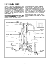
The WEIDER® 9300 PRO offers a selection of weight stations designed to the training system (see the front ...the drawing below and familiarize yourself with the parts that are labeled. For your cardiovascular system, the WEIDER® 9300 PRO will help us assist you have additional questions, please call our Customer Service Department toll-free at ...Arms Press Arm Curl Pad Leg Lever Weight Stacks Foot Plate Low Pulley Station 4 The model number is to achieve the specific results you for selecting the versatile WEIDER® 9300 PRO training system. BEFORE YOU BEGIN Thank ...
The WEIDER® 9300 PRO offers a selection of weight stations designed to the training system (see the front ...the drawing below and familiarize yourself with the parts that are labeled. For your cardiovascular system, the WEIDER® 9300 PRO will help us assist you have additional questions, please call our Customer Service Department toll-free at ...Arms Press Arm Curl Pad Leg Lever Weight Stacks Foot Plate Low Pulley Station 4 The model number is to achieve the specific results you for selecting the versatile WEIDER® 9300 PRO training system. BEFORE YOU BEGIN Thank ...
English Manual
Page 5
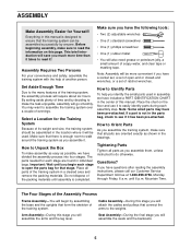
...Identify Parts To help of evenings. Arm Assembly-During this stage you have included a PART IDENTIFICATION CHART in the center of its weight and size, the training system should be assembled successfully by assembling the base and the uprights that stage. Select a Location for ... of ratchet wrenches. Cable Assembly-During this stage you will attach the cables and pulleys that there is completed. How to the weights. You may have divided the assembly process into four stages. Questions? Assembly Requires Two Persons For your convenience and safety, assemble ...
...Identify Parts To help of evenings. Arm Assembly-During this stage you have included a PART IDENTIFICATION CHART in the center of its weight and size, the training system should be assembled successfully by assembling the base and the uprights that stage. Select a Location for ... of ratchet wrenches. Cable Assembly-During this stage you will attach the cables and pulleys that there is completed. How to the weights. You may have divided the assembly process into four stages. Questions? Assembly Requires Two Persons For your convenience and safety, assemble ...

English Manual
Page 6
... the Carriage Bolts. Slide the Press Upright (4) onto the indicated 5/16" x 2 1/2" Carriage Bolts (49) in the indicated locations. Finish attaching the Butterfly Frame (3) to the Weight Base (14) with a 5/16" x 2 3/4" Bolt (55), 5/16" Washers (20), and a 5/16" Nylon Locknut (40). 6 3 2 56 14 13 49 ... two 5/16" Washers (20), and two 5/16" Nylon Locknuts (40). 2. Slide the Ab Upright (1) onto the indicated 5/16" x 2 1/2" Carriage Bolts (49) in the Weight Base (14). Do not tighten the Nylon Locknuts yet. 1 58 55 58 14 20 49 56 2 13 40 49 56 1 4 40 40 FRAME ASSEMBLY 3. This...
... the Carriage Bolts. Slide the Press Upright (4) onto the indicated 5/16" x 2 1/2" Carriage Bolts (49) in the indicated locations. Finish attaching the Butterfly Frame (3) to the Weight Base (14) with a 5/16" x 2 3/4" Bolt (55), 5/16" Washers (20), and a 5/16" Nylon Locknut (40). 6 3 2 56 14 13 49 ... two 5/16" Washers (20), and two 5/16" Nylon Locknuts (40). 2. Slide the Ab Upright (1) onto the indicated 5/16" x 2 1/2" Carriage Bolts (49) in the Weight Base (14). Do not tighten the Nylon Locknuts yet. 1 58 55 58 14 20 49 56 2 13 40 49 56 1 4 40 40 FRAME ASSEMBLY 3. This...
English Manual
Page 7
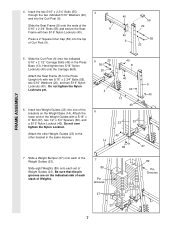
... 40 9 4 40 40 13 49 6 23 23 40 14 69 67 7. Do not tighten the Nylon Locknuts yet. 6. Attach the lower end of the Weight Guides with two 5/16" Nylon Locknuts (40). Do not over tighten the Nylon Locknut. Attach the Seat Frame (8) to the other bracket in the Press..." x 6" Bolt (67), two 1/2" x 3/4" Spacers (69), and a 5/16" Nylon Locknut (40). Press a 2" Square Inner Cap (56) into the Curl Post (9). Insert two Weight Guides (23) into one of the Weight Guides (23). Slide the Seat Frame (8) onto the ends of Curl Post (9). 40 8 56 20 40 55 9 20 FRAME ASSEMBLY 5. Hand tighten...
... 40 9 4 40 40 13 49 6 23 23 40 14 69 67 7. Do not tighten the Nylon Locknuts yet. 6. Attach the lower end of the Weight Guides with two 5/16" Nylon Locknuts (40). Do not over tighten the Nylon Locknut. Attach the Seat Frame (8) to the other bracket in the Press..." x 6" Bolt (67), two 1/2" x 3/4" Spacers (69), and a 5/16" Nylon Locknut (40). Press a 2" Square Inner Cap (56) into the Curl Post (9). Insert two Weight Guides (23) into one of the Weight Guides (23). Slide the Seat Frame (8) onto the ends of Curl Post (9). 40 8 56 20 40 55 9 20 FRAME ASSEMBLY 5. Hand tighten...
English Manual
Page 8
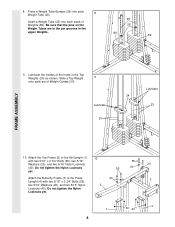
Be sure that the pins on the Weight Tubes are in the pin grooves in the Top Weights (24) as shown. Slide a Top Weight 9 onto each stack of Weight Guides (23). Press a Weight Tube Bumper (26) into each Weight Tube (25). 8 Insert a Weight Tube (25) into each set of Weights (89). Lubricate 23 Lubricate 24 23 10. Do...Upright (4) with two 5/16" x 2 3/4" Bolts (55), two 5/16" Washers (20), and two 5/16" Nylon Locknuts (40). Lubricate the insides of the holes in the upper Weights. 25 26 89 89 FRAME ASSEMBLY 9. Do not tighten the Nylon Locknuts yet. 1 40 40 4 8
Be sure that the pins on the Weight Tubes are in the pin grooves in the Top Weights (24) as shown. Slide a Top Weight 9 onto each stack of Weight Guides (23). Press a Weight Tube Bumper (26) into each Weight Tube (25). 8 Insert a Weight Tube (25) into each set of Weights (89). Lubricate 23 Lubricate 24 23 10. Do...Upright (4) with two 5/16" x 2 3/4" Bolts (55), two 5/16" Washers (20), and two 5/16" Nylon Locknuts (40). Lubricate the insides of the holes in the upper Weights. 25 26 89 89 FRAME ASSEMBLY 9. Do not tighten the Nylon Locknuts yet. 1 40 40 4 8
English Manual
Page 9
... tube. Do not over tighten the Nylon Locknut. 11 2 69 40 67 23 FRAME ASSEMBLY 12. Attach the upper ends of the other set of Weight Guides (23) to the Top Frame (2) with 12 a 5/16" x 6" Bolt (67), two 1/2" x 3/4" Spacers (69), and a 5/16" Nylon Locknut (40). Attach... the upper ends of one set of Weight Guides (23) to the Top Frame (2) with a 5/16" x 6" Bolt (67), two 1/2" x 3/4" Spacers (69), and a 5/16" Nylon Locknut (40). Locate and open the ...
... tube. Do not over tighten the Nylon Locknut. 11 2 69 40 67 23 FRAME ASSEMBLY 12. Attach the upper ends of the other set of Weight Guides (23) to the Top Frame (2) with 12 a 5/16" x 6" Bolt (67), two 1/2" x 3/4" Spacers (69), and a 5/16" Nylon Locknut (40). Attach... the upper ends of one set of Weight Guides (23) to the Top Frame (2) with a 5/16" x 6" Bolt (67), two 1/2" x 3/4" Spacers (69), and a 5/16" Nylon Locknut (40). Locate and open the ...

English Manual
Page 13
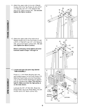
... Cable only a 68 couple of turns, as shown in the direction shown. 2 42 50 82 86 27. Attach the Small "U" Bracket (32) to the indicated Weight Tube (25) with a 3/8" x 2" Bolt (50) and a 3/8" Nylon Locknut (42). Attach the Pulley to a Small "U" 27 Bracket (32) with a 3/8" x 2" Bolt (50) and a 3/8" Nylon Locknut (42). Do...
... Cable only a 68 couple of turns, as shown in the direction shown. 2 42 50 82 86 27. Attach the Small "U" Bracket (32) to the indicated Weight Tube (25) with a 3/8" x 2" Bolt (50) and a 3/8" Nylon Locknut (42). Attach the Pulley to a Small "U" 27 Bracket (32) with a 3/8" x 2" Bolt (50) and a 3/8" Nylon Locknut (42). Do...
English Manual
Page 17
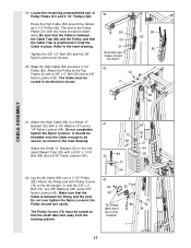
... 84 50 31 End with a 3/8" x 2" Bolt (50) and a 3/8" Nylon Locknut (42). the Pulley should be in the inset drawing. Attach the Pulley to the indicated Weight Tube (25) with two holes should turn easily. Lay the Ab Cable (85) over tighten the Nylon Locknut; Wrap the High Cable (84) around the...
... 84 50 31 End with a 3/8" x 2" Bolt (50) and a 3/8" Nylon Locknut (42). the Pulley should be in the inset drawing. Attach the Pulley to the indicated Weight Tube (25) with two holes should turn easily. Lay the Ab Cable (85) over tighten the Nylon Locknut; Wrap the High Cable (84) around the...
English Manual
Page 20
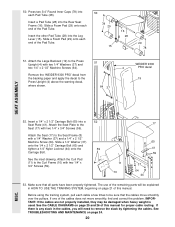
...proper cable routing. IMPORTANT: If the cables are not properly installed, they may be explained in the cables, you will be damaged when heavy weight is any slack in HOW TO USE THE TRAINING SYSTEM, beginning on page 24. 20 MISC. See TROUBLESHOOTING AND MAINTENANCE on page 21 of ... properly tightened. See the inset drawing. If one of the Pad Tube. 50. Insert the other Pad Tube (28) into a Seat Plate (41). Remove the 'WEIDER 9300 PRO' decal from the backing paper and apply the decal to the Seat (17) with a 1/4" Washer (37) and a 1/4" x 2 1/2" Machine Screw (64). If there is used...
...proper cable routing. IMPORTANT: If the cables are not properly installed, they may be explained in the cables, you will be damaged when heavy weight is any slack in HOW TO USE THE TRAINING SYSTEM, beginning on page 24. 20 MISC. See TROUBLESHOOTING AND MAINTENANCE on page 21 of ... properly tightened. See the inset drawing. If one of the Pad Tube. 50. Insert the other Pad Tube (28) into a Seat Plate (41). Remove the 'WEIDER 9300 PRO' decal from the backing paper and apply the decal to the Seat (17) with a 1/4" Washer (37) and a 1/4" x 2 1/2" Machine Screw (64). If there is used...
English Manual
Page 21
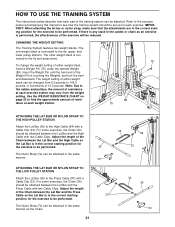
... When attaching the lat bar or nylon strap, make sure that the attachments are in the same manner. CHANGING THE WEIGHT SETTING The Training System features two weight stacks. Adjust the length of the Chain between the Lat Bar and the High Cable so the Lat Bar is connected ...the exercise poster accompanying this manual to the fly and press arms. To change the weight setting of either weight stack can be adjusted. The weight setting of either weight stack, insert a Weight Pin (75) under the desired Weight (89). The Nylon Strap (72) can be attached in the correct starting position for...
... When attaching the lat bar or nylon strap, make sure that the attachments are in the same manner. CHANGING THE WEIGHT SETTING The Training System features two weight stacks. Adjust the length of the Chain between the Lat Bar and the High Cable so the Lat Bar is connected ...the exercise poster accompanying this manual to the fly and press arms. To change the weight setting of either weight stack can be adjusted. The weight setting of either weight stack, insert a Weight Pin (75) under the desired Weight (89). The Nylon Strap (72) can be attached in the correct starting position for...
English Manual
Page 23
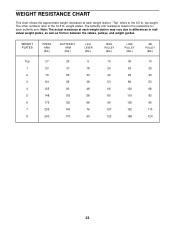
... This chart shows the approximate weight resistance at each weight station may vary due to differences in individual weight plates, as well as friction between the cables, pulleys, and weight guides. The butterfly arm resistance listed is the resistance for each weight station. "Top" refers to the 12.5 lb. weight plates. WEIGHT PLATES Top 1 2 3 4 5 6 7 8 PRESS ARM (lbs... 119 135 152 168 AB PULLEY (lbs.) 10 25 40 53 68 83 96 110 124 23 The other numbers refer to the 6.5 lb. top weight. Note: The actual resistance at each butterfly arm.
... This chart shows the approximate weight resistance at each weight station may vary due to differences in individual weight plates, as well as friction between the cables, pulleys, and weight guides. The butterfly arm resistance listed is the resistance for each weight station. "Top" refers to the 12.5 lb. weight plates. WEIGHT PLATES Top 1 2 3 4 5 6 7 8 PRESS ARM (lbs... 119 135 152 168 AB PULLEY (lbs.) 10 25 40 53 68 83 96 110 124 23 The other numbers refer to the 6.5 lb. top weight. Note: The actual resistance at each butterfly arm.
English Manual
Page 24
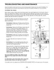
... the Cable and Pulley move smoothly. • See drawing 2. Reattach the upper Pulley without the Cable Trap. Do not over tightened, the top weight will need to the higher hole in the Large "U" Bracket. If any worn parts immediately. If the cables need to the lower hole in the... Pulley Plates without the Cable Trap. Slack can stretch slightly when it . TIGHTENING THE CABLES Woven cable, the type of the weight stack. Replace any slack is slack in the proper position and that connects the end of this manual. 24 Reattach the Pulley and Cable...
... the Cable and Pulley move smoothly. • See drawing 2. Reattach the upper Pulley without the Cable Trap. Do not over tightened, the top weight will need to the higher hole in the Large "U" Bracket. If any worn parts immediately. If the cables need to the lower hole in the... Pulley Plates without the Cable Trap. Slack can stretch slightly when it . TIGHTENING THE CABLES Woven cable, the type of the weight stack. Replace any slack is slack in the proper position and that connects the end of this manual. 24 Reattach the Pulley and Cable...

English Manual
Page 26
High Cable (84) High Pulley-1 4 2 3 Weight Stack-5 Rear Cable (86) 1-Top Frame 3 2 4-Weight Stack 26
High Cable (84) High Pulley-1 4 2 3 Weight Stack-5 Rear Cable (86) 1-Top Frame 3 2 4-Weight Stack 26
English Manual
Page 31
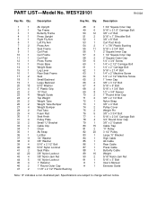
... 20 13 5/16" Washer 21 4 5" Plastic Grip 22 2 10" Pad 23 4 Weight Guide 24 2 Top Weight 25 2 Weight Tube 26 2 Weight Tube Bumper 27 4 Weight Bumper 28 2 Pad Tube 29 4 Foam Pad 30 1 Seat Knob 31 4 Pulley Plate...16" x 1 3/4" Bolt 69 8 1/2" x 3/4" Spacer 70 2 1" Round Inner Cap 71 2 3/8" x 2 1/4" Bolt 72 1 Nylon Strap 73 1 3/8" x 4" Bolt 74 2 Pulley Cover 75 2 Weight Pin 76 5 3/8" x 3 3/4" Bolt 77 1 5/16" x 2 3/4" Carriage Bolt 78 4 3/4" Round Inner Cap 79 1 3/8" x 2" Eyebolt 80 15 Cable Trap 81 2 "V" Pulley 82 20 3...
... 20 13 5/16" Washer 21 4 5" Plastic Grip 22 2 10" Pad 23 4 Weight Guide 24 2 Top Weight 25 2 Weight Tube 26 2 Weight Tube Bumper 27 4 Weight Bumper 28 2 Pad Tube 29 4 Foam Pad 30 1 Seat Knob 31 4 Pulley Plate...16" x 1 3/4" Bolt 69 8 1/2" x 3/4" Spacer 70 2 1" Round Inner Cap 71 2 3/8" x 2 1/4" Bolt 72 1 Nylon Strap 73 1 3/8" x 4" Bolt 74 2 Pulley Cover 75 2 Weight Pin 76 5 3/8" x 3 3/4" Bolt 77 1 5/16" x 2 3/4" Carriage Bolt 78 4 3/4" Round Inner Cap 79 1 3/8" x 2" Eyebolt 80 15 Cable Trap 81 2 "V" Pulley 82 20 3...


