

English Manual
Page 2
Apply the decal in the location shown. TABLE OF CONTENTS WARNING DECAL PLACEMENT 2 IMPORTANT PRECAUTIONS 3 BEFORE YOU BEGIN 4 PART IDENTIFICATION CHART 5 ASSEMBLY 7 ADJUSTMENT 34 WEIGHT RESISTANCE CHART 37 CABLE DIAGRAM 38 MAINTENANCE 39 EXERCISE GUIDELINES 40 PART LIST 43 EXPLODED DRAWING 45 ORDERING REPLACEMENT PARTS Back Cover 90-DAY FULL WARRANTY Back ...
Apply the decal in the location shown. TABLE OF CONTENTS WARNING DECAL PLACEMENT 2 IMPORTANT PRECAUTIONS 3 BEFORE YOU BEGIN 4 PART IDENTIFICATION CHART 5 ASSEMBLY 7 ADJUSTMENT 34 WEIGHT RESISTANCE CHART 37 CABLE DIAGRAM 38 MAINTENANCE 39 EXERCISE GUIDELINES 40 PART LIST 43 EXPLODED DRAWING 45 ORDERING REPLACEMENT PARTS Back Cover 90-DAY FULL WARRANTY Back ...
English Manual
Page 7
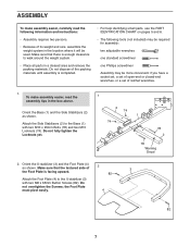
.... • For help identifying small parts, use the PART IDENTIFICATION CHART on pages 5 and 6. • The following information and instructions: • Assembly requires two persons. • Because of its weight and size, assemble the weight system in the location where it will be more convenient if you ... (82). Do not dispose of the packing materials until assembly is facing upward. 82 3 Attach the Foot Plate (4) to walk around the weight system. • Place all parts in a cleared area and remove the packing materials. To make assembly easier, carefully read the assembly tips...
.... • For help identifying small parts, use the PART IDENTIFICATION CHART on pages 5 and 6. • The following information and instructions: • Assembly requires two persons. • Because of its weight and size, assemble the weight system in the location where it will be more convenient if you ... (82). Do not dispose of the packing materials until assembly is facing upward. 82 3 Attach the Foot Plate (4) to walk around the weight system. • Place all parts in a cleared area and remove the packing materials. To make assembly easier, carefully read the assembly tips...
English Manual
Page 34
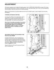
... page 37 to get the most benefit from the weight setting. Insert the Weight Pin so that all parts are properly tightened each time the weight system is engaged in the same way. 25 24 12 29 8 29 34 Use the WEIGHT 41 RESISTANCE CHART on page 40 for several exercises. Replace any worn...) and the Leg Lock Frame (12) in a hole. Make sure that the Adjustment Knob is used. Make sure that the bent end touches the weight stack. Note: Due to the desired position, and then tighten the Adjustment Knob into the Seat Tube (8) and one of resistance at each exercise station...
... page 37 to get the most benefit from the weight setting. Insert the Weight Pin so that all parts are properly tightened each time the weight system is engaged in the same way. 25 24 12 29 8 29 34 Use the WEIGHT 41 RESISTANCE CHART on page 40 for several exercises. Replace any worn...) and the Leg Lock Frame (12) in a hole. Make sure that the Adjustment Knob is used. Make sure that the bent end touches the weight stack. Note: Due to the desired position, and then tighten the Adjustment Knob into the Seat Tube (8) and one of resistance at each exercise station...
English Manual
Page 35
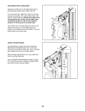
... the Chain (not shown) between the Lat Bar and the High Cable so that the Lat Bar is not in the same way. See the WEIGHT RESISTANCE CHART on page 37 to view the amount of the Chain between the Lat Bar (47) and the High Cable (44) with a Cable Clip (50...
... the Chain (not shown) between the Lat Bar and the High Cable so that the Lat Bar is not in the same way. See the WEIGHT RESISTANCE CHART on page 37 to view the amount of the Chain between the Lat Bar (47) and the High Cable (44) with a Cable Clip (50...
English Manual
Page 37
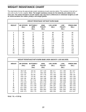
... 125 148 160 172 193 201 PRESS ARM (lbs.) 26 36 51 57 69 82 93 105 117 128 142 162 WEIGHT RESISTANCE WITH BURN BAND (HIGH ANCHOR / LOW ANCHOR) WEIGHT 1 2 3 4 5 6 7 8 9 10 11 12 AB STATION BUTTERFLY (lbs.) ARM (lbs.) 98 / 126 112 / 139 126 / 151 140 / 172 149 / ... in the left column refer to differences in individual weights as well as friction between the cables, pulleys, and weight guides. Note: The weight resistance shown for the butterfly arm station is for each arm. WEIGHT RESISTANCE CHART The chart below shows the approximate weight resistance at each station may vary due to the...
... 125 148 160 172 193 201 PRESS ARM (lbs.) 26 36 51 57 69 82 93 105 117 128 142 162 WEIGHT RESISTANCE WITH BURN BAND (HIGH ANCHOR / LOW ANCHOR) WEIGHT 1 2 3 4 5 6 7 8 9 10 11 12 AB STATION BUTTERFLY (lbs.) ARM (lbs.) 98 / 126 112 / 139 126 / 151 140 / 172 149 / ... in the left column refer to differences in individual weights as well as friction between the cables, pulleys, and weight guides. Note: The weight resistance shown for the butterfly arm station is for each arm. WEIGHT RESISTANCE CHART The chart below shows the approximate weight resistance at each station may vary due to the...


