
English Manual
Page 1
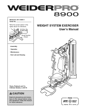
Keep this equipment. Serial Number Decal WEIGHT SYSTEM EXERCISER Userʼs Manual • Assembly • Operation • Maintenance • Part List and Drawing Sears, Roebuck and Co. Model No. 831.14923.1 Serial No. Write the serial number in this manual before using this manual for reference. Hoffman Estates, IL 60179 CAUTION Read all precautions and instructions in the space above for future reference.
Keep this equipment. Serial Number Decal WEIGHT SYSTEM EXERCISER Userʼs Manual • Assembly • Operation • Maintenance • Part List and Drawing Sears, Roebuck and Co. Model No. 831.14923.1 Serial No. Write the serial number in this manual before using this manual for reference. Hoffman Estates, IL 60179 CAUTION Read all precautions and instructions in the space above for future reference.

English Manual
Page 2
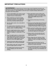
Apply the decal in the location shown. Note: The decal(s) may not be shown at actual size. 2 TABLE OF CONTENTS WARNING DECAL PLACEMENT 2 IMPORTANT PRECAUTIONS 3 BEFORE YOU BEGIN 4 PART IDENTIFICATION CHART 5 ASSEMBLY 7 ADJUSTMENT 34 WEIGHT RESISTANCE CHART 37 CABLE DIAGRAM 38 MAINTENANCE 39 EXERCISE GUIDELINES 40 PART LIST 43 EXPLODED DRAWING 45 ORDERING REPLACEMENT PARTS Back Cover 90-DAY FULL WARRANTY Back Cover WARNING DECAL PLACEMENT This drawing shows the location(s) of the warning decal(s). If a decal is missing or illegible, call 1-877-992-5999 and request a free ...
Apply the decal in the location shown. Note: The decal(s) may not be shown at actual size. 2 TABLE OF CONTENTS WARNING DECAL PLACEMENT 2 IMPORTANT PRECAUTIONS 3 BEFORE YOU BEGIN 4 PART IDENTIFICATION CHART 5 ASSEMBLY 7 ADJUSTMENT 34 WEIGHT RESISTANCE CHART 37 CABLE DIAGRAM 38 MAINTENANCE 39 EXERCISE GUIDELINES 40 PART LIST 43 EXPLODED DRAWING 45 ORDERING REPLACEMENT PARTS Back Cover 90-DAY FULL WARRANTY Back Cover WARNING DECAL PLACEMENT This drawing shows the location(s) of the warning decal(s). If a decal is missing or illegible, call 1-877-992-5999 and request a free ...
English Manual
Page 3
Before beginning any worn parts immediately. 8. Use the weight system only as described in this product. 1. Make sure that there is intended for personal injury or property damage sustained by persons weighing more than 300 lbs. (136 kg). 12. This is the responsibility of the owner to ensure that could become caught on the pulleys at all times. 9. Do not put the weight system in serious injury or death. Always secure the weight stack with pre-existing health problems. 10. Never release the arms, leg lever, lat bar, handle, ankle strap, or double strap while ...
Before beginning any worn parts immediately. 8. Use the weight system only as described in this product. 1. Make sure that there is intended for personal injury or property damage sustained by persons weighing more than 300 lbs. (136 kg). 12. This is the responsibility of the owner to ensure that could become caught on the pulleys at all times. 9. Do not put the weight system in serious injury or death. Always secure the weight stack with pre-existing health problems. 10. Never release the arms, leg lever, lat bar, handle, ankle strap, or double strap while ...
English Manual
Page 4
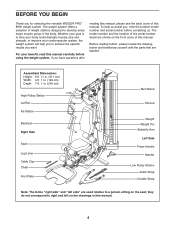
... YOU BEGIN Thank you have questions after reading this manual, please see the back cover of this manual. If you for selecting the versatile WEIDER PRO™ 8900 weight system. The model number and the location of the body. For your goal is to develop every major muscle group of the serial number...
... YOU BEGIN Thank you have questions after reading this manual, please see the back cover of this manual. If you for selecting the versatile WEIDER PRO™ 8900 weight system. The model number and the location of the body. For your goal is to develop every major muscle group of the serial number...

English Manual
Page 5
The number in assembly. To avoid damaging parts, do not use power tools for assembly. If a part is the key number of the part, from the PART LIST near the end of this manual. PART IDENTIFICATION CHART Refer to the drawings below to see if it has been preassembled. ST4.2 x 19mm Screw (90) 6.35mm Spacer (94) 12.7mm Spacer (73) 14.8mm Spacer (95) M10 Washer (88) M4 Locknut (108) M6 Locknut (87) M10 Jam Nut (99) M10 Locknut (74) Continued on page 6 M10 Curved Washer (86) 5 IMPORTANT: If you cannot find a part in the hardware kit, check to identify small parts used in ...
The number in assembly. To avoid damaging parts, do not use power tools for assembly. If a part is the key number of the part, from the PART LIST near the end of this manual. PART IDENTIFICATION CHART Refer to the drawings below to see if it has been preassembled. ST4.2 x 19mm Screw (90) 6.35mm Spacer (94) 12.7mm Spacer (73) 14.8mm Spacer (95) M10 Washer (88) M4 Locknut (108) M6 Locknut (87) M10 Jam Nut (99) M10 Locknut (74) Continued on page 6 M10 Curved Washer (86) 5 IMPORTANT: If you cannot find a part in the hardware kit, check to identify small parts used in ...
English Manual
Page 7
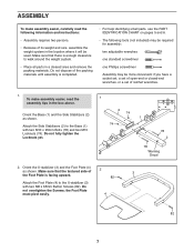
Make sure that there is facing upward. 82 3 Attach the Foot Plate (4) to the U-stabilizer (3) with two M10 x 95mm Bolts (78) and two M10 Locknuts (74). Orient the Base (1) and the Side Stabilizers (2) as shown. Do not fully tighten the Locknuts yet. 1 2 74 74 1 78 2 78 Warning Decal 2. the Foot Plate must pivot easily. 4 82 7 Attach the Side Stabilizers (2) to walk around the weight system. • Place all parts in a cleared area and remove the packing materials. Do not overtighten the Screws; To make assembly easier, carefully read the assembly tips in the ...
Make sure that there is facing upward. 82 3 Attach the Foot Plate (4) to the U-stabilizer (3) with two M10 x 95mm Bolts (78) and two M10 Locknuts (74). Orient the Base (1) and the Side Stabilizers (2) as shown. Do not fully tighten the Locknuts yet. 1 2 74 74 1 78 2 78 Warning Decal 2. the Foot Plate must pivot easily. 4 82 7 Attach the Side Stabilizers (2) to walk around the weight system. • Place all parts in a cleared area and remove the packing materials. Do not overtighten the Screws; To make assembly easier, carefully read the assembly tips in the ...

English Manual
Page 8
Attach the U-stabilizer (3) to the Base (1) and the Side Stabilizers (2) with two M10 x 68mm Bolts (66), two M10 Washers 3 (88), and two M10 Locknuts (74). 3 74 1 74 88 66 88 4. Orient the Upright (5) as shown. 4 Attach the Upright (5) to the Base (1) with four M10 x 55mm Bolts (79), four M10 Washers (88), and four M10 Locknuts (74). Do not fully tighten the Locknuts yet. 5 74 74 74 2 2 1 88 88 79 79 8 3.
Attach the U-stabilizer (3) to the Base (1) and the Side Stabilizers (2) with two M10 x 68mm Bolts (66), two M10 Washers 3 (88), and two M10 Locknuts (74). 3 74 1 74 88 66 88 4. Orient the Upright (5) as shown. 4 Attach the Upright (5) to the Base (1) with four M10 x 55mm Bolts (79), four M10 Washers (88), and four M10 Locknuts (74). Do not fully tighten the Locknuts yet. 5 74 74 74 2 2 1 88 88 79 79 8 3.

English Manual
Page 9
Orient the Seat Tube (8) as shown. 5 Attach the Leg (10) to the Upright (5) with two M10 x 93mm Bolts (63), two M10 Washers (88), and two M10 Locknuts (74). Attach the Leg (10) to the Seat Tube (8) with two 10 M10 x 55mm Bolts (79), two M10 Washers (88), and two M10 Locknuts (74). Do not fully tighten the Locknuts yet. 5. See steps 1, 4, 5, and 6. Tighten the M10 Locknuts (74). 6 74 74 8 10 74 88 74 5 88 63 66 88 9 Orient the Leg (10) as shown. Attach the Seat Tube (8) to the Base (1) with two M10 x 68mm Bolts (66), two M10 Washers (88), and two M10 Locknuts (74...
Orient the Seat Tube (8) as shown. 5 Attach the Leg (10) to the Upright (5) with two M10 x 93mm Bolts (63), two M10 Washers (88), and two M10 Locknuts (74). Attach the Leg (10) to the Seat Tube (8) with two 10 M10 x 55mm Bolts (79), two M10 Washers (88), and two M10 Locknuts (74). Do not fully tighten the Locknuts yet. 5. See steps 1, 4, 5, and 6. Tighten the M10 Locknuts (74). 6 74 74 8 10 74 88 74 5 88 63 66 88 9 Orient the Leg (10) as shown. Attach the Seat Tube (8) to the Base (1) with two M10 x 68mm Bolts (66), two M10 Washers (88), and two M10 Locknuts (74...
English Manual
Page 10
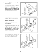
Attach the Leg Lever (13) to identify the cables as shown. See the CABLE DIAGRAM on the Leg. 80 13 Grease 80 10 High End 8. Make sure that the high end of the bracket is inserted through the bracket on the Base (1) 9 with an M10 x 63mm Bolt (89), two 12.7mm Spacers (73), and an M10 Locknut (74). 74 45 73 1 68 73 89 10 Apply some of the included grease to an M10 x 57mm Bolt Set (80). 7 Orient the Leg Lever (13) so that the barrel of the Burn Cable (45) through both sides of the bracket on page 38 to the Leg (10) with an M10 x 63mm Bolt (89), two 12.7mm ...
Attach the Leg Lever (13) to identify the cables as shown. See the CABLE DIAGRAM on the Leg. 80 13 Grease 80 10 High End 8. Make sure that the high end of the bracket is inserted through the bracket on the Base (1) 9 with an M10 x 63mm Bolt (89), two 12.7mm Spacers (73), and an M10 Locknut (74). 74 45 73 1 68 73 89 10 Apply some of the included grease to an M10 x 57mm Bolt Set (80). 7 Orient the Leg Lever (13) so that the barrel of the Burn Cable (45) through both sides of the bracket on page 38 to the Leg (10) with an M10 x 63mm Bolt (89), two 12.7mm ...
English Manual
Page 11
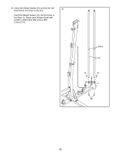
10. Attach each Weight Guide with an M10 x 63mm Bolt (89) and an M10 Locknut (74). Holes 31 74 74 1 89 11 Orient the Weight Guides (31) so that the indicated holes are closer to the floor. 10 Insert the Weight Guides (31) into the holes in the Base (1).
10. Attach each Weight Guide with an M10 x 63mm Bolt (89) and an M10 Locknut (74). Holes 31 74 74 1 89 11 Orient the Weight Guides (31) so that the indicated holes are closer to the floor. 10 Insert the Weight Guides (31) into the holes in the Base (1).
English Manual
Page 12
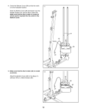
Make sure that the Burn Cable is routed as shown. 12 Attach the Bottom Cover (28) to the Base (1) with two ST4.2 x 19mm Screws (90). 90 1 28 45 12 Make sure that the Burn Cable (45) is routed as shown and is in the Bottom Cover. 45 Notch 31 28 12. 11. Orient the Bottom Cover (28) so that the notch is inserted into the notch in the indicated location. 11 Slide the Bottom Cover (28) downward over the Weight Guides (31) and the Burn Cable (45).
Make sure that the Burn Cable is routed as shown. 12 Attach the Bottom Cover (28) to the Base (1) with two ST4.2 x 19mm Screws (90). 90 1 28 45 12 Make sure that the Burn Cable (45) is routed as shown and is in the Bottom Cover. 45 Notch 31 28 12. 11. Orient the Bottom Cover (28) so that the notch is inserted into the notch in the indicated location. 11 Slide the Bottom Cover (28) downward over the Weight Guides (31) and the Burn Cable (45).
English Manual
Page 13
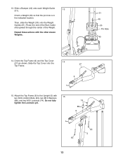
Slide a Bumper (40) onto each Weight Guide (31). 13 Orient a Weight (30) so that the pin hole is in the indicated location. Orient the Top Frame (6) and the Top Cover (27) as shown. Route the end of the Burn Cable (45) upward through the center of the Weight. Repeat these actions with 15 two M10 x 93mm Bolts (63), two M10 Washers (88), and two M10 Locknuts (74). Do not fully tighten the Locknuts yet. 74 88 6 63 13 63 5 Then, slide the Weight (30) onto the Weight Guides (31). Slide the Top Cover onto the 14 27 Top Frame. 6 15. Attach the Top Frame (6) to the Upright ...
Slide a Bumper (40) onto each Weight Guide (31). 13 Orient a Weight (30) so that the pin hole is in the indicated location. Orient the Top Frame (6) and the Top Cover (27) as shown. Route the end of the Burn Cable (45) upward through the center of the Weight. Repeat these actions with 15 two M10 x 93mm Bolts (63), two M10 Washers (88), and two M10 Locknuts (74). Do not fully tighten the Locknuts yet. 74 88 6 63 13 63 5 Then, slide the Weight (30) onto the Weight Guides (31). Slide the Top Cover onto the 14 27 Top Frame. 6 15. Attach the Top Frame (6) to the Upright ...
English Manual
Page 14
See step 15. Note: For clarity, the Top Cover (27) is not shown. 17 Route the Burn Cable (45) over two Burn Pulleys (68). Tighten the M10 Locknuts (74). 17. Attach each Burn Pulley (68) to the Weight 16 Guides (31) with an M10 x 40mm Bolt (97) and an M10 Locknut (74). 74 86 86 6 65 65 31 74 68 68 45 6 97 14 16. Attach the Top Frame (6) to the right side of the Top Frame (6) with two M10 x 43mm Bolts (65), two M10 Curved Washers (86), and two M10 Locknuts (74).
See step 15. Note: For clarity, the Top Cover (27) is not shown. 17 Route the Burn Cable (45) over two Burn Pulleys (68). Tighten the M10 Locknuts (74). 17. Attach each Burn Pulley (68) to the Weight 16 Guides (31) with an M10 x 40mm Bolt (97) and an M10 Locknut (74). 74 86 86 6 65 65 31 74 68 68 45 6 97 14 16. Attach the Top Frame (6) to the right side of the Top Frame (6) with two M10 x 43mm Bolts (65), two M10 Curved Washers (86), and two M10 Locknuts (74).

English Manual
Page 15
Attach the Left and Right Press Arms (17, 18) to attach the Right Butterfly Arm (16) and the Right Butterfly Pulley Bracket (21). 19 16 21 74 52 20 7 Grease 15 11 15 the Butterfly Arm must pivot easily. Repeat this step to the Base (1) with the M10 x 130mm Bolt (11) and an M10 Locknut (74). 18. Insert the Press Arm Spacer (42) between the Left and Right Press Arms (17, 18) as shown. Do not overtighten the Locknut; Identify the Left and Right Press Arms (17, 18) and orient them as shown. the Press Arms must pivot easily. Identify the Butterfly Frame (7), the Left ...
Attach the Left and Right Press Arms (17, 18) to attach the Right Butterfly Arm (16) and the Right Butterfly Pulley Bracket (21). 19 16 21 74 52 20 7 Grease 15 11 15 the Butterfly Arm must pivot easily. Repeat this step to the Base (1) with the M10 x 130mm Bolt (11) and an M10 Locknut (74). 18. Insert the Press Arm Spacer (42) between the Left and Right Press Arms (17, 18) as shown. Do not overtighten the Locknut; Identify the Left and Right Press Arms (17, 18) and orient them as shown. the Press Arms must pivot easily. Identify the Butterfly Frame (7), the Left ...

English Manual
Page 16
Do not fully tighten the Locknuts yet. Insert a Ball Detention Assembly (96) into the Left and Right Butterfly Arms (15, 16). 63 6 88 16 96 96 15 7 74 21. 20. Finish attaching the Butterfly Frame (7) to the Top Frame (6) with two M10 x 117mm Bolts (64), four M10 Washers (88), and two M10 Locknuts (74). See step 20. Attach the Butterfly Frame (7) to the Top Frame (6) with two M10 x 93mm Bolts (63), two M10 20 Washers (88), and two M10 Locknuts (74). Tighten the M10 Locknuts (74). 21 74 6 88 88 64 7 16
Do not fully tighten the Locknuts yet. Insert a Ball Detention Assembly (96) into the Left and Right Butterfly Arms (15, 16). 63 6 88 16 96 96 15 7 74 21. 20. Finish attaching the Butterfly Frame (7) to the Top Frame (6) with two M10 x 117mm Bolts (64), four M10 Washers (88), and two M10 Locknuts (74). See step 20. Attach the Butterfly Frame (7) to the Top Frame (6) with two M10 x 93mm Bolts (63), two M10 20 Washers (88), and two M10 Locknuts (74). Tighten the M10 Locknuts (74). 21 74 6 88 88 64 7 16

English Manual
Page 17
Identify the Low Cable (43). See drawing 24a. Attach a Pulley (69) inside the Leg (10) with an M10 x 65mm Bolt (75), two M10 Washers (88), two 12.7mm Spacers (73), and an M10 Locknut (74). 24. Attach a Pulley (69) to the bracket on the Leg Lever 22 (13). Route the Low Cable (43) over the Low Cable (43) with an M10 x 63mm Bolt (89), two 12.7mm Spacers (73), and an M10 Locknut (74). 13 74 73 69 43 73 89 23. Route the Low Cable through the bracket on the Base (1) over a Pulley (69) and through the Leg (10). 23 Attach the Pulley (69) inside the Leg Lever (13) over the Low ...
Identify the Low Cable (43). See drawing 24a. Attach a Pulley (69) inside the Leg (10) with an M10 x 65mm Bolt (75), two M10 Washers (88), two 12.7mm Spacers (73), and an M10 Locknut (74). 24. Attach a Pulley (69) to the bracket on the Leg Lever 22 (13). Route the Low Cable (43) over the Low Cable (43) with an M10 x 63mm Bolt (89), two 12.7mm Spacers (73), and an M10 Locknut (74). 13 74 73 69 43 73 89 23. Route the Low Cable through the bracket on the Base (1) over a Pulley (69) and through the Leg (10). 23 Attach the Pulley (69) inside the Leg Lever (13) over the Low ...
English Manual
Page 18
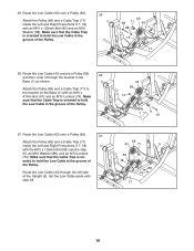
Route the Low Cable (43) over a Pulley (69). 25 Attach the Pulley (69) and a Cable Trap (71) inside the Left and Right Press Arms (17, 18) with the M10 x 125mm Bolt (83) used in the 26 Base (1) as shown. Make sure that the Cable Trap is oriented to hold the Low Cable in the groove of the Pulley. 43 69 74 1 71 91 27. 25. Route the Low Cable (43) over a Pulley (69). 27 Attach the Pulley (69) and a Cable Trap (71) inside the Left and Right Press Arms (17, 18) with an M10 x 47mm Bolt (91) and an M10 Locknut (74). Make sure that the Cable Trap is oriented to the ...
Route the Low Cable (43) over a Pulley (69). 25 Attach the Pulley (69) and a Cable Trap (71) inside the Left and Right Press Arms (17, 18) with the M10 x 125mm Bolt (83) used in the 26 Base (1) as shown. Make sure that the Cable Trap is oriented to hold the Low Cable in the groove of the Pulley. 43 69 74 1 71 91 27. 25. Route the Low Cable (43) over a Pulley (69). 27 Attach the Pulley (69) and a Cable Trap (71) inside the Left and Right Press Arms (17, 18) with an M10 x 47mm Bolt (91) and an M10 Locknut (74). Make sure that the Cable Trap is oriented to the ...
English Manual
Page 19
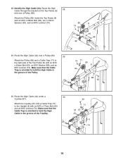
Attach the Pulley (69) inside the Top Frame (6) with an M10 x 57mm Bolt (93) and an M10 Locknut (74). Attach the V-pulley (67) and a Cable Trap (71) to hold the High Cable in the groove of the V-pulley. 93 71 44 67 5 74 19 Route the High Cable (44) under a 30 V-pulley (67). Make sure that the Cable Trap is oriented to the right side of the Pulley. 74 71 69 6 44 88 63 30. 28. Route the High Cable through the bracket on the Top Frame (6) 28 and over a Pulley (69). 29 Attach the Pulley (69) and a Cable Trap (71) to hold the High Cable in the groove of the Top ...
Attach the Pulley (69) inside the Top Frame (6) with an M10 x 57mm Bolt (93) and an M10 Locknut (74). Attach the V-pulley (67) and a Cable Trap (71) to hold the High Cable in the groove of the V-pulley. 93 71 44 67 5 74 19 Route the High Cable (44) under a 30 V-pulley (67). Make sure that the Cable Trap is oriented to the right side of the Pulley. 74 71 69 6 44 88 63 30. 28. Route the High Cable through the bracket on the Top Frame (6) 28 and over a Pulley (69). 29 Attach the Pulley (69) and a Cable Trap (71) to hold the High Cable in the groove of the Top ...
English Manual
Page 20
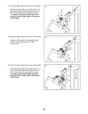
Route the High Cable (44) around a Pulley (69). 33 Attach the Pulley (69) and a Cable Trap (71) to the Upright (5) with an M10 x 43mm Bolt (65) and an M10 Locknut (74). 33. Route the High Cable (44) around a Pulley (69). 31 Attach the Pulley (69) and a Cable Trap (71) to hold the High Cable in the groove of the Pulley. 32. Route the High Cable (44) around a Pulley (69). 32 Attach the Pulley (69) to the Left Butterfly Pulley Bracket (20) with an M10 x 47mm Bolt (91) and an M10 Locknut (74). Make sure that the Cable Trap is oriented to the Right Butterfly Pulley Bracket (...
Route the High Cable (44) around a Pulley (69). 33 Attach the Pulley (69) and a Cable Trap (71) to the Upright (5) with an M10 x 43mm Bolt (65) and an M10 Locknut (74). 33. Route the High Cable (44) around a Pulley (69). 31 Attach the Pulley (69) and a Cable Trap (71) to hold the High Cable in the groove of the Pulley. 32. Route the High Cable (44) around a Pulley (69). 32 Attach the Pulley (69) to the Left Butterfly Pulley Bracket (20) with an M10 x 47mm Bolt (91) and an M10 Locknut (74). Make sure that the Cable Trap is oriented to the Right Butterfly Pulley Bracket (...
English Manual
Page 21
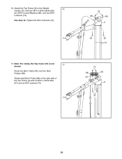
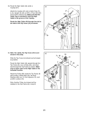
34. Make sure that the Cable Trap is not shown in the groove of the Top Cover (27) as shown. Route the High Cable (44) through the Top Frame as shown. 27 Slot 74 71 67 93 44 5 35. Note: For clarity, the Top Cover (27) is oriented to hold the High Cable in this step. 35 Slide the Top Cover (not shown) as far forward as possible. Attach the Pulley (69) inside the Top Frame (6) with an M10 x 57mm Bolt (93) and an M10 Locknut (74). Route the High Cable (44) upward through the Top Frame (6), over a Pulley (69), and downward through the slot in the side of the V-pulley...
34. Make sure that the Cable Trap is not shown in the groove of the Top Cover (27) as shown. Route the High Cable (44) through the Top Frame as shown. 27 Slot 74 71 67 93 44 5 35. Note: For clarity, the Top Cover (27) is oriented to hold the High Cable in this step. 35 Slide the Top Cover (not shown) as far forward as possible. Attach the Pulley (69) inside the Top Frame (6) with an M10 x 57mm Bolt (93) and an M10 Locknut (74). Route the High Cable (44) upward through the Top Frame (6), over a Pulley (69), and downward through the slot in the side of the V-pulley...