
English Manual
Page 1
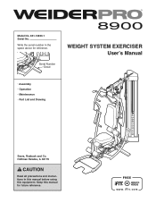
Keep this equipment. Model No. 831.14923.1 Serial No. Serial Number Decal WEIGHT SYSTEM EXERCISER Userʼs Manual • Assembly • Operation • Maintenance • Part List and Drawing Sears, Roebuck and Co. Hoffman Estates, IL 60179 CAUTION Read all precautions and instructions in the space above for future reference. Write the serial number in this manual before using this manual for reference.
Keep this equipment. Model No. 831.14923.1 Serial No. Serial Number Decal WEIGHT SYSTEM EXERCISER Userʼs Manual • Assembly • Operation • Maintenance • Part List and Drawing Sears, Roebuck and Co. Hoffman Estates, IL 60179 CAUTION Read all precautions and instructions in the space above for future reference. Write the serial number in this manual before using this manual for reference.

English Manual
Page 2
Note: The decal(s) may not be shown at actual size. 2 TABLE OF CONTENTS WARNING DECAL PLACEMENT 2 IMPORTANT PRECAUTIONS 3 BEFORE YOU BEGIN 4 PART IDENTIFICATION CHART 5 ASSEMBLY 7 ADJUSTMENT 34 WEIGHT RESISTANCE CHART 37 CABLE DIAGRAM 38 MAINTENANCE 39 EXERCISE GUIDELINES 40 PART LIST 43 EXPLODED DRAWING 45 ORDERING REPLACEMENT PARTS Back Cover ...
Note: The decal(s) may not be shown at actual size. 2 TABLE OF CONTENTS WARNING DECAL PLACEMENT 2 IMPORTANT PRECAUTIONS 3 BEFORE YOU BEGIN 4 PART IDENTIFICATION CHART 5 ASSEMBLY 7 ADJUSTMENT 34 WEIGHT RESISTANCE CHART 37 CABLE DIAGRAM 38 MAINTENANCE 39 EXERCISE GUIDELINES 40 PART LIST 43 EXPLODED DRAWING 45 ORDERING REPLACEMENT PARTS Back Cover ...
English Manual
Page 4
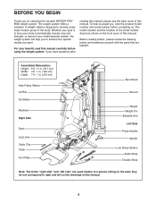
... side" are used relative to develop every major muscle group of this manual carefully before contacting us assist you for selecting the versatile WEIDER PRO™ 8900 weight system. For your cardiovascular system, the weight system will help us . Before reading further, please review the drawing below and... Low Pulley Station Ankle Strap Double Strap Note: The terms "right side" and "left on the front cover of the serial number decal are labeled. Assembled Dimensions: Height: 6 ft. 11 in. (211 cm) Width: 4 ft. 1 in. (124 cm) Depth: 7 ft. 1 in this manual. Whether your ...
... side" are used relative to develop every major muscle group of this manual carefully before contacting us assist you for selecting the versatile WEIDER PRO™ 8900 weight system. For your cardiovascular system, the weight system will help us . Before reading further, please review the drawing below and... Low Pulley Station Ankle Strap Double Strap Note: The terms "right side" and "left on the front cover of the serial number decal are labeled. Assembled Dimensions: Height: 6 ft. 11 in. (211 cm) Width: 4 ft. 1 in. (124 cm) Depth: 7 ft. 1 in this manual. Whether your ...

English Manual
Page 5
... key number of the part, from the PART LIST near the end of this manual. To avoid damaging parts, do not use power tools for assembly. PART IDENTIFICATION CHART Refer to the drawings below to see if it has been preassembled. IMPORTANT: If you cannot find a part in the hardware kit...
... key number of the part, from the PART LIST near the end of this manual. To avoid damaging parts, do not use power tools for assembly. PART IDENTIFICATION CHART Refer to the drawings below to see if it has been preassembled. IMPORTANT: If you cannot find a part in the hardware kit...
English Manual
Page 7
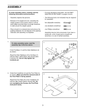
... or a set of ratchet wrenches. 1. Do not overtighten the Screws; Make sure that the textured side of the packing materials until assembly is enough clearance to walk around the weight system. • Place all parts in the box above. Do not dispose of 2 ...Screws (82). Orient the U-stabilizer (3) and the Foot Plate (4) as shown. the Foot Plate must pivot easily. 4 82 7 To make assembly easier, carefully read the assembly tips in a cleared area and remove the packing materials. Attach the Side Stabilizers (2) to the U-stabilizer (3) with two M10 x 95mm Bolts...
... or a set of ratchet wrenches. 1. Do not overtighten the Screws; Make sure that the textured side of the packing materials until assembly is enough clearance to walk around the weight system. • Place all parts in the box above. Do not dispose of 2 ...Screws (82). Orient the U-stabilizer (3) and the Foot Plate (4) as shown. the Foot Plate must pivot easily. 4 82 7 To make assembly easier, carefully read the assembly tips in a cleared area and remove the packing materials. Attach the Side Stabilizers (2) to the U-stabilizer (3) with two M10 x 95mm Bolts...
English Manual
Page 10
Attach a Burn Pulley (68) over the Burn Cable (45) inside the bracket on the Base (1) as you assemble them. 8 Identify the Burn Cable (45). Identify the four Burn Pulleys (68), the three V-pulleys (not shown), and the twenty Pulleys (not shown). Apply some ...
Attach a Burn Pulley (68) over the Burn Cable (45) inside the bracket on the Base (1) as you assemble them. 8 Identify the Burn Cable (45). Identify the four Burn Pulleys (68), the three V-pulleys (not shown), and the twenty Pulleys (not shown). Apply some ...

English Manual
Page 16
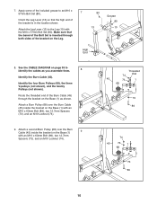
Attach the Butterfly Frame (7) to the Top Frame (6) with two M10 x 93mm Bolts (63), two M10 20 Washers (88), and two M10 Locknuts (74). Tighten the M10 Locknuts (74). 21 74 6 88 88 64 7 16 20. Finish attaching the Butterfly Frame (7) to the Top Frame (6) with two M10 x 117mm Bolts (64), four M10 Washers (88), and two M10 Locknuts (74). See step 20. Insert a Ball Detention Assembly (96) into the Left and Right Butterfly Arms (15, 16). 63 6 88 16 96 96 15 7 74 21. Do not fully tighten the Locknuts yet.
Attach the Butterfly Frame (7) to the Top Frame (6) with two M10 x 93mm Bolts (63), two M10 20 Washers (88), and two M10 Locknuts (74). Tighten the M10 Locknuts (74). 21 74 6 88 88 64 7 16 20. Finish attaching the Butterfly Frame (7) to the Top Frame (6) with two M10 x 117mm Bolts (64), four M10 Washers (88), and two M10 Locknuts (74). See step 20. Insert a Ball Detention Assembly (96) into the Left and Right Butterfly Arms (15, 16). 63 6 88 16 96 96 15 7 74 21. Do not fully tighten the Locknuts yet.
English Manual
Page 38
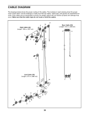
The numbers in . (686 cm) 10 11 4 5 7 8 2 1 6 3 38 2 1 If the cables are assembled correctly. Make sure that the cables, cable traps, and guards are not assembled correctly, the weight system will not function properly and damage may occur. Use the drawings to make sure that the cable traps do not touch ...
The numbers in . (686 cm) 10 11 4 5 7 8 2 1 6 3 38 2 1 If the cables are assembled correctly. Make sure that the cables, cable traps, and guards are not assembled correctly, the weight system will not function properly and damage may occur. Use the drawings to make sure that the cable traps do not touch ...
English Manual
Page 44
...2 96 2 97 2 98 1 99 1 100 1 101 2 102 1 M10 x 47mm Bolt Leg Lever Bumper M10 x 57mm Bolt 6.35mm Spacer 14.8mm Spacer Ball Detention Assembly M10 x 40mm Bolt M10 x 45mm Bolt M10 Jam Nut M10 x 97mm Bolt Lower Butterfly Bushing Top Frame Cap 103 2 104 2 105 2 106 1 107 4 108 4 109... Grip Lat Bar Cap Plastic Bushing Handle M4 x 12mm Bolt M4 Locknut Containment Bracket Left Side Shroud Userʼs Manual Exercise Guide Grease Packet Assembly Tool Note: Specifications are not illustrated. 44 If a part is missing, please call 1-877-992-5999. *These parts are subject to change...
...2 96 2 97 2 98 1 99 1 100 1 101 2 102 1 M10 x 47mm Bolt Leg Lever Bumper M10 x 57mm Bolt 6.35mm Spacer 14.8mm Spacer Ball Detention Assembly M10 x 40mm Bolt M10 x 45mm Bolt M10 Jam Nut M10 x 97mm Bolt Lower Butterfly Bushing Top Frame Cap 103 2 104 2 105 2 106 1 107 4 108 4 109... Grip Lat Bar Cap Plastic Bushing Handle M4 x 12mm Bolt M4 Locknut Containment Bracket Left Side Shroud Userʼs Manual Exercise Guide Grease Packet Assembly Tool Note: Specifications are not illustrated. 44 If a part is missing, please call 1-877-992-5999. *These parts are subject to change...


