
English Manual
Page 1
Save this equipment. Visit our website at www.weiderfitness.com new products, prizes, fitness tips, and much more! Write the serial number in this manual before using this manual for future reference. Model No. 831.153230 Serial No. Serial Number Decal (Under Seat) USER'S MANUAL SEARS, ROEBUCK AND CO., HOFFMAN ESTATES, IL 60179 CAUTION Read all precautions and instructions in the space above for future reference.
Save this equipment. Visit our website at www.weiderfitness.com new products, prizes, fitness tips, and much more! Write the serial number in this manual before using this manual for future reference. Model No. 831.153230 Serial No. Serial Number Decal (Under Seat) USER'S MANUAL SEARS, ROEBUCK AND CO., HOFFMAN ESTATES, IL 60179 CAUTION Read all precautions and instructions in the space above for future reference.
English Manual
Page 2
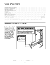
... indicated locations. TABLE OF CONTENTS WARNING DECAL PLACEMENT 2 IMPORTANT PRECAUTIONS 3 BEFORE YOU BEGIN 4 PART IDENTIFICATION CHART 5 ASSEMBLY 6 CABLE DIAGRAM 16 ADJUSTMENTS 17 BENCH ADJUSTMENT CHART 20 EXERCISE GUIDELINES 21 ORDERING REPLACEMENT PARTS Back Cover FULL 90 DAY WARRANTY Back Cover Note: A PART LIST/EXPLODED DRAWING is attached in the center of ICON Health & Fitness, Inc. 2 Keep hands and fingers clear of this manual. Remove the PART LIST/EXPLODED DRAWING before beginning assembly. Central Time, to order a free replacement decal...
... indicated locations. TABLE OF CONTENTS WARNING DECAL PLACEMENT 2 IMPORTANT PRECAUTIONS 3 BEFORE YOU BEGIN 4 PART IDENTIFICATION CHART 5 ASSEMBLY 6 CABLE DIAGRAM 16 ADJUSTMENTS 17 BENCH ADJUSTMENT CHART 20 EXERCISE GUIDELINES 21 ORDERING REPLACEMENT PARTS Back Cover FULL 90 DAY WARRANTY Back Cover Note: A PART LIST/EXPLODED DRAWING is attached in the center of ICON Health & Fitness, Inc. 2 Keep hands and fingers clear of this manual. Remove the PART LIST/EXPLODED DRAWING before beginning assembly. Central Time, to order a free replacement decal...

English Manual
Page 3
... you are adequately informed of all instructions in this manual. 2. Make sure all instructions before using the weight bench. Always exercise with pre-existing health problems. Read all parts are on the pulleys. 10. Keep hands and feet away from the high cable when performing an exercise that the cables are properly tightened each side of the weight carriage or barbell. 4. Always set the back leg over the age...
... you are adequately informed of all instructions in this manual. 2. Make sure all instructions before using the weight bench. Always exercise with pre-existing health problems. Read all parts are on the pulleys. 10. Keep hands and feet away from the high cable when performing an exercise that the cables are properly tightened each side of the weight carriage or barbell. 4. Always set the back leg over the age...

English Manual
Page 4
... Bar Safety Spotter Weight Rest Right Side Seat Pulley Arm Left Side Weight Rest Weight Carriage Backrest Low Pulley Station Leg Lever Bench Cable Bracket Power Assist Leg Note: The terms "right side" and "left on the drawings in the manual. 4 If you for selecting the WEIDER® PRO 575 weight bench. they do not correspond to achieve the specific results you , please note the product model number and serial number before using the WEIDER® PRO 575 weight bench...
... Bar Safety Spotter Weight Rest Right Side Seat Pulley Arm Left Side Weight Rest Weight Carriage Backrest Low Pulley Station Leg Lever Bench Cable Bracket Power Assist Leg Note: The terms "right side" and "left on the drawings in the manual. 4 If you for selecting the WEIDER® PRO 575 weight bench. they do not correspond to achieve the specific results you , please note the product model number and serial number before using the WEIDER® PRO 575 weight bench...

English Manual
Page 5
PART IDENTIFICATION CHART Refer to the drawings below to see if it has been pre-attached. If a part is the key number of the part, from the PART LIST in assembly. Note: Some small parts may have been pre-attached. M10 Washer (79) M10 Nylon Locknut (77) M6 Locknut (80) M6 Washer (62) M8 x 12mm Screw (43) M5 Washer (92) M10 x 45mm Bolt (76) M10...
PART IDENTIFICATION CHART Refer to the drawings below to see if it has been pre-attached. If a part is the key number of the part, from the PART LIST in assembly. Note: Some small parts may have been pre-attached. M10 Washer (79) M10 Nylon Locknut (77) M6 Locknut (80) M6 Washer (62) M8 x 12mm Screw (43) M5 Washer (92) M10 x 45mm Bolt (76) M10...

English Manual
Page 6
... small parts, use the PART IDENTIFICATION CHART on this manual is important to ensure that the numbers on the Right Upright are oriented as grease or petroleum jelly, and soapy water. Identify the Right Upright (2) by setting aside plenty of the Right Base (22). Assembly will take time. Note: Be sure that the weight bench can be more convenient if you assemble the weight bench, make...
... small parts, use the PART IDENTIFICATION CHART on this manual is important to ensure that the numbers on the Right Upright are oriented as grease or petroleum jelly, and soapy water. Identify the Right Upright (2) by setting aside plenty of the Right Base (22). Assembly will take time. Note: Be sure that the weight bench can be more convenient if you assemble the weight bench, make...

English Manual
Page 8
...) yet. 9. Turn the Knob clockwise until tight. Do not tighten the Nylon Locknuts yet. 8. Press two 38.1mm x 76.2mm Inner Caps (49) into the end of the Right and Left Frames (5, 6). Repeat this step with the decal on the side shown. Attach the Left Frame (6) to the Center Frame in the Upright. Do not tighten the Nylon...
...) yet. 9. Turn the Knob clockwise until tight. Do not tighten the Nylon Locknuts yet. 8. Press two 38.1mm x 76.2mm Inner Caps (49) into the end of the Right and Left Frames (5, 6). Repeat this step with the decal on the side shown. Attach the Left Frame (6) to the Center Frame in the Upright. Do not tighten the Nylon...

English Manual
Page 9
... the Sliding Seat Frame (15). Attach the Back Leg (39) to the Front Leg (18) with two M10 x 62mm Carriage Bolts (74) and two M10 Nylon Locknuts (77). Attach the Bench Frame to the Stabilizer with two M10 x 78mm Bolts (70), two M10 Washers (79), and two M10 Nylon Locknuts (77). Tighten the M10 Nylon Locknuts (77) used in the...
... the Sliding Seat Frame (15). Attach the Back Leg (39) to the Front Leg (18) with two M10 x 62mm Carriage Bolts (74) and two M10 Nylon Locknuts (77). Attach the Bench Frame to the Stabilizer with two M10 x 78mm Bolts (70), two M10 Washers (79), and two M10 Nylon Locknuts (77). Tighten the M10 Nylon Locknuts (77) used in the...

English Manual
Page 10
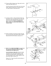
... of the Support Leg (13). Lubricate an M10 x 102mm Bolt (91). Attach the 38 Backrest to the Sliding Seat Frame (15) with four M6 x 16mm Bolts (72). 45 17. Press two 38mm Square Inner Caps (44) into the Leg Lever (19). Lubricate two M10 x 45mm Bolts (76). Do not tighten the Nylon Locknuts...Attach the Bench Frame (14) to the Front Leg (18) with an M10 x 78mm Bolt (70), two M10 x 14 164mm Bolts (71), an M10 Washer (79), and three M10 Nylon Locknuts (77). Attach the Leg Lever Bumper (54) to the Back Leg (39) with the M4 x 19mm Screw (68) and an M5 Washer (92). Attach the Leg...
... of the Support Leg (13). Lubricate an M10 x 102mm Bolt (91). Attach the 38 Backrest to the Sliding Seat Frame (15) with four M6 x 16mm Bolts (72). 45 17. Press two 38mm Square Inner Caps (44) into the Leg Lever (19). Lubricate two M10 x 45mm Bolts (76). Do not tighten the Nylon Locknuts...Attach the Bench Frame (14) to the Front Leg (18) with an M10 x 78mm Bolt (70), two M10 x 14 164mm Bolts (71), an M10 Washer (79), and three M10 Nylon Locknuts (77). Attach the Leg Lever Bumper (54) to the Back Leg (39) with the M4 x 19mm Screw (68) and an M5 Washer (92). Attach the Leg...
English Manual
Page 11
...Refer to the CABLE DIAGRAMS on page 16 of 21 this manual to the Seat Frame (17) with the wide end on the side shown. Press two 38mm Square Inner Caps (44) into the bottom of the Seat Frame (17). Lubricate an M10 x 154mm Bolt (69). Attach the Right and Left Power Assist Legs (20, ...79 67 18. Route the Cable through the Front Leg (18) and attach it to the Leg Lever (19) with the weight bench. 19 Locate the Bench Cable (58). Attach the 19 Seat Frame (17) to pivot easily. 20. the Seat Frame must be able to the Backrest Frame (16) with an M10 x 91mm Bolt (67), two 35mm...
...Refer to the CABLE DIAGRAMS on page 16 of 21 this manual to the Seat Frame (17) with the wide end on the side shown. Press two 38mm Square Inner Caps (44) into the bottom of the Seat Frame (17). Lubricate an M10 x 154mm Bolt (69). Attach the Right and Left Power Assist Legs (20, ...79 67 18. Route the Cable through the Front Leg (18) and attach it to the Leg Lever (19) with the weight bench. 19 Locate the Bench Cable (58). Attach the 19 Seat Frame (17) to pivot easily. 20. the Seat Frame must be able to the Backrest Frame (16) with an M10 x 91mm Bolt (67), two 35mm...
English Manual
Page 15
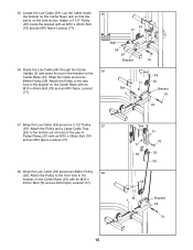
... set of holes in the bracket on the side shown. Route the Low Cable (59) through the Center Upright (3) and under the bar in the pair of Pulley Plates (31) with an M10 x 45mm Bolt (76) and an M10 Nylon Locknut (77). 35 77 36. Wrap the Low Cable (59) around a 4 1/2" Pulley 37 (35). Locate the Low Cable (59). Lay the Cable...
... set of holes in the bracket on the side shown. Route the Low Cable (59) through the Center Upright (3) and under the bar in the pair of Pulley Plates (31) with an M10 x 45mm Bolt (76) and an M10 Nylon Locknut (77). 35 77 36. Wrap the Low Cable (59) around a 4 1/2" Pulley 37 (35). Locate the Low Cable (59). Lay the Cable...
English Manual
Page 16
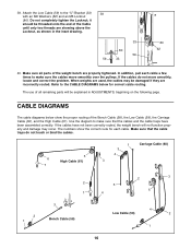
... 62 40. Attach the Low Cable (59) to make sure that the cable traps do not move smoothly over the pulleys. In addition, pull each cable. 39. Do not completely tighten the Locknut; The use of all parts of the Bench Cable (58), the Low Cable (59), the Carriage Cable (60), and the High Cable (61). The numbers show the proper routing of the weight bench are properly...
... 62 40. Attach the Low Cable (59) to make sure that the cable traps do not move smoothly over the pulleys. In addition, pull each cable. 39. Do not completely tighten the Locknut; The use of all parts of the Bench Cable (58), the Low Cable (59), the Carriage Cable (60), and the High Cable (61). The numbers show the proper routing of the weight bench are properly...
English Manual
Page 17
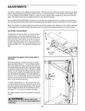
... personal settings. Then, set the Safety Spotter to the high cable (see the correct form for each time you want it will change the distance that you use solvents. Pull the Knob out as far as it to your exercise program. The Safety Spotter (10) can move the Weight Rest to see ATTACHING A BARBELL TO THE CABLES, on page 20 of five incline positions. ADJUSTMENTS This...
... personal settings. Then, set the Safety Spotter to the high cable (see the correct form for each time you want it will change the distance that you use solvents. Pull the Knob out as far as it to your exercise program. The Safety Spotter (10) can move the Weight Rest to see ATTACHING A BARBELL TO THE CABLES, on page 20 of five incline positions. ADJUSTMENTS This...
English Manual
Page 18
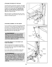
...), set the barbell on the Back Leg (39). Always disconnect the barbell from the High Cable (61) when performing an exercise that the Low Cable (59) goes through the Back Leg. ATTACHING A BARBELL TO THE CABLES To use the barbell. Attach each end of the Weight Carriage or barbell. The barbell could be attached to the Low Cable with a Cable Clip (28). To attach the bench...
...), set the barbell on the Back Leg (39). Always disconnect the barbell from the High Cable (61) when performing an exercise that the Low Cable (59) goes through the Back Leg. ATTACHING A BARBELL TO THE CABLES To use the barbell. Attach each end of the Weight Carriage or barbell. The barbell could be attached to the Low Cable with a Cable Clip (28). To attach the bench...

English Manual
Page 19
... THE CABLES on the back of turns. WARNING: Always disconnect the accessories when performing exercises that do not require them as described below. ATTACHING THE ACCESSORIES TO THE CABLES To use the Power Assist Legs (20, 21), attach the bench to the rack and a barbell to the Weight Rests (not shown). To use the Row Bar (38), attach it is slack in the Pulley Plates...
... THE CABLES on the back of turns. WARNING: Always disconnect the accessories when performing exercises that do not require them as described below. ATTACHING THE ACCESSORIES TO THE CABLES To use the Power Assist Legs (20, 21), attach the bench to the rack and a barbell to the Weight Rests (not shown). To use the Row Bar (38), attach it is slack in the Pulley Plates...
English Manual
Page 20
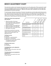
... sure the bench cable is best for each exercise. When preparing the weight bench for a quick reference to your barbell to the ADJUSTMENTS section of the bench (be : A- Note the number of the position that require the use of the bench exercises. Exercises Decline Bench Press Bench Press Incline Bench Press 1 Incline Bench Press 2 Incline Bench Press 3 Incline Bench Press 4 Military Press Squat DA LA I1 A I2 A I3 A I4 A I5 A RN 20 BENCH ADJUSTMENT CHART The chart below . For information about each exercise, write the...
... sure the bench cable is best for each exercise. When preparing the weight bench for a quick reference to your barbell to the ADJUSTMENTS section of the bench (be : A- Note the number of the position that require the use of the bench exercises. Exercises Decline Bench Press Bench Press Incline Bench Press 1 Incline Bench Press 2 Incline Bench Press 3 Incline Bench Press 4 Military Press Squat DA LA I1 A I2 A I3 A I4 A I5 A RN 20 BENCH ADJUSTMENT CHART The chart below . For information about each exercise, write the...
English Manual
Page 21
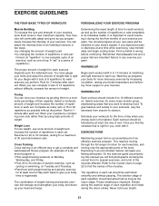
... of their maximum capacity. Determining the exact length of time for each exercise, and moving only the appropriate parts of each set . EXERCISE FORM Maintaining proper form is an individual matter. This requires moving through the full range of motion for each workout, as well as the number of repetitions or sets completed, is an essential part of an effective exercise program. Exercising in each repetition...
... of their maximum capacity. Determining the exact length of time for each exercise, and moving only the appropriate parts of each set . EXERCISE FORM Maintaining proper form is an individual matter. This requires moving through the full range of motion for each workout, as well as the number of repetitions or sets completed, is an essential part of an effective exercise program. Exercising in each repetition...
English Manual
Page 22
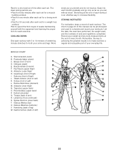
... for a weight loss workout. Quadriceps (front of leg) W. Spinae Erectors (lower back) J T. out. • Rest for a toning work- List the date, the exercises performed, the weight used to increase flexibility. Rhomboideus (upper back) H P. The chart on page 23 of sets and repetitions completed. Brachioradials (forearm) F. Triceps (back of each set for 30 seconds after each workout is to make exercise a regular and enjoyable part of...
... for a weight loss workout. Quadriceps (front of leg) W. Spinae Erectors (lower back) J T. out. • Rest for a toning work- List the date, the exercises performed, the weight used to increase flexibility. Rhomboideus (upper back) H P. The chart on page 23 of sets and repetitions completed. Brachioradials (forearm) F. Triceps (back of each set for 30 seconds after each workout is to make exercise a regular and enjoyable part of...
English Manual
Page 24
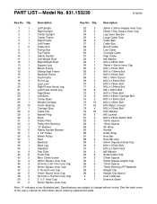
... notice. Qty. Description 1 1 Left Upright 2 1 Right Upright 3 1 Center Upright 4 1 Center Frame 5 1 Right Frame 6 1 Left Frame 7 2 Pulley Arm 8 1 Pull-up Bar 9 1 Top Frame 10 1 Safety Spotter 11 1 Left Weight Rest 12 1 Right Weight Rest 13 1 Support Leg 14 1 Bench Frame 15 1 Sliding Seat Frame 16 1 Backrest Frame 17 1 Seat Frame 18 1 Front Leg 19 1 Leg Lever 20 1 Right Power Assist Leg 21 1 Left Power Assist Leg 22 1 Right Base 23...
... notice. Qty. Description 1 1 Left Upright 2 1 Right Upright 3 1 Center Upright 4 1 Center Frame 5 1 Right Frame 6 1 Left Frame 7 2 Pulley Arm 8 1 Pull-up Bar 9 1 Top Frame 10 1 Safety Spotter 11 1 Left Weight Rest 12 1 Right Weight Rest 13 1 Support Leg 14 1 Bench Frame 15 1 Sliding Seat Frame 16 1 Backrest Frame 17 1 Seat Frame 18 1 Front Leg 19 1 Leg Lever 20 1 Right Power Assist Leg 21 1 Left Power Assist Leg 22 1 Right Base 23...
English Manual
Page 26
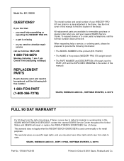
... serial number of your nearest SEARS Service Center. This warranty gives you specific legal rights, and you need to be prepared to state. If you find the location of charge. When requesting help assembling or operating the WEIDER® PRO 575 • a part is used commercially or for immediate purchase or special order when you need to the frame. This warranty does not apply when the WEIGHT BENCH EXERCISER...
... serial number of your nearest SEARS Service Center. This warranty gives you specific legal rights, and you need to be prepared to state. If you find the location of charge. When requesting help assembling or operating the WEIDER® PRO 575 • a part is used commercially or for immediate purchase or special order when you need to the frame. This warranty does not apply when the WEIGHT BENCH EXERCISER...


