
English Manual
Page 2
Remove the PART IDENTIFICATION CHART and the PART LIST/EXPLODED DRAWING before beginning assembly. 2 TABLE OF CONTENTS IMPORTANT PRECAUTIONS 3 BEFORE YOU BEGIN 4 ASSEMBLY 5 ADJUSTMENTS 21 WEIGHT RESISTANCE CHART 23 CABLE DIAGRAM 24 EXERCISE GUIDELINES 26 ORDERING REPLACEMENT PARTS Back Cover FULL 90 DAY WARRANTY Back Cover Note: A PART IDENTIFICATION CHART and a PART LIST/EXPLODED DRAWING are attached in the center of this manual.
Remove the PART IDENTIFICATION CHART and the PART LIST/EXPLODED DRAWING before beginning assembly. 2 TABLE OF CONTENTS IMPORTANT PRECAUTIONS 3 BEFORE YOU BEGIN 4 ASSEMBLY 5 ADJUSTMENTS 21 WEIGHT RESISTANCE CHART 23 CABLE DIAGRAM 24 EXERCISE GUIDELINES 26 ORDERING REPLACEMENT PARTS Back Cover FULL 90 DAY WARRANTY Back Cover Note: A PART IDENTIFICATION CHART and a PART LIST/EXPLODED DRAWING are attached in the center of this manual.
English Manual
Page 3
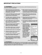
...before using . If you are exercising, stop immediately and begin cooling down. 5. Keep children under the age of the owner to ensure that the cables remain on a level surface. Never release the press arm, butterfly arms, leg lever, leg press base, lat bar, ab strap, or handle ... properly tightened each time the weight system is designed to tip. 3. Place the decal on the foot plate when performing an exercise that the cables are adequately informed of this manual. 11. Always stand on the weight system in a commercial, rental, or institutional setting. 13. Use the...
...before using . If you are exercising, stop immediately and begin cooling down. 5. Keep children under the age of the owner to ensure that the cables remain on a level surface. Never release the press arm, butterfly arms, leg lever, leg press base, lat bar, ab strap, or handle ... properly tightened each time the weight system is designed to tip. 3. Place the decal on the foot plate when performing an exercise that the cables are adequately informed of this manual. 11. Always stand on the weight system in a commercial, rental, or institutional setting. 13. Use the...
English Manual
Page 11
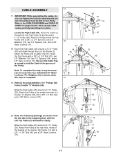
... with a 3/8" x 2 3/4" Bolt (81), two 3/8" Washers (75), two 1/2" Spacers (34), and a 3/8" Nylon Locknut (70). Refer to turn freely. Be sure the Cable Trap is completed. 19. Note: To complete this step is turned to loosen the four indicated 5/16" Nylon Locknuts (71). Wrap the High... Cable (45) around a 3 1/2" Pulley (38). Note: The following drawings are shown from a Double "U"-Bracket (56). Attach the Pulley inside of a Double "U"-Bracket (56) with a ...
... with a 3/8" x 2 3/4" Bolt (81), two 3/8" Washers (75), two 1/2" Spacers (34), and a 3/8" Nylon Locknut (70). Refer to turn freely. Be sure the Cable Trap is completed. 19. Note: To complete this step is turned to loosen the four indicated 5/16" Nylon Locknuts (71). Wrap the High... Cable (45) around a 3 1/2" Pulley (38). Note: The following drawings are shown from a Double "U"-Bracket (56). Attach the Pulley inside of a Double "U"-Bracket (56) with a ...
English Manual
Page 12
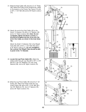
... shown in the "U"-Bracket. 22 79 69 70 14 45 38 66 45 71 35 65 82 45 65 23. Wrap the High Cable (45) around a 3 1/2" Pulley (38). it should be threaded only two turns onto the end of the bracket on the Center Top Frame (14) with a 3/8" x 2 3/4" Bolt (... 95 30 12 the Weight Tube should be able to the Weight Tube (82) with a 1/4" Washer (35) and a 1/4" Nylon Locknut (65). Wrap the Leg Press Cable (95) around a 3 1/2" Pulley 21 (38). 21. Do not overtighten the Locknut; Attach the Pulley inside the Leg Press Frame (30) with a 3/8" x 1 3/4" Bolt (66) and a 3/8" Nylon...
... shown in the "U"-Bracket. 22 79 69 70 14 45 38 66 45 71 35 65 82 45 65 23. Wrap the High Cable (45) around a 3 1/2" Pulley (38). it should be threaded only two turns onto the end of the bracket on the Center Top Frame (14) with a 3/8" x 2 3/4" Bolt (... 95 30 12 the Weight Tube should be able to the Weight Tube (82) with a 1/4" Washer (35) and a 1/4" Nylon Locknut (65). Wrap the Leg Press Cable (95) around a 3 1/2" Pulley 21 (38). 21. Do not overtighten the Locknut; Attach the Pulley inside the Leg Press Frame (30) with a 3/8" x 1 3/4" Bolt (66) and a 3/8" Nylon...
English Manual
Page 13
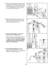
...). 25. Attach the Pulley inside the Upright with a 1/4" Washer (35) and a 1/4" Nylon Locknut (65). Note: Do not completely tighten the Locknut; Attach the 28 Cable to the "U"-Bracket (85) with a 3/8" x 2 3/4" Bolt (81), two 3/8" Washers (75), two 1/2" Spacers (34), and a 3/8" Nylon Locknut (70). 26. it... should be threaded only two turns onto the end of the Leg Press Cable (95) to the Pivot Bracket (48) on the Left Top Frame (3) with an 5/16" x 1" Shoulder Bolt (78) and a 5/16" Nylon Locknut (...
...). 25. Attach the Pulley inside the Upright with a 1/4" Washer (35) and a 1/4" Nylon Locknut (65). Note: Do not completely tighten the Locknut; Attach the 28 Cable to the "U"-Bracket (85) with a 3/8" x 2 3/4" Bolt (81), two 3/8" Washers (75), two 1/2" Spacers (34), and a 3/8" Nylon Locknut (70). 26. it... should be threaded only two turns onto the end of the Leg Press Cable (95) to the Pivot Bracket (48) on the Left Top Frame (3) with an 5/16" x 1" Shoulder Bolt (78) and a 5/16" Nylon Locknut (...
English Manual
Page 14
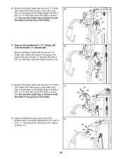
... the single hole side of the Pulley. 6 70 39 40 63 46 30. Attach the Pulley and a Long Cable Trap (40) to hold the Cable in the groove of the Pulley. 32. Be sure the Cable Trap is turned to the bracket on the Right Upright (6) with a 3/8" x 2" Bolt (62) and a 3/8" Nylon Locknut (70... the groove of the other Double "U"-Bracket (56) with a 3/8" x 2 1/2" Bolt (63) and a 3/8" Nylon Locknut (70). Attach the Pulley and a Long Cable Trap (40) to the Pivot Bracket (48) on the Right Upright (6) with a 32 5/16" x 1" Shoulder Bolt (78) and an 5/16" Nylon Locknut (71). 46 38 ...
... the single hole side of the Pulley. 6 70 39 40 63 46 30. Attach the Pulley and a Long Cable Trap (40) to hold the Cable in the groove of the Pulley. 32. Be sure the Cable Trap is turned to the bracket on the Right Upright (6) with a 3/8" x 2" Bolt (62) and a 3/8" Nylon Locknut (70... the groove of the other Double "U"-Bracket (56) with a 3/8" x 2 1/2" Bolt (63) and a 3/8" Nylon Locknut (70). Attach the Pulley and a Long Cable Trap (40) to the Pivot Bracket (48) on the Right Upright (6) with a 32 5/16" x 1" Shoulder Bolt (78) and an 5/16" Nylon Locknut (71). 46 38 ...
English Manual
Page 15
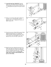
...(73) and attach it to the Leg Lever (4) with a 3/8" x 2" Bolt (62) and a 3/8" Nylon Locknut (70). Attach the Pulley and a Cable Trap (91) to hold the Cable in the indicated Double "U"-Bracket (56) with a 5/16" x 1" Shoulder Bolt (78) and a 5/16" Nylon Locknut (71). 33 4 71 73 ...34. Locate the Leg Lever Cable (96). Attach a 3 1/2" Pulley (38) inside the Upright with a 3/8" x 2 3/4" Bolt (81), two 3/8" Washers (75), two 1/2" Spacers (34), and a 3/8" Nylon ...
...(73) and attach it to the Leg Lever (4) with a 3/8" x 2" Bolt (62) and a 3/8" Nylon Locknut (70). Attach the Pulley and a Cable Trap (91) to hold the Cable in the indicated Double "U"-Bracket (56) with a 5/16" x 1" Shoulder Bolt (78) and a 5/16" Nylon Locknut (71). 33 4 71 73 ...34. Locate the Leg Lever Cable (96). Attach a 3 1/2" Pulley (38) inside the Upright with a 3/8" x 2 3/4" Bolt (81), two 3/8" Washers (75), two 1/2" Spacers (34), and a 3/8" Nylon ...
English Manual
Page 16
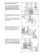
...70 34 75 81 7 47 36 40. Route the small ball 38 on the Leg Press Frame (30). 37. Route the Low Cable (47) through the cage on the Cable through the Left Leg 39 (36) and the Left Upright (7). Remove the preattached 3 1/2" Pulley (not 37 shown) from the ..."U"-Bracket (85). it should be threaded only two turns onto the end of the Leg Lever Cable (96) to the other "U"-Bracket (85) with a 3/8" x 2 3/4" Bolt (81), two 3/8" Washers (75), two 1/2" Spacers (34), and a 3/8" Nylon Locknut (70). 96 35...
...70 34 75 81 7 47 36 40. Route the small ball 38 on the Leg Press Frame (30). 37. Route the Low Cable (47) through the cage on the Cable through the Left Leg 39 (36) and the Left Upright (7). Remove the preattached 3 1/2" Pulley (not 37 shown) from the ..."U"-Bracket (85). it should be threaded only two turns onto the end of the Leg Lever Cable (96) to the other "U"-Bracket (85) with a 3/8" x 2 3/4" Bolt (81), two 3/8" Washers (75), two 1/2" Spacers (34), and a 3/8" Nylon Locknut (70). 96 35...
English Manual
Page 17
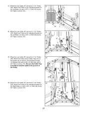
...) around a 3 1/2" Pulley 42 (38). Wrap the Low Cable (47) around a 3 1/2" Pulley 43 (38). Be sure the Cable Trap is turned to hold the Cable in the groove of holes in the indicated Double "U"-Bracket (56) with a 3/8" x 2" Bolt (62) and a 3/8" Nylon Locknut (70). 70 56 38 91 62 47 47 ...38 62 70 1 17 Attach the Pulley to the bottom set of the Pulley. 44. Attach the Pulley and a Cable Trap (91) to the indicated bracket on the Right Base (1) with a 3/8" x 2" Bolt (62) and a 3/8" Nylon Locknut (70). Attach the Pulley to the indicated bracket on...
...) around a 3 1/2" Pulley 42 (38). Wrap the Low Cable (47) around a 3 1/2" Pulley 43 (38). Be sure the Cable Trap is turned to hold the Cable in the groove of holes in the indicated Double "U"-Bracket (56) with a 3/8" x 2" Bolt (62) and a 3/8" Nylon Locknut (70). 70 56 38 91 62 47 47 ...38 62 70 1 17 Attach the Pulley to the bottom set of the Pulley. 44. Attach the Pulley and a Cable Trap (91) to the indicated bracket on the Right Base (1) with a 3/8" x 2" Bolt (62) and a 3/8" Nylon Locknut (70). Attach the Pulley to the indicated bracket on...
English Manual
Page 18
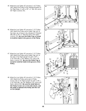
...85) with a 3/8" x Tabs 3 3/4" Bolt (84), two 3/8" Washers (75), and a 3/8" 75 Nylon Jamnut (50). Wrap the Low Cable (47) around a 3 1/2" Pulley 46 (38). Attach the Pulley and a Cable Trap (91) to the Right Upright (6) with a 3/8" x 2" Bolt (62) and a 3/8" Nylon Locknut (70). Attach the Pulley to ...a 3/8" x 3 3/4" Bolt (84), a 3/8" Washer (75), and a 3/8" Nylon Locknut (70). Wrap the Low Cable (47) around a 3 1/2" Pulley 48 (38). Attach the Pulley and a Cable Trap (91) to hold the Cable in the groove of holes in the groove of Pulley Small Covers (92) to the lower set of...
...85) with a 3/8" x Tabs 3 3/4" Bolt (84), two 3/8" Washers (75), and a 3/8" 75 Nylon Jamnut (50). Wrap the Low Cable (47) around a 3 1/2" Pulley 46 (38). Attach the Pulley and a Cable Trap (91) to the Right Upright (6) with a 3/8" x 2" Bolt (62) and a 3/8" Nylon Locknut (70). Attach the Pulley to ...a 3/8" x 3 3/4" Bolt (84), a 3/8" Washer (75), and a 3/8" Nylon Locknut (70). Wrap the Low Cable (47) around a 3 1/2" Pulley 48 (38). Attach the Pulley and a Cable Trap (91) to hold the Cable in the groove of holes in the groove of Pulley Small Covers (92) to the lower set of...
English Manual
Page 20
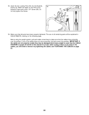
... find and correct the problem. IMPORTANT: If the cables are not properly routed, they may be explained in the cables, you will need to remove it by tightening the cables; see TIGHTENING THE CABLES on pages 24 and 25 of this manual for proper cable routing. Attach the tether on the following page. ...The use of the cables does not move smoothly over the pulleys....
... find and correct the problem. IMPORTANT: If the cables are not properly routed, they may be explained in the cables, you will need to remove it by tightening the cables; see TIGHTENING THE CABLES on pages 24 and 25 of this manual for proper cable routing. Attach the tether on the following page. ...The use of the cables does not move smoothly over the pulleys....
English Manual
Page 21
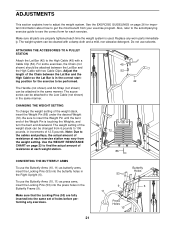
... Locking Pins (53) into the press holes in the same manner. Adjust the length of the Chain between the Lat Bar and the High Cable with two Cable Clips. To use the Butterfly Arms (10, 11) as butterfly arms, insert the Locking Pins (53) into the same set of resistance at each... in increments of the Weight Pin is used. ADJUSTMENTS This section explains how to see the correct form for each exercise. Note: Due to the cables and pulleys, the actual amount of the weight stack, insert the Weight Pin (86) under the desired Weight (72). Make sure that the Locking Pins...
... Locking Pins (53) into the press holes in the same manner. Adjust the length of the Chain between the Lat Bar and the High Cable with two Cable Clips. To use the Butterfly Arms (10, 11) as butterfly arms, insert the Locking Pins (53) into the same set of resistance at each... in increments of the Weight Pin is used. ADJUSTMENTS This section explains how to see the correct form for each exercise. Note: Due to the cables and pulleys, the actual amount of the weight stack, insert the Weight Pin (86) under the desired Weight (72). Make sure that the Locking Pins...
English Manual
Page 22
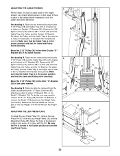
... Tube (88). Move the 3 1/2" Pulley (38) in the other Double "U"Bracket (56) in the same manner. Make sure that the Cable and Pulley move smoothly. To do this, you may need to the desired position and secure it is first used. ADJUSTING THE LEG PRESS PLATE...a "U"-Bracket (85). See drawing A. Slack can be removed by tightening the 1/4" Nylon Locknuts (65) attaching a cable to a higher set of holes in a Double "U"-Bracket (56). Make sure that the Cable and Pulley move smoothly. See drawing B. Move the Tube to remove the 3 1/2" Pulley (38) from the "U"-Bracket...
... Tube (88). Move the 3 1/2" Pulley (38) in the other Double "U"Bracket (56) in the same manner. Make sure that the Cable and Pulley move smoothly. To do this, you may need to the desired position and secure it is first used. ADJUSTING THE LEG PRESS PLATE...a "U"-Bracket (85). See drawing A. Slack can be removed by tightening the 1/4" Nylon Locknuts (65) attaching a cable to a higher set of holes in a Double "U"-Bracket (56). Make sure that the Cable and Pulley move smoothly. See drawing B. Move the Tube to remove the 3 1/2" Pulley (38) from the "U"-Bracket...
English Manual
Page 23
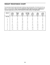
... chart below shows the approximate weight resistance at each station may vary due to differences in individual weight plates as well as friction between the cables, pulleys, and weight guides. WEIGHT Left Top 1 2 3 4 5 6 7 8 HIGH PULLEY (lbs.) 13 27 46 59 74 87 102 115 129 PRESS ARM (lbs.) 20 40 59...
... chart below shows the approximate weight resistance at each station may vary due to differences in individual weight plates as well as friction between the cables, pulleys, and weight guides. WEIGHT Left Top 1 2 3 4 5 6 7 8 HIGH PULLEY (lbs.) 13 27 46 59 74 87 102 115 129 PRESS ARM (lbs.) 20 40 59...
English Manual
Page 24
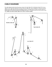
... weight system will not function properly and damage may occur. If the cables have been assembled correctly. Use the diagrams to make sure that the cable traps do not touch or bind the cables. 2 5 4 1 Butterfly Cable (46) 3 4 2 5 3 1 High Cable (45) 6 6 11 Low Cable (47) 7 9 8 10 3 5 4 2 1 24 CABLE DIAGRAMS The cable diagrams below show the correct route for each...
... weight system will not function properly and damage may occur. If the cables have been assembled correctly. Use the diagrams to make sure that the cable traps do not touch or bind the cables. 2 5 4 1 Butterfly Cable (46) 3 4 2 5 3 1 High Cable (45) 6 6 11 Low Cable (47) 7 9 8 10 3 5 4 2 1 24 CABLE DIAGRAMS The cable diagrams below show the correct route for each...
English Manual
Page 30
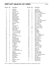
...Inner Cap 42 1 Lat Bar 43 2 Handgrip 44 2 Weight Guide Bushing 45 1 High Cable 46 1 Butterfly Cable 47 1 Low Cable 48 2 Pivot Bracket 49 1 Chain 50 6 3/8" Nylon Jamnut 51 1 Handle 52 3 Cable Clip 53 2 Locking Pin 54 4 Butterfly Cap 55 4 Plastic Washer 56 2 Double ... Adjustment Tube 89 1 5/16" x 2 1/2" Bolt 90 2 1/4" x 2 1/2" Bolt 91 6 Cable Trap 92 2 Pulley Cover 93 1 Ab Strap 94 1 Short Pad Tube 95 1 Leg Press Cable 96 1 Leg Lever Cable 97 2 3/8" x 3" Button Head Bolt 98 1 Rubber Bumper 99 4 Nut Clips # 1 User's ...
...Inner Cap 42 1 Lat Bar 43 2 Handgrip 44 2 Weight Guide Bushing 45 1 High Cable 46 1 Butterfly Cable 47 1 Low Cable 48 2 Pivot Bracket 49 1 Chain 50 6 3/8" Nylon Jamnut 51 1 Handle 52 3 Cable Clip 53 2 Locking Pin 54 4 Butterfly Cap 55 4 Plastic Washer 56 2 Double ... Adjustment Tube 89 1 5/16" x 2 1/2" Bolt 90 2 1/4" x 2 1/2" Bolt 91 6 Cable Trap 92 2 Pulley Cover 93 1 Ab Strap 94 1 Short Pad Tube 95 1 Leg Press Cable 96 1 Leg Lever Cable 97 2 3/8" x 3" Button Head Bolt 98 1 Rubber Bumper 99 4 Nut Clips # 1 User's ...


