
English Manual
Page 11
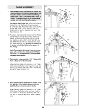
...Retighten the Locknuts when this step, it may be able to hold the Cable in the groove of the weight system, with the Left Top Frame (3) removed for proper cable routing and help identifying the cables. Route the High Cable (45) around a 3 1/2" Pulley (38) and down through the ...Left Top Frame (3) and around a 3 1/2" Pulley (38). the pulleys must be necessary to the CABLE DIAGRAMS and CABLE ID CHART on the Center Top Frame ...
...Retighten the Locknuts when this step, it may be able to hold the Cable in the groove of the weight system, with the Left Top Frame (3) removed for proper cable routing and help identifying the cables. Route the High Cable (45) around a 3 1/2" Pulley (38) and down through the ...Left Top Frame (3) and around a 3 1/2" Pulley (38). the pulleys must be necessary to the CABLE DIAGRAMS and CABLE ID CHART on the Center Top Frame ...
English Manual
Page 13
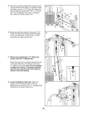
... (62) and a 3/8" Nylon Locknut (70). 38 75 34 81 34 70 75 7 95 36 3 70 62 38 95 27. Attach the end of the Cable, as shown. Attach the 28 Cable to the "U"-Bracket (85) with a 3/8" x 2 3/4" Bolt (81), two 3/8" Washers (75), two 1/2" Spacers (34), and a 3/8" Nylon Locknut (70). 26. Locate ...5/16" Nylon Locknut (71). 71 46 48 78 10 13 Attach the Pulley inside the Upright with a 1/4" Washer (35) and a 1/4" Nylon Locknut (65). Route the Leg Press Cable (95) through the Left 25 Leg (36) and the Left Upright (7) as shown in the inset drawing. 95 35 65 85 95 65 28...
... (62) and a 3/8" Nylon Locknut (70). 38 75 34 81 34 70 75 7 95 36 3 70 62 38 95 27. Attach the end of the Cable, as shown. Attach the 28 Cable to the "U"-Bracket (85) with a 3/8" x 2 3/4" Bolt (81), two 3/8" Washers (75), two 1/2" Spacers (34), and a 3/8" Nylon Locknut (70). 26. Locate ...5/16" Nylon Locknut (71). 71 46 48 78 10 13 Attach the Pulley inside the Upright with a 1/4" Washer (35) and a 1/4" Nylon Locknut (65). Route the Leg Press Cable (95) through the Left 25 Leg (36) and the Left Upright (7) as shown in the inset drawing. 95 35 65 85 95 65 28...
English Manual
Page 15
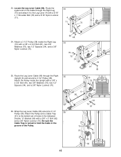
... (34), and a 3/8" Nylon Locknut (70). 96 78 34 70 75 34 73 38 75 34 81 35. Route the Leg Lever Cable (96) through the Right Leg (73) and attach it to hold the Cable in the groove of holes in the indicated Double "U"-Bracket (56) with a 5/16" x 1" Shoulder Bolt (78...) and a 5/16" Nylon Locknut (71). 33 4 71 73 34. Route the eyelet end of the Cable through the Right 35 Upright (6) and around a 3 1/2" 36 Pulley (38). Be sure the Cable Trap is turned to the Leg Lever (4) with a 3/8" x 2" Bolt (62) and a 3/8" Nylon Locknut (70). Locate ...
... (34), and a 3/8" Nylon Locknut (70). 96 78 34 70 75 34 73 38 75 34 81 35. Route the Leg Lever Cable (96) through the Right Leg (73) and attach it to hold the Cable in the groove of holes in the indicated Double "U"-Bracket (56) with a 5/16" x 1" Shoulder Bolt (78...) and a 5/16" Nylon Locknut (71). 33 4 71 73 34. Route the eyelet end of the Cable through the Right 35 Upright (6) and around a 3 1/2" 36 Pulley (38). Be sure the Cable Trap is turned to the Leg Lever (4) with a 3/8" x 2" Bolt (62) and a 3/8" Nylon Locknut (70). Locate ...
English Manual
Page 16
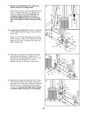
... other "U"-Bracket (85) with a 3/8" x 2" Bolt (62) and a 3/8" Nylon Locknut (70). Route the Low Cable (47) through the cage on the Leg Press Frame (30). Wrap the Low Cable (47) around a 3 1/2" Pulley 40 (38). Locate the Low Cable (47). Route the small ball 38 on the Cable through the Left Leg 39 (36) and the Left Upright...
... other "U"-Bracket (85) with a 3/8" x 2" Bolt (62) and a 3/8" Nylon Locknut (70). Route the Low Cable (47) through the cage on the Leg Press Frame (30). Wrap the Low Cable (47) around a 3 1/2" Pulley 40 (38). Locate the Low Cable (47). Route the small ball 38 on the Cable through the Left Leg 39 (36) and the Left Upright...
English Manual
Page 20
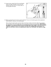
...(9). If one of this manual for proper cable routing. See the CABLE DIAGRAM on the following page. see TIGHTENING THE CABLES on the Pins to remove it by tightening the cables; IMPORTANT: If the cables are not properly routed, they may be explained in the cables, you will be damaged when heavy weight is... used. If there is any slack in ADJUSTMENTS, starting on pages 24 and 25 of the cables does not move smoothly ...
...(9). If one of this manual for proper cable routing. See the CABLE DIAGRAM on the following page. see TIGHTENING THE CABLES on the Pins to remove it by tightening the cables; IMPORTANT: If the cables are not properly routed, they may be explained in the cables, you will be damaged when heavy weight is... used. If there is any slack in ADJUSTMENTS, starting on pages 24 and 25 of the cables does not move smoothly ...
English Manual
Page 24
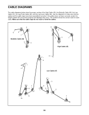
CABLE DIAGRAMS The cable diagrams below show the correct route for each cable. The numbers show the proper routing of the High Cable (45), the Butterfly Cable (46), the Low Cable (47), the Leg Press Cable (95), and the Leg Lever Cable (96). If the cables have been assembled correctly. Make sure that the cables and the cable traps have not been correctly routed, the...
CABLE DIAGRAMS The cable diagrams below show the correct route for each cable. The numbers show the proper routing of the High Cable (45), the Butterfly Cable (46), the Low Cable (47), the Leg Press Cable (95), and the Leg Lever Cable (96). If the cables have been assembled correctly. Make sure that the cables and the cable traps have not been correctly routed, the...


