

English Manual
Page 2
Remove the PART IDENTIFICATION CHART and the PART LIST/EXPLODED DRAWING before beginning assembly. 2 TABLE OF CONTENTS IMPORTANT PRECAUTIONS 3 BEFORE YOU BEGIN 4 ASSEMBLY 5 ADJUSTMENTS 21 WEIGHT RESISTANCE CHART 23 CABLE DIAGRAM 24 EXERCISE GUIDELINES 26 ORDERING REPLACEMENT PARTS Back Cover FULL 90 DAY WARRANTY Back Cover Note: A PART IDENTIFICATION CHART and a PART LIST/EXPLODED DRAWING are attached in the center of this manual.
Remove the PART IDENTIFICATION CHART and the PART LIST/EXPLODED DRAWING before beginning assembly. 2 TABLE OF CONTENTS IMPORTANT PRECAUTIONS 3 BEFORE YOU BEGIN 4 ASSEMBLY 5 ADJUSTMENTS 21 WEIGHT RESISTANCE CHART 23 CABLE DIAGRAM 24 EXERCISE GUIDELINES 26 ORDERING REPLACEMENT PARTS Back Cover FULL 90 DAY WARRANTY Back Cover Note: A PART IDENTIFICATION CHART and a PART LIST/EXPLODED DRAWING are attached in the center of this manual.
English Manual
Page 11
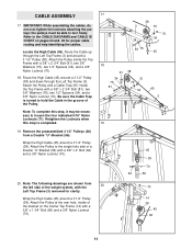
... through the Left Top Frame (3). Wrap the High Cable (45) around a 3 1/2" Pulley (38). IMPORTANT: While assembling the cables, do not over tighten the locknuts attaching the pulleys; the pulleys must be necessary to the CABLE DIAGRAMS and CABLE ID CHART on the Center Top Frame (14) ...34), and a 3/8" Nylon Locknut (70). Refer to loosen the four indicated 5/16" Nylon Locknuts (71). Route the High Cable (45) around a 3 1/2" Pulley (38) and down through the Left Top Frame (3) and around a 3 1/2" Pulley (38). Be sure the Cable Trap is completed. 19. CABLE ASSEMBLY 17.
... through the Left Top Frame (3). Wrap the High Cable (45) around a 3 1/2" Pulley (38). IMPORTANT: While assembling the cables, do not over tighten the locknuts attaching the pulleys; the pulleys must be necessary to the CABLE DIAGRAMS and CABLE ID CHART on the Center Top Frame (14) ...34), and a 3/8" Nylon Locknut (70). Refer to loosen the four indicated 5/16" Nylon Locknuts (71). Route the High Cable (45) around a 3 1/2" Pulley (38) and down through the Left Top Frame (3) and around a 3 1/2" Pulley (38). Be sure the Cable Trap is completed. 19. CABLE ASSEMBLY 17.
English Manual
Page 24
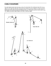
... that the cables and the cable traps have not been correctly routed, the weight system will not function properly and damage may occur. Use the diagrams to make sure that the cable traps do not touch or bind the cables. 2 5 4 1 Butterfly Cable (46) 3 4 2 5 3 1 High Cable (45) 6 6 11 Low Cable (47) 7 9 8 10 3 5 4 2 1 24 If the cables have been assembled correctly.
... that the cables and the cable traps have not been correctly routed, the weight system will not function properly and damage may occur. Use the diagrams to make sure that the cable traps do not touch or bind the cables. 2 5 4 1 Butterfly Cable (46) 3 4 2 5 3 1 High Cable (45) 6 6 11 Low Cable (47) 7 9 8 10 3 5 4 2 1 24 If the cables have been assembled correctly.


