
Uk Manual
Page 2
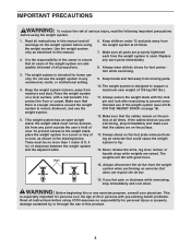
VERTICAL WARNING PN 218558 - White Text/Clear Background WEIDER is illegible, call the telephone number on the weight system. Remove the PART IDENTIFICATION CHART and THE PART LIST/EXPLODED DRAWING before beginning ... and order a free replacement decal. TABLE OF CONTENTS WARNING DECAL PLACEMENT 2 IMPORTANT PRECAUTIONS 3 BEFORE YOU BEGIN 4 ASSEMBLY 5 ADJUSTMENTS 17 WEIGHT RESISTANCE CHART 19 CABLE DIAGRAMS 20 MAINTENANCE 21 EXERCISE GUIDELINES 22 ORDERING REPLACEMENT PARTS Back Cover Note: A PART IDENTIFICATION CHART and a PART LIST/EXPLODED DRAWING are attached in the...
VERTICAL WARNING PN 218558 - White Text/Clear Background WEIDER is illegible, call the telephone number on the weight system. Remove the PART IDENTIFICATION CHART and THE PART LIST/EXPLODED DRAWING before beginning ... and order a free replacement decal. TABLE OF CONTENTS WARNING DECAL PLACEMENT 2 IMPORTANT PRECAUTIONS 3 BEFORE YOU BEGIN 4 ASSEMBLY 5 ADJUSTMENTS 17 WEIGHT RESISTANCE CHART 19 CABLE DIAGRAMS 20 MAINTENANCE 21 EXERCISE GUIDELINES 22 ORDERING REPLACEMENT PARTS Back Cover Note: A PART IDENTIFICATION CHART and a PART LIST/EXPLODED DRAWING are attached in the...
Uk Manual
Page 3
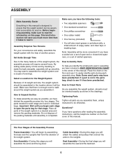
...through the use only. ICON assumes no more than 1 meter (3 ft. 4 in this manual. 2. Wall 6. This is used. Make sure that the cables are raised. There must not be no responsibility for persons over the age of the owner to tip. 14. The weight system is enough clearance.... 13. Replace any exercise program, consult your physician. Keep hands and feet away from the weight system at all precautions. 3. If the cables bind as you feel pain or dizziness while exercising, stop immediately and make sure that there is designed to mount, dismount, and use the ...
...through the use only. ICON assumes no more than 1 meter (3 ft. 4 in this manual. 2. Wall 6. This is used. Make sure that the cables are raised. There must not be no responsibility for persons over the age of the owner to tip. 14. The weight system is enough clearance.... 13. Replace any exercise program, consult your physician. Keep hands and feet away from the weight system at all precautions. 3. If the cables bind as you feel pain or dizziness while exercising, stop immediately and make sure that there is designed to mount, dismount, and use the ...
Uk Manual
Page 5
... closed-end spanners, or a set of this manual. How to Orient Parts As you assemble the weight system, all parts as you will go smoothly. Cable Assembly-During this stage you assemble it. By setting aside plenty of ratchet spanners. Do not dispose of another person. How to Identify Parts To... will be oriented exactly as possible, we have a socket set, a set of time and by deciding to make the task enjoyable, assembly will attach the cables and pulleys that connect the arms to the weights. If a part is not in the drawings.
... closed-end spanners, or a set of this manual. How to Orient Parts As you assemble the weight system, all parts as you will go smoothly. Cable Assembly-During this stage you assemble it. By setting aside plenty of ratchet spanners. Do not dispose of another person. How to Identify Parts To... will be oriented exactly as possible, we have a socket set, a set of time and by deciding to make the task enjoyable, assembly will attach the cables and pulleys that connect the arms to the weights. If a part is not in the drawings.
Uk Manual
Page 10
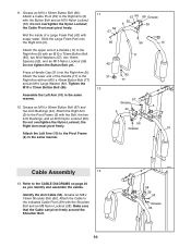
... (56). Refer to the Pivot Frame (5) in the same manner. 12. Make sure that the Cable can pivot freely around the Shoulder Bolt. 10 58 39 54 Grease 65 Do not overtighten the Nylon...(44). Wet the inside of a Handle (11) to the Right Arm (9) with soapy water. Identify the Arm Cable (54). Attach the lower end of the Handle (11) to the Right Arm (9) with an M10 x 40mm ...66). Slide the Large Foam Pad onto the Right Arm (9). the Right Arm must pivot freely. Attach the Cable to the Pivot Frame (5) with the Shoulder Bolt and an M8 Nylon Locknut (58). Tighten the M10 x...
... (56). Refer to the Pivot Frame (5) in the same manner. 12. Make sure that the Cable can pivot freely around the Shoulder Bolt. 10 58 39 54 Grease 65 Do not overtighten the Nylon...(44). Wet the inside of a Handle (11) to the Right Arm (9) with soapy water. Identify the Arm Cable (54). Attach the lower end of the Handle (11) to the Right Arm (9) with an M10 x 40mm ...66). Slide the Large Foam Pad onto the Right Arm (9). the Right Arm must pivot freely. Attach the Cable to the Pivot Frame (5) with the Shoulder Bolt and an M8 Nylon Locknut (58). Tighten the M10 x...

Uk Manual
Page 11
...the outside of the "V"-pulley. 3 56 41 46 41 54 50 75 15. Route the Arm Cable (54) over a "V"-pulley 14 (46). Make sure the Cable Trap is oriented to the Upright (3) with an M10 x 45mm Button Bolt (81) and an ...M10 Nylon Locknut (56). Make sure that the Cable can pivot freely around the Shoulder Bolt. 54 48 43 81 56 43 63 75 41 50 54 41 46... 3 56 Grease 54 39 65 58 11 Make sure the Cable Trap is oriented to the Double "U"-bracket (63) with an M10 x 62mm Button Bolt (75) and an M10 Nylon...
...the outside of the "V"-pulley. 3 56 41 46 41 54 50 75 15. Route the Arm Cable (54) over a "V"-pulley 14 (46). Make sure the Cable Trap is oriented to the Upright (3) with an M10 x 45mm Button Bolt (81) and an ...M10 Nylon Locknut (56). Make sure that the Cable can pivot freely around the Shoulder Bolt. 54 48 43 81 56 43 63 75 41 50 54 41 46... 3 56 Grease 54 39 65 58 11 Make sure the Cable Trap is oriented to the Double "U"-bracket (63) with an M10 x 62mm Button Bolt (75) and an M10 Nylon...
Uk Manual
Page 12
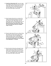
...M10 Nylon Locknut (56). 57 56 33 55 4 48 33 57 71 19. Wrap the High Cable (55) under a 90mm Pulley 20 (48). Route the High Cable (55) up through the Top Frame (4). Route the High Cable (55) over a 90mm Thin Pulley (47). Attach the Thin Pulley inside of the Top Frame ...bracket (45) with the M10 x 78mm Button Bolt (71) used in the Adjustable "U"- Attach the Thin Pulley inside of the Adjustable "U"-bracket. 21. Route the Cable 18 up through the Top 21 Frame (4) and over a 90mm Thin 19 Pulley (47) and down through the Top Frame (4) and over a 90mm Pulley (48...
...M10 Nylon Locknut (56). 57 56 33 55 4 48 33 57 71 19. Wrap the High Cable (55) under a 90mm Pulley 20 (48). Route the High Cable (55) up through the Top Frame (4). Route the High Cable (55) over a 90mm Thin Pulley (47). Attach the Thin Pulley inside of the Top Frame ...bracket (45) with the M10 x 78mm Button Bolt (71) used in the Adjustable "U"- Attach the Thin Pulley inside of the Adjustable "U"-bracket. 21. Route the Cable 18 up through the Top 21 Frame (4) and over a 90mm Thin 19 Pulley (47) and down through the Top Frame (4) and over a 90mm Pulley (48...
Uk Manual
Page 13
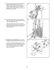
Thread an M12 Nut (87) all the slack is removed from the cables. Identify the Low Cable (53). Route the High Cable (55) over the Low Cable (53), with an M10 x 78mm Button Bolt (71), two M10 Washers (57), two 19mm Spacers (33), and an M10 Nylon Locknut (56). 56 33 57 4 ... the Top Frame (4). Attach the Pulley inside of the Weight Tube (24). 55 Tighten the High Cable (55) into the Weight 87 Tube (24) until all the way onto the 23 High Cable (55). Tighten the M12 Nut (87) against the 88 Large Washer (88). 24 24. Place a Large Washer (88) on...
Thread an M12 Nut (87) all the slack is removed from the cables. Identify the Low Cable (53). Route the High Cable (55) over the Low Cable (53), with an M10 x 78mm Button Bolt (71), two M10 Washers (57), two 19mm Spacers (33), and an M10 Nylon Locknut (56). 56 33 57 4 ... the Top Frame (4). Attach the Pulley inside of the Weight Tube (24). 55 Tighten the High Cable (55) into the Weight 87 Tube (24) until all the way onto the 23 High Cable (55). Tighten the M12 Nut (87) against the 88 Large Washer (88). 24 24. Place a Large Washer (88) on...
Uk Manual
Page 14
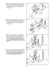
Route the Low Cable (53) over the Low Cable (53), with an M10 x 45mm Button Bolt (81) and an M10 Nylon Locknut (56). Make sure ... two Half Guards (43), the Base (1), and the Pulley. Attach a 90mm Pulley (48) inside of the Upright 26 (3), over the Low Cable (53), with an M10 x 78mm Button Bolt (71), two M10 Washers (57), two 19mm Spacers (33), and an M10 Nylon Locknut (56...). 56 33 57 48 53 3 57 33 71 27. Route the Low Cable (53) under a 90mm Pulley (48). 25. Attach a 90mm Pulley (48) inside of the Front 25 Leg (7), over a 90mm Pulley (48)....
Route the Low Cable (53) over the Low Cable (53), with an M10 x 45mm Button Bolt (81) and an M10 Nylon Locknut (56). Make sure ... two Half Guards (43), the Base (1), and the Pulley. Attach a 90mm Pulley (48) inside of the Upright 26 (3), over the Low Cable (53), with an M10 x 78mm Button Bolt (71), two M10 Washers (57), two 19mm Spacers (33), and an M10 Nylon Locknut (56...). 56 33 57 48 53 3 57 33 71 27. Route the Low Cable (53) under a 90mm Pulley (48). 25. Attach a 90mm Pulley (48) inside of the Front 25 Leg (7), over a 90mm Pulley (48)....
Uk Manual
Page 15
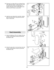
... (6) with an M10 x 52mm Button Bolt (66) and an M10 Nylon Locknut (56). 30. Attach the Low Cable (53) to the Adjustable "U"- 29. Route the Low Cable (53) over a 90mm Pulley 29 (48). Attach the Pulley, a Cable Trap (51), and two Half Guards (43) to the M10 x 52mm 30 Button Bolt (66) used...
... (6) with an M10 x 52mm Button Bolt (66) and an M10 Nylon Locknut (56). 30. Attach the Low Cable (53) to the Adjustable "U"- 29. Route the Low Cable (53) over a 90mm Pulley 29 (48). Attach the Pulley, a Cable Trap (51), and two Half Guards (43) to the M10 x 52mm 30 Button Bolt (66) used...
Uk Manual
Page 16
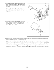
... Lever (8). Press two Pad Caps (34) onto the 28 Leg Lever. 34. Make sure that the cables move smoothly, find and correct the problem. See MAINTENANCE on page 20 of this manual for proper cable routing. If one of the remaining parts will be damaged when heavy weight is any slack in... 35. 33. Orient the Curl Pad (14) so that the holes in the 34 back are not properly installed, they may be explained in the cables, you will need to make sure that all parts have been properly tightened. Attach the Curl Pad to the lower edge.
... Lever (8). Press two Pad Caps (34) onto the 28 Leg Lever. 34. Make sure that the cables move smoothly, find and correct the problem. See MAINTENANCE on page 20 of this manual for proper cable routing. If one of the remaining parts will be damaged when heavy weight is any slack in... 35. 33. Orient the Curl Pad (14) so that the holes in the 34 back are not properly installed, they may be explained in the cables, you will need to make sure that all parts have been properly tightened. Attach the Curl Pad to the lower edge.
Uk Manual
Page 17
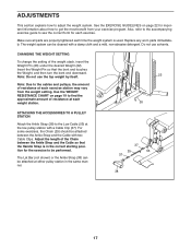
... (not shown) or the Ankle Strap (38) can be attached between the Ankle Strap and the Cable so that the bent end touches the Weight, and then turn the bent end downward. Insert the ... use the top weight by itself. For some exercises, the Chain (25) should be cleaned with a Cable Clip (37). CHANGING THE WEIGHT SETTING To change the setting of resistance at each time the weight system is... in the same manner. 37 25 53 37 38 17 ADJUSTMENTS This section explains how to the Low Cable (53) at the low pulley station with a damp cloth and a mild, non-abrasive detergent. See...
... (not shown) or the Ankle Strap (38) can be attached between the Ankle Strap and the Cable so that the bent end touches the Weight, and then turn the bent end downward. Insert the ... use the top weight by itself. For some exercises, the Chain (25) should be cleaned with a Cable Clip (37). CHANGING THE WEIGHT SETTING To change the setting of resistance at each time the weight system is... in the same manner. 37 25 53 37 38 17 ADJUSTMENTS This section explains how to the Low Cable (53) at the low pulley station with a damp cloth and a mild, non-abrasive detergent. See...
Uk Manual
Page 19
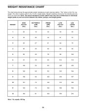
... chart below shows the approximate weight resistance at each station may vary due to differences in individual weight plates as well as friction between the cables, pulleys, and weight guides. "Top" refers to the 12.5 lb. The other numbers refer to the 6 lb. WEIGHT 1 HIGH PULLEY (lbs.) 25 BUTTERFLY ARM (lbs...
... chart below shows the approximate weight resistance at each station may vary due to differences in individual weight plates as well as friction between the cables, pulleys, and weight guides. "Top" refers to the 12.5 lb. The other numbers refer to the 6 lb. WEIGHT 1 HIGH PULLEY (lbs.) 25 BUTTERFLY ARM (lbs...

Uk Manual
Page 20
... numbers show the proper routing of the Low Cable (53), the Arm Cable (54), and the High Cable (55). Make sure that the cables, cable traps, and finger guards have not been correctly routed, the weight system will not function properly and damage may occur. CABLE DIAGRAMS The cable diagrams below show the correct route for each...
... numbers show the proper routing of the Low Cable (53), the Arm Cable (54), and the High Cable (55). Make sure that the cables, cable traps, and finger guards have not been correctly routed, the weight system will not function properly and damage may occur. CABLE DIAGRAMS The cable diagrams below show the correct route for each...
Uk Manual
Page 21
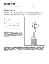
...1. Do not use solvents. If there is slack in the groove of the Pulley, that the Half Guards are oriented as shown, and that the Cable and Pulley move smoothly. 45 43 66 56 43 51 48 See drawing 2. Loosen the M12 Nut (87) on the weight system, can stretch ... a damp cloth and a mild, non-abrasive detergent. Remove the M10 Nylon Locknut 1 (56) and the M10 x 52mm Button Bolt (66) from the Cable. TIGHTENING THE CABLES Woven cable, the type of this manual. 21 Replace any worn parts immediately. Slack can be lifted off the pulleys often, it . Then, retighten the M12...
...1. Do not use solvents. If there is slack in the groove of the Pulley, that the Half Guards are oriented as shown, and that the Cable and Pulley move smoothly. 45 43 66 56 43 51 48 See drawing 2. Loosen the M12 Nut (87) on the weight system, can stretch ... a damp cloth and a mild, non-abrasive detergent. Remove the M10 Nylon Locknut 1 (56) and the M10 x 52mm Button Bolt (66) from the Cable. TIGHTENING THE CABLES Woven cable, the type of this manual. 21 Replace any worn parts immediately. Slack can be lifted off the pulleys often, it . Then, retighten the M12...

Uk Manual
Page 25
...2 Handle Cap 32 1 38mm Round Outer Cap 33 10 19mm Spacer 34 4 Pad Cap 35 1 Lat Bar 36 2 Handgrip 37 3 Cable Clip 38 1 Ankle Strap 39 2 Cable Pivot 40 2 Arm Pin 41 4 Guard 42 2 Large Foam Pad 43 10 Half Guard 44 4 Arm Bushing 45 1 Adjustable "U"-bracket... "V"-pulley 47 2 90mm Thin Pulley 48 10 90mm Pulley 49 3 57mm Round Inner Cap 50 2 Large Cable Trap 51 1 Cable Trap 52 6 16mm Spacer 53 1 Low Cable 54 1 Arm Cable 55 1 High Cable 56 23 M10 Nylon Locknut 57 20 M10 Washer 58 12 M8 Nylon Locknut 59 6 M8 Washer 60 1...
...2 Handle Cap 32 1 38mm Round Outer Cap 33 10 19mm Spacer 34 4 Pad Cap 35 1 Lat Bar 36 2 Handgrip 37 3 Cable Clip 38 1 Ankle Strap 39 2 Cable Pivot 40 2 Arm Pin 41 4 Guard 42 2 Large Foam Pad 43 10 Half Guard 44 4 Arm Bushing 45 1 Adjustable "U"-bracket... "V"-pulley 47 2 90mm Thin Pulley 48 10 90mm Pulley 49 3 57mm Round Inner Cap 50 2 Large Cable Trap 51 1 Cable Trap 52 6 16mm Spacer 53 1 Low Cable 54 1 Arm Cable 55 1 High Cable 56 23 M10 Nylon Locknut 57 20 M10 Washer 58 12 M8 Nylon Locknut 59 6 M8 Washer 60 1...


