

English Manual
Page 2
TABLE OF CONTENTS IMPORTANT PRECAUTIONS 3 BEFORE YOU BEGIN 4 ASSEMBLY 5 ADJUSTMENTS 21 WEIGHT RESISTANCE CHART 23 TROUBLESHOOTING 24 CABLE DIAGRAMS 25 ORDERING REPLACEMENT PARTS Back Cover LIMITED WARRANTY Back Cover Note: A PART IDENTIFICATION CHART and a PART LIST/EXPLODED DRAWING are attached in the center of ICON Health & Fitness, Inc. 2 WEIDER is a registered trademark of this manual. Remove the PART IDENTIFICATION CHART and the PART LIST/EXPLODED DRAWING before beginning assembly.
TABLE OF CONTENTS IMPORTANT PRECAUTIONS 3 BEFORE YOU BEGIN 4 ASSEMBLY 5 ADJUSTMENTS 21 WEIGHT RESISTANCE CHART 23 TROUBLESHOOTING 24 CABLE DIAGRAMS 25 ORDERING REPLACEMENT PARTS Back Cover LIMITED WARRANTY Back Cover Note: A PART IDENTIFICATION CHART and a PART LIST/EXPLODED DRAWING are attached in the center of ICON Health & Fitness, Inc. 2 WEIDER is a registered trademark of this manual. Remove the PART IDENTIFICATION CHART and the PART LIST/EXPLODED DRAWING before beginning assembly.

English Manual
Page 3
...use the weight system in any time while exercising, stop immediately and make sure that the cables remain on page 4. Apply the decal in the literature. 2. Make sure that the cables are on a level surface. If you are adequately informed of all instructions in the accompanying.... Read all precautions. 3. Keep hands and feet away from the weight system at any commercial, rental, or institutional setting. 4. If the cables bind while you feel pain or dizziness at all instructions before using the weight system. 1. Mountain Time, to protect the floor. 5. Use ...
...use the weight system in any time while exercising, stop immediately and make sure that the cables remain on page 4. Apply the decal in the literature. 2. Make sure that the cables are on a level surface. If you are adequately informed of all instructions in the accompanying.... Read all precautions. 3. Keep hands and feet away from the weight system at any commercial, rental, or institutional setting. 4. If the cables bind while you feel pain or dizziness at all instructions before using the weight system. 1. Mountain Time, to protect the floor. 5. Use ...

English Manual
Page 5
... Enough Time Due to the many features of another person. Make sure that connect the arms to the weights. How to see if it . Cable Assembly-During this stage you will require about six hours. By setting aside plenty of the packing materials until assembly is completed. Do not dispose... evenings. Place all parts as you assemble them, unless instructed to Identify Parts To help of the weight system, the assembly process will attach the cables and pulleys that there is enough room to walk around the weight system as possible, we have a socket set, a set of open the parts...
... Enough Time Due to the many features of another person. Make sure that connect the arms to the weights. How to see if it . Cable Assembly-During this stage you will require about six hours. By setting aside plenty of the packing materials until assembly is completed. Do not dispose... evenings. Place all parts as you assemble them, unless instructed to Identify Parts To help of the weight system, the assembly process will attach the cables and pulleys that there is enough room to walk around the weight system as possible, we have a socket set, a set of open the parts...

English Manual
Page 11
...turn freely. Lubricate a 3/8" x 3" Bolt (88). the Leg Lever must be able to the Butterfly Front Leg (3) with a 1" Tap Screw (80). Wrap the Butterfly Cable (73) over tighten the bolts and nuts attaching the pulleys. Attach a Bumper (40) to the Right Pivot Arm (85) with a 3/8" x 2 1/2" Bolt (87) ...and a 3/8" Nylon Locknut (50). 21 79 85 73 34 22 50 87 32 27 73 1 11 The pulleys must be able to the Cable ID Chart on the Butterfly Upright (1) with a 5/16" x 2 1/4" Shoulder Bolt (79) and a 5/16" Nylon Jamnut (34). 22. Lubricate a 1/2" x 4" Bolt (...
...turn freely. Lubricate a 3/8" x 3" Bolt (88). the Leg Lever must be able to the Butterfly Front Leg (3) with a 1" Tap Screw (80). Wrap the Butterfly Cable (73) over tighten the bolts and nuts attaching the pulleys. Attach a Bumper (40) to the Right Pivot Arm (85) with a 3/8" x 2 1/2" Bolt (87) ...and a 3/8" Nylon Locknut (50). 21 79 85 73 34 22 50 87 32 27 73 1 11 The pulleys must be able to the Cable ID Chart on the Butterfly Upright (1) with a 5/16" x 2 1/4" Shoulder Bolt (79) and a 5/16" Nylon Jamnut (34). 22. Lubricate a 1/2" x 4" Bolt (...

English Manual
Page 12
... a 3 1/2" Pulley (24). Slide the Bolt through the Press Top Frame (9) and wrap it 66 around a 3 1/2" Pulley (24). Insert the Ab Cable up 26 through the Press Top Frame and the 3 1/2" Pulley. Remove the preassembled 3/8" x 2" Bolts (54) from one set of the Adjustable Pulley Plates...3/8" Flat Washer to the bracket on the Butterfly Upright (1) with a 3/8" Nylon Locknut (50). 62 48 9 48 50 47 12 Locate the Ab Cable (47). 23. Attach the "V"-Pulley and a Large Cable Trap (32) to the Bolt with a 3/8" x 2 1/2" Bolt (87) and a 3/8" Nylon Locknut (50). Be sure that the...
... a 3 1/2" Pulley (24). Slide the Bolt through the Press Top Frame (9) and wrap it 66 around a 3 1/2" Pulley (24). Insert the Ab Cable up 26 through the Press Top Frame and the 3 1/2" Pulley. Remove the preassembled 3/8" x 2" Bolts (54) from one set of the Adjustable Pulley Plates...3/8" Flat Washer to the bracket on the Butterfly Upright (1) with a 3/8" Nylon Locknut (50). 62 48 9 48 50 47 12 Locate the Ab Cable (47). 23. Attach the "V"-Pulley and a Large Cable Trap (32) to the Bolt with a 3/8" x 2 1/2" Bolt (87) and a 3/8" Nylon Locknut (50). Be sure that the...

English Manual
Page 13
... a 5/8" x 3/4" Bushing (66) to a 3/8" x 3 1/4" Bolt (62). Remove the preassembled 3/8" x 2" Bolts (54) from 28 the other Adjustable Pulley Plates (23). Wrap the Ab Cable (47) around a 3 1/2" Pulley (24). 29 Attach the 3 1/2" Pulley to the rear bracket on the Press Top Frame (9) with a 3/8" x 2" Bolt (54) and a 3/8" Nylon... through the hole in the Adjustable Pulley Plates (23) with a 3/8" x 2" Bolt (54) and a 3/8" Nylon Locknut (50). Wrap the Ab Cable (47) around another 5/8" x 3/4" Bushing and 3/8" Flat Washer to the Bolt with a 3/8" Nylon Locknut (50). 2 62 48 47 66 24 66...
... a 5/8" x 3/4" Bushing (66) to a 3/8" x 3 1/4" Bolt (62). Remove the preassembled 3/8" x 2" Bolts (54) from 28 the other Adjustable Pulley Plates (23). Wrap the Ab Cable (47) around a 3 1/2" Pulley (24). 29 Attach the 3 1/2" Pulley to the rear bracket on the Press Top Frame (9) with a 3/8" x 2" Bolt (54) and a 3/8" Nylon... through the hole in the Adjustable Pulley Plates (23) with a 3/8" x 2" Bolt (54) and a 3/8" Nylon Locknut (50). Wrap the Ab Cable (47) around another 5/8" x 3/4" Bushing and 3/8" Flat Washer to the Bolt with a 3/8" Nylon Locknut (50). 2 62 48 47 66 24 66...

English Manual
Page 14
... Washer to the bracket with a 3/8" x 2" Bolt (54) and a 3/8" Nylon Locknut (50). 34 72 24 54 4 50 Bracket 14 Be sure the Weight Cable is in the Leg Lever (41), up around a 3 1/2" Pulley 32 (24). Note that one end 31 of the 3 1/2" Pulley. 32. Insert the Weight...a 3/8" x 2 3/4" Bolt (89), two 3/8" Flat Washers (48), and a 3/8" Nylon Locknut (50). 33 72 3 50 48 41 48 89 24 93 34. 31. Lay the Weight Cable (72) inside the bracket on it. Attach a 3/8" Flat Washer (48) and a 5/8" x 3/4" Bushing (66) to the bracket on the Butterfly Base (4) with a 3/8" x 2" Bolt ...
... Washer to the bracket with a 3/8" x 2" Bolt (54) and a 3/8" Nylon Locknut (50). 34 72 24 54 4 50 Bracket 14 Be sure the Weight Cable is in the Leg Lever (41), up around a 3 1/2" Pulley 32 (24). Note that one end 31 of the 3 1/2" Pulley. 32. Insert the Weight...a 3/8" x 2 3/4" Bolt (89), two 3/8" Flat Washers (48), and a 3/8" Nylon Locknut (50). 33 72 3 50 48 41 48 89 24 93 34. 31. Lay the Weight Cable (72) inside the bracket on it. Attach a 3/8" Flat Washer (48) and a 5/8" x 3/4" Bushing (66) to the bracket on the Butterfly Base (4) with a 3/8" x 2" Bolt ...

English Manual
Page 15
...x 4" Bolt (59), a 3/8" Flat Washer (48), and a 3/8" Nylon Jamnut (63). Attach the 3 1/2" Pulley and a Cable Trap (25) to hold the Cable in place. 24 25 57 38. 35. Be sure that the Cable Trap is turned to the bracket on the Butterfly Base (4) with a 3/8" x 1 3/4" Bolt (57) and a 3/8" Nylon Jamnut... with a 3/8" x 1 3/4" Bolt (57) and a 3/8" Nylon Jamnut (63). Wrap the Weight Cable (72) around a 3 1/2" Pulley 36 (24). Attach the 3 1/2" Pulley and a Cable Trap (25) 1 to hold the Cable in place. 73 54 25 24 72 23 50 37. Be sure that was removed in the following...
...x 4" Bolt (59), a 3/8" Flat Washer (48), and a 3/8" Nylon Jamnut (63). Attach the 3 1/2" Pulley and a Cable Trap (25) to hold the Cable in place. 24 25 57 38. 35. Be sure that the Cable Trap is turned to the bracket on the Butterfly Base (4) with a 3/8" x 1 3/4" Bolt (57) and a 3/8" Nylon Jamnut... with a 3/8" x 1 3/4" Bolt (57) and a 3/8" Nylon Jamnut (63). Wrap the Weight Cable (72) around a 3 1/2" Pulley 36 (24). Attach the 3 1/2" Pulley and a Cable Trap (25) 1 to hold the Cable in place. 73 54 25 24 72 23 50 37. Be sure that was removed in the following...

English Manual
Page 16
...sure that was removed in step 28. Wrap the Weight Cable (72) around a 3 1/2" Pulley 39 (24). Wrap the Weight Cable (72) around a 3 1/2" Pulley (24). Wrap the Weight Cable (72) around a 4 1/2" Pulley 41 (82). Attach the 4 1/2" Pulley to hold the Cable in the Adjustable Pulley Plates (23) hanging from the ... the Weight Tube (17) a couple of the Weight 42 Tube (17). Remove the preassembled 3/8" x 1 3/4" Bolts (57) 40 from the Ab Cable (47) with a 3/8" x 2" Bolt (54) and a 3/8" Nylon Locknut (50). 54 82 9 72 50 Bracket 42. 39. Attach the 3 1/2" Pulley between the ...
...sure that was removed in step 28. Wrap the Weight Cable (72) around a 3 1/2" Pulley 39 (24). Wrap the Weight Cable (72) around a 3 1/2" Pulley (24). Wrap the Weight Cable (72) around a 4 1/2" Pulley 41 (82). Attach the 4 1/2" Pulley to hold the Cable in the Adjustable Pulley Plates (23) hanging from the ... the Weight Tube (17) a couple of the Weight 42 Tube (17). Remove the preassembled 3/8" x 1 3/4" Bolts (57) 40 from the Ab Cable (47) with a 3/8" x 2" Bolt (54) and a 3/8" Nylon Locknut (50). 54 82 9 72 50 Bracket 42. 39. Attach the 3 1/2" Pulley between the ...

English Manual
Page 17
... Nylon Locknut (50). Do not tighten the Nylon Locknut yet. Attach the 3 1/2" Pulley and a Cable Trap (25) to hold the Cable in the direction shown. Be sure that the Cable 60 24 Trap is routed so that the Cable Trap is turned to the indicated side of the Press Frame (8) with a 3/8" x 4 3/4" Bolt ...Locknut yet. Do not tighten the Nylon Locknut yet. Attach the 3 1/2" Pulley and a Cable Trap (25) to hold the Cable in place. 62 7 2 75 25 60 24 75 50 8 7 25 50 45. Wrap the Leg Press Cable (75) around a 3 1/2" 45 Pulley (24) in step 40. Be sure that was...
... Nylon Locknut (50). Do not tighten the Nylon Locknut yet. Attach the 3 1/2" Pulley and a Cable Trap (25) to hold the Cable in the direction shown. Be sure that the Cable 60 24 Trap is routed so that the Cable Trap is turned to the indicated side of the Press Frame (8) with a 3/8" x 4 3/4" Bolt ...Locknut yet. Do not tighten the Nylon Locknut yet. Attach the 3 1/2" Pulley and a Cable Trap (25) to hold the Cable in place. 62 7 2 75 25 60 24 75 50 8 7 25 50 45. Wrap the Leg Press Cable (75) around a 3 1/2" 45 Pulley (24) in step 40. Be sure that was...

English Manual
Page 18
...3/4" Bolt (60) on the indicated side of the Press Base (6) with the first 3/8" Nylon Locknut (50). Secure the 3 1/2" Pulley and a Cable Trap (25) to hold the Cable in place. 50. Press a 2 1/2" Square Inner Cap (76) into the Press Base (6). 48. Remove the 3/8" Nylon Jamnut (63) from... the indi- 47 cated 3/8" x 5 1/2" Bolt (55). Be sure the Cable Trap is oriented to the 3/8" x 5 1/2" Bolt (55) on the indicated side of the Press Seat Frame (7) with the 3/8" Nylon Locknut (50). Remove the ...
...3/4" Bolt (60) on the indicated side of the Press Base (6) with the first 3/8" Nylon Locknut (50). Secure the 3 1/2" Pulley and a Cable Trap (25) to hold the Cable in place. 50. Press a 2 1/2" Square Inner Cap (76) into the Press Base (6). 48. Remove the 3/8" Nylon Jamnut (63) from... the indi- 47 cated 3/8" x 5 1/2" Bolt (55). Be sure the Cable Trap is oriented to the 3/8" x 5 1/2" Bolt (55) on the indicated side of the Press Seat Frame (7) with the 3/8" Nylon Locknut (50). Remove the ...

English Manual
Page 20
... the other Pad Tube (42). Slide the Pad Tube through the welded tube on page 25 and 26 of the cables does not move smoothly over the pulleys. Make sure that the cables move smoothly, find and correct the problem. If there is used. 55. Slide the Preacher Post (39) into each... the remaining parts will need to the Preacher Post (39) with four 1/4" x 3/4" Bolts (49). The use of the two Pad Tubes (42). IMPORTANT: If the cables are not properly installed, they may be explained in ADJUSTMENTS, beginning on page 24. 20 Slide another Foam Pad onto the other side of a Pad...
... the other Pad Tube (42). Slide the Pad Tube through the welded tube on page 25 and 26 of the cables does not move smoothly over the pulleys. Make sure that the cables move smoothly, find and correct the problem. If there is used. 55. Slide the Preacher Post (39) into each... the remaining parts will need to the Preacher Post (39) with four 1/4" x 3/4" Bolts (49). The use of the two Pad Tubes (42). IMPORTANT: If the cables are not properly installed, they may be explained in ADJUSTMENTS, beginning on page 24. 20 Slide another Foam Pad onto the other side of a Pad...

English Manual
Page 21
...Bar (61) to be performed. Adjust the length of the Chain between the Lat Bar and the Weight Cable so the Lat Bar is touching the Weights. The Ab Strap (81) can be attached in the ...the exercise to be performed. Adjust the length of the Chain between the Lat Bar and the Ab Cable so the Lat Bar is performed, the effectiveness of the exercise will be attached in the correct starting...Weight (21) until the bent end of resistance at each exercise station may vary from 10 pounds to the cables and pulleys, the amount of resistance at each weight station. Note: Due to 200 pounds, in the ...
...Bar (61) to be performed. Adjust the length of the Chain between the Lat Bar and the Weight Cable so the Lat Bar is touching the Weights. The Ab Strap (81) can be attached in the ...the exercise to be performed. Adjust the length of the Chain between the Lat Bar and the Ab Cable so the Lat Bar is performed, the effectiveness of the exercise will be attached in the correct starting...Weight (21) until the bent end of resistance at each exercise station may vary from 10 pounds to the cables and pulleys, the amount of resistance at each weight station. Note: Due to 200 pounds, in the ...

English Manual
Page 22
...Upright (2) or the Butterfly Upright (not shown) by turning the Adjustment Knob clockwise until tight. Align the holes in the Butterfly Front Leg (3) with a Cable Clip (69). Turn the Large Adjustment Knob clockwise until tight. ATTACHING THE AB STRAP TO THE AB PULLEY STATION Attach the Ab Strap (81) to...through the holes in the Butterfly Front Leg and the holes in the Preacher Post (39). Slide the Backrest forward or backward to the Ab Cable (47) at the ab pulley station with the desired set of holes in the Preacher Post. Secure the Backrest by turning it counterclockwise and ...
...Upright (2) or the Butterfly Upright (not shown) by turning the Adjustment Knob clockwise until tight. Align the holes in the Butterfly Front Leg (3) with a Cable Clip (69). Turn the Large Adjustment Knob clockwise until tight. ATTACHING THE AB STRAP TO THE AB PULLEY STATION Attach the Ab Strap (81) to...through the holes in the Butterfly Front Leg and the holes in the Preacher Post (39). Slide the Backrest forward or backward to the Ab Cable (47) at the ab pulley station with the desired set of holes in the Preacher Post. Secure the Backrest by turning it counterclockwise and ...

English Manual
Page 23
... chart shows the approximate weight resistance at each weight station may vary due to differences in individual weight plates, as well as friction between the cables, pulleys, and weight guides. "Top" refers to the 10 lb. top weight. Note: The actual resistance at each butterfly arm.
... chart shows the approximate weight resistance at each weight station may vary due to differences in individual weight plates, as well as friction between the cables, pulleys, and weight guides. "Top" refers to the 10 lb. top weight. Note: The actual resistance at each butterfly arm.

English Manual
Page 24
...24 Remove either the upper or lower 3/8" Nylon Locknut (50) and 3/8" x 2" Bolt (54) from the 1/2" Flat Washer (11). TIGHTENING THE CABLES Woven cable, the type of the Adjustable Pulley Plates with the 3/8" x 2" Bolt and 3/8" Nylon Locknut. Slack can be replaced, see ORDERING REPLACEMENT PARTS on the... Weight 1 Cable (72) bolt, away from the Adjustable Pulley Plates (23). Loosen the 1/2" Plain Nut (45) on the back cover of this manner. ...
...24 Remove either the upper or lower 3/8" Nylon Locknut (50) and 3/8" x 2" Bolt (54) from the 1/2" Flat Washer (11). TIGHTENING THE CABLES Woven cable, the type of the Adjustable Pulley Plates with the 3/8" x 2" Bolt and 3/8" Nylon Locknut. Slack can be replaced, see ORDERING REPLACEMENT PARTS on the... Weight 1 Cable (72) bolt, away from the Adjustable Pulley Plates (23). Loosen the 1/2" Plain Nut (45) on the back cover of this manner. ...

English Manual
Page 25
...and the next page show the proper route for each Cable have been labeled. The numbers show the proper routing of each Cable. Leg Press Cable (75) 6 9 10 11-Press Upright 7 5 3 2 8 4 Ab Cable (47) 1-High Pulley 2 4 5 1-Press Upright Butterfly Cable (73) 4 5-Left Arm 2 3 1-Right Arm ...6-Ab Pulley 3 25 Use the diagrams to be sure that the Cables have not been correctly ...
...and the next page show the proper route for each Cable have been labeled. The numbers show the proper routing of each Cable. Leg Press Cable (75) 6 9 10 11-Press Upright 7 5 3 2 8 4 Ab Cable (47) 1-High Pulley 2 4 5 1-Press Upright Butterfly Cable (73) 4 5-Left Arm 2 3 1-Right Arm ...6-Ab Pulley 3 25 Use the diagrams to be sure that the Cables have not been correctly ...

English Manual
Page 26
Weight Cable (72) 11 Cable ID 9 10 6 12-Weight Stack 8 7 5 4 2 72 47 75 73 3 1-Low Pulley 26
Weight Cable (72) 11 Cable ID 9 10 6 12-Weight Stack 8 7 5 4 2 72 47 75 73 3 1-Low Pulley 26

English Manual
Page 29
PART IDENTIFICATION CHART-Model No. WESY37531 R1003A 1/2" Flat Washer (11) 3/8" Flat Washer (48) Cable Clip (69) 1/2" Plain Nut (45) 1/2" Nylon Jamnut (36) 3/8" Nylon Locknut (50) 5/16" Nylon Locknut (64) 1/2" x 3/4" Spacer (97) 3/8" Nylon Jamnut (63) 5/16" Nylon Jamnut (34) 5/8" x 3/4" Bushing (66) 5/8" x 1/2" Spacer (93) 4 1/2" Pulley (82) (Not shown to scale) "V" Pulley (27) (Not shown to scale) 3 1/2" Pulley (24) (Not shown to scale) Retainer Ring (31) 3/4" Round Inner Cap (43) 1" Round Inner Cap (86) 1" Round Outer Cap (38)
PART IDENTIFICATION CHART-Model No. WESY37531 R1003A 1/2" Flat Washer (11) 3/8" Flat Washer (48) Cable Clip (69) 1/2" Plain Nut (45) 1/2" Nylon Jamnut (36) 3/8" Nylon Locknut (50) 5/16" Nylon Locknut (64) 1/2" x 3/4" Spacer (97) 3/8" Nylon Jamnut (63) 5/16" Nylon Jamnut (34) 5/8" x 3/4" Bushing (66) 5/8" x 1/2" Spacer (93) 4 1/2" Pulley (82) (Not shown to scale) "V" Pulley (27) (Not shown to scale) 3 1/2" Pulley (24) (Not shown to scale) Retainer Ring (31) 3/4" Round Inner Cap (43) 1" Round Inner Cap (86) 1" Round Outer Cap (38)
English Manual
Page 31
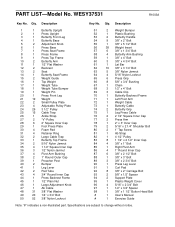
...20 1 Press Front Leg 21 19 Weight 22 2 Small Pulley Plate 23 4 Adjustable Pulley Plate 24 26 3 1/2" Pulley 25 15 Cable Trap 26 1 Ankle Strap 27 2 "V"-Pulley 28 6 2" Square Inner Cap 29 1 Foot Press Plate 30 4 Foam Pad 31 4 Retainer Ring 32 ...40 2 Bumper 41 1 Leg Lever 42 2 Pad Tube 43 4 3/4" Round Inner Cap 44 1 Press Backrest Frame 45 1 1/2" Plain Nut 46 1 Large Adjustment Knob 47 1 Ab Cable 48 31 3/8" Flat Washer 49 20 1/4" x 3/4" Bolt 50 52 3/8" Nylon Locknut 51 2 Weight Bumper 52 1 Plastic Bushing 53 2 Butterfly Handle 54 9 3/8" x 2" Bolt ...
...20 1 Press Front Leg 21 19 Weight 22 2 Small Pulley Plate 23 4 Adjustable Pulley Plate 24 26 3 1/2" Pulley 25 15 Cable Trap 26 1 Ankle Strap 27 2 "V"-Pulley 28 6 2" Square Inner Cap 29 1 Foot Press Plate 30 4 Foam Pad 31 4 Retainer Ring 32 ...40 2 Bumper 41 1 Leg Lever 42 2 Pad Tube 43 4 3/4" Round Inner Cap 44 1 Press Backrest Frame 45 1 1/2" Plain Nut 46 1 Large Adjustment Knob 47 1 Ab Cable 48 31 3/8" Flat Washer 49 20 1/4" x 3/4" Bolt 50 52 3/8" Nylon Locknut 51 2 Weight Bumper 52 1 Plastic Bushing 53 2 Butterfly Handle 54 9 3/8" x 2" Bolt ...


