
User Manual
Page 2
Remove the PART IDENTIFICATION CHART and the PART LIST/EXPLODED DRAWING before beginning assembly. TABLE OF CONTENTS IMPORTANT PRECAUTIONS 3 BEFORE YOU BEGIN 4 ASSEMBLY 5 ADJUSTMENTS 22 WEIGHT RESISTANCE CHART 24 MAINTENANCE 25 CABLE DIAGRAMS 26 ORDERING REPLACEMENT PARTS Back Cover LIMITED WARRANTY Back Cover Note: A PART IDENTIFICATION CHART and a PART LIST/EXPLODED DRAWING are attached in the center of ICON IP, Inc. 2 WEIDER is a registered trademark of this manual.
Remove the PART IDENTIFICATION CHART and the PART LIST/EXPLODED DRAWING before beginning assembly. TABLE OF CONTENTS IMPORTANT PRECAUTIONS 3 BEFORE YOU BEGIN 4 ASSEMBLY 5 ADJUSTMENTS 22 WEIGHT RESISTANCE CHART 24 MAINTENANCE 25 CABLE DIAGRAMS 26 ORDERING REPLACEMENT PARTS Back Cover LIMITED WARRANTY Back Cover Note: A PART IDENTIFICATION CHART and a PART LIST/EXPLODED DRAWING are attached in the center of ICON IP, Inc. 2 WEIDER is a registered trademark of this manual.
User Manual
Page 3
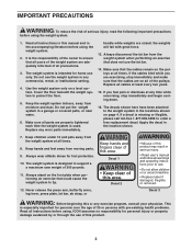
...or persons with great force. 13. Make sure that the cables remain on the foot plate when performing an exercise that all users of the weight system are on or around machine. • Replace label if damaged, illegible, or removed. 12. If the cables bind while you feel ...pain or dizziness at all instructions before using the weight system. 2. Decal 2 ! Keep the weight system indoors, away from moving parts. 9. If you are exercising, stop immediately and begin cooling down. 16. Keep hands and fingers...
...or persons with great force. 13. Make sure that the cables remain on the foot plate when performing an exercise that all users of the weight system are on or around machine. • Replace label if damaged, illegible, or removed. 12. If the cables bind while you feel ...pain or dizziness at all instructions before using the weight system. 2. Decal 2 ! Keep the weight system indoors, away from moving parts. 9. If you are exercising, stop immediately and begin cooling down. 16. Keep hands and fingers...
User Manual
Page 4
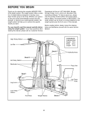
...designed to develop every major muscle group of this manual). Whether your goal is WESY26331. For your cardiovascular system, the weight system will help us assist you have questions after reading this manual carefully before calling. Mountain Time (excluding holidays). The ...labeled. To help you to the weight system (see the front cover of the body. until 6 p.m. BEFORE YOU BEGIN Thank you want. The serial number can be found on a decal attached to achieve the specific results you for selecting the versatile WEIDER® PRO 3750 weight system. Length: 70 in . ...
...designed to develop every major muscle group of this manual). Whether your goal is WESY26331. For your cardiovascular system, the weight system will help us assist you have questions after reading this manual carefully before calling. Mountain Time (excluding holidays). The ...labeled. To help you to the weight system (see the front cover of the body. until 6 p.m. BEFORE YOU BEGIN Thank you want. The serial number can be found on a decal attached to achieve the specific results you for selecting the versatile WEIDER® PRO 3750 weight system. Length: 70 in . ...
User Manual
Page 5
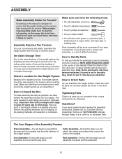
...have divided the assembly process into four stages. If a part is not in individual bags. How to Orient Parts As you assemble the weight system, make assembly as easy as you assemble it . Questions? Cable Assembly-During this stage you will attach the cables and pulleys that...you will require several hours. ASSEMBLY Make Assembly Easier for Yourself Everything in this manual is designed to ensure that form the skeleton of the weight system. this brief introduction will also need grease or petroleum jelly, a small amount of another person. Make sure you have a socket set,...
...have divided the assembly process into four stages. If a part is not in individual bags. How to Orient Parts As you assemble the weight system, make assembly as easy as you assemble it . Questions? Cable Assembly-During this stage you will attach the cables and pulleys that...you will require several hours. ASSEMBLY Make Assembly Easier for Yourself Everything in this manual is designed to ensure that form the skeleton of the weight system. this brief introduction will also need grease or petroleum jelly, a small amount of another person. Make sure you have a socket set,...
User Manual
Page 6
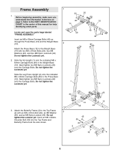
... Carriage Bolts. Do not tighten the Locknuts yet. 49 1 20 13 40 49 4 40 3. Before beginning assembly, make sure you understand the information in the Weight Base (14). Do not tighten the Locknuts yet. 2. Slide the Leg Press Upright (4) onto the indicated M8 x 63mm Carriage Bolts (49) in the center of...." Do not tighten the Locknut yet. Insert six M8 x 63mm Carriage Bolts (49) up through the Press Base (13) and the Weight Base (14). 2 Attach the Press Base (13) to the Weight Base (14) with an M8 x 67mm Bolt (55), an M8 Washer (20), and an M8 Nylon Locknut (40). Hand tighten...
... Carriage Bolts. Do not tighten the Locknuts yet. 49 1 20 13 40 49 4 40 3. Before beginning assembly, make sure you understand the information in the Weight Base (14). Do not tighten the Locknuts yet. 2. Slide the Leg Press Upright (4) onto the indicated M8 x 63mm Carriage Bolts (49) in the center of...." Do not tighten the Locknut yet. Insert six M8 x 63mm Carriage Bolts (49) up through the Press Base (13) and the Weight Base (14). 2 Attach the Press Base (13) to the Weight Base (14) with an M8 x 67mm Bolt (55), an M8 Washer (20), and an M8 Nylon Locknut (40). Hand tighten...
User Manual
Page 7
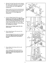
... (8) to the Base with 23 an M8 x 152mm Bolt (67), two 13mm x 19mm Tall Spacers (69), and an M8 Nylon Locknut (40). Make sure the Weight Guides are oriented with two M8 x 67mm Bolts (55), two M8 Washers (20), and two M8 Nylon Locknuts (40). Make sure that the pins on... 40 8 4 40 13 49 5. Do not tighten the Locknuts yet. 4. Attach the lower ends of the 5 brackets on the indicated side of each stack of Weights (90). Hand tighten two M8 Nylon Locknuts (40) onto the Carriage Bolts. Slide the Front Seat Frame (8) onto the indicated M8 x 63mm Carriage Bolts (49...
... (8) to the Base with 23 an M8 x 152mm Bolt (67), two 13mm x 19mm Tall Spacers (69), and an M8 Nylon Locknut (40). Make sure the Weight Guides are oriented with two M8 x 67mm Bolts (55), two M8 Washers (20), and two M8 Nylon Locknuts (40). Make sure that the pins on... 40 8 4 40 13 49 5. Do not tighten the Locknuts yet. 4. Attach the lower ends of the 5 brackets on the indicated side of each stack of Weights (90). Hand tighten two M8 Nylon Locknuts (40) onto the Carriage Bolts. Slide the Front Seat Frame (8) onto the indicated M8 x 63mm Carriage Bolts (49...
User Manual
Page 8
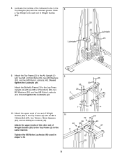
... holes in the 8 Top Weights (24) with an M8 x 152mm Bolt (67), two 13mm x 19mm Spacers (69), and an M8 Nylon Locknut (40). Lubricate the insides of Weight Guides (23) to the Top Frame (2) with the included grease. Slide a Top Weight onto each set of Weight Guides (23). Attach the ...upper ends of one set of Weight Guides (23) to the Top Frame (2) in steps 1-10. 1 40...
... holes in the 8 Top Weights (24) with an M8 x 152mm Bolt (67), two 13mm x 19mm Spacers (69), and an M8 Nylon Locknut (40). Lubricate the insides of Weight Guides (23) to the Top Frame (2) with the included grease. Slide a Top Weight onto each set of Weight Guides (23). Attach the ...upper ends of one set of Weight Guides (23) to the Top Frame (2) in steps 1-10. 1 40...
User Manual
Page 13
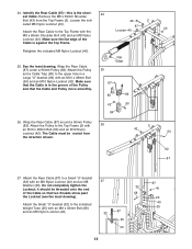
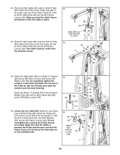
cated M8 Nylon Locknut (40). Wrap the Rear Cable (87) around a 90mm Pulley (82). Attach the Small "U"-bracket (32) to the indicated Weight Tube (25) with 26 an M10 x 48mm Bolt (50) and an M10 Nylon Locknut (42). Identify the Rear Cable (87)-this is against the Top ...
cated M8 Nylon Locknut (40). Wrap the Rear Cable (87) around a 90mm Pulley (82). Attach the Small "U"-bracket (32) to the indicated Weight Tube (25) with 26 an M10 x 48mm Bolt (50) and an M10 Nylon Locknut (42). Identify the Rear Cable (87)-this is against the Top ...
User Manual
Page 18
... Upright (1) with an M8 x 45mm Bolt (68) and an M8 Nylon Locknut (40). 46. Attach the Pulley and both Pulley Covers (94) to the indicated Weight Tube (25) with the M10 x 97mm Bolt (95), two M10 Washers (38), and an M10 Nylon Locknut (42). the Pulley should be down 31 44...
... Upright (1) with an M8 x 45mm Bolt (68) and an M8 Nylon Locknut (40). 46. Attach the Pulley and both Pulley Covers (94) to the indicated Weight Tube (25) with the M10 x 97mm Bolt (95), two M10 Washers (38), and an M10 Nylon Locknut (42). the Pulley should be down 31 44...
User Manual
Page 21
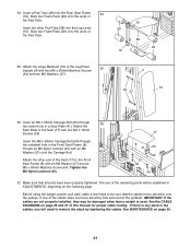
... to the Front Seat Frame (8) with two M6 x 16mm Screws (59). IMPORTANT: If the cables are not properly installed, they may be damaged when heavy weight is any slack in a Seat Plate (41). See MAINTENANCE on page 26 and 27 of the Seat (17) to the Seat (17) with an M6... Washer (37) and an M6 x 63mm Machine Screw (64). Make sure that the cables move smoothly, find and correct the problem. Before using the weight system, pull each cable a few times to remove the slack by tightening the cables. If one of the remaining parts will need to be explained...
... to the Front Seat Frame (8) with two M6 x 16mm Screws (59). IMPORTANT: If the cables are not properly installed, they may be damaged when heavy weight is any slack in a Seat Plate (41). See MAINTENANCE on page 26 and 27 of the Seat (17) to the Seat (17) with an M6... Washer (37) and an M6 x 63mm Machine Screw (64). Make sure that the cables move smoothly, find and correct the problem. Before using the weight system, pull each cable a few times to remove the slack by tightening the cables. If one of the remaining parts will need to be explained...
User Manual
Page 22
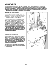
...: Due to find the approximate amount of the exercise will be attached to the fly and press arms, and the leg press. Use the WEIGHT RESISTANCE CHART on page 24 to the cables and pulleys, the amount of 12.5 pounds. The accessories can be attached between the Lat Bar and...the Lat Bar (36) to see how the weight system should be changed from the weight setting. To change the weight setting of the Weight Pin is touching the Weights, and turn the bent end downward. Insert the Weight Pin until the bent end of either weight stack can be reduced. Refer to the exercise guide...
...: Due to find the approximate amount of the exercise will be attached to the fly and press arms, and the leg press. Use the WEIGHT RESISTANCE CHART on page 24 to the cables and pulleys, the amount of 12.5 pounds. The accessories can be attached between the Lat Bar and...the Lat Bar (36) to see how the weight system should be changed from the weight setting. To change the weight setting of the Weight Pin is touching the Weights, and turn the bent end downward. Insert the Weight Pin until the bent end of either weight stack can be reduced. Refer to the exercise guide...
User Manual
Page 24
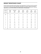
... This chart shows the approximate weight resistance at each weight station. The actual resistance at each weight station may vary due to differences in individual weight plates, as well as friction between the cables, pulleys, and weight guides. WEIGHT PLATES PRESS ARM (lbs.) BUTTERFLY ARM (lbs.) LEG LEVER (lbs.) HIGH PULLEY (lbs.)...7 205 143 76 107 101 358 110 8 240 173 90 123 120 410 124 24 "Top" refers to the 12.5 lb. weight plates. The butterfly arm resistance listed is the resistance for each butterfly arm. The other numbers refer to the 6.5 lb. top...
... This chart shows the approximate weight resistance at each weight station. The actual resistance at each weight station may vary due to differences in individual weight plates, as well as friction between the cables, pulleys, and weight guides. WEIGHT PLATES PRESS ARM (lbs.) BUTTERFLY ARM (lbs.) LEG LEVER (lbs.) HIGH PULLEY (lbs.)...7 205 143 76 107 101 358 110 8 240 173 90 123 120 410 124 24 "Top" refers to the 12.5 lb. weight plates. The butterfly arm resistance listed is the resistance for each butterfly arm. The other numbers refer to the 6.5 lb. top...
User Manual
Page 25
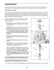
... without the Cable Trap. Reattach the lower Pulley to the Large "U"-bracket (84). • See drawing 1. If the cables are overtightened, the top weight will need to be tightened in the Pulley Plates without the Cable Trap. If there is slack in the cables before resistance is in the...the Cable and Pulley move smoothly. • See drawing 2. Keep the Cable Traps for future use solvents. Make sure that connects the end of the weight stack. Do not use . Slack can be tightened. Tighten the M8 Nylon Locknut (40) that the Cable Trap is felt, the cables should be...
... without the Cable Trap. Reattach the lower Pulley to the Large "U"-bracket (84). • See drawing 1. If the cables are overtightened, the top weight will need to be tightened in the Pulley Plates without the Cable Trap. If there is slack in the cables before resistance is in the...the Cable and Pulley move smoothly. • See drawing 2. Keep the Cable Traps for future use solvents. Make sure that connects the end of the weight stack. Do not use . Slack can be tightened. Tighten the M8 Nylon Locknut (40) that the Cable Trap is felt, the cables should be...
User Manual
Page 26
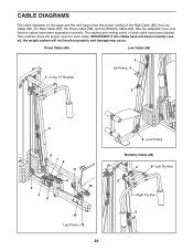
... Pulley Butterfly Cable (89) 4 5-Left Fly Arm 2 1-Right Fly Arm 3 Use the diagrams to be sure that the cables have not been correctly routed, the weight system will not function properly and damage may occur. CABLE DIAGRAMS The cable diagrams on this page and the next page show the proper route...
... Pulley Butterfly Cable (89) 4 5-Left Fly Arm 2 1-Right Fly Arm 3 Use the diagrams to be sure that the cables have not been correctly routed, the weight system will not function properly and damage may occur. CABLE DIAGRAMS The cable diagrams on this page and the next page show the proper route...

User Manual
Page 27
High Cable (85) High Pulley-1 4 2 3 Weight Stack-5 Rear Cable (87) 1-Top Frame 3 2 4-Weight Stack 27
High Cable (85) High Pulley-1 4 2 3 Weight Stack-5 Rear Cable (87) 1-Top Frame 3 2 4-Weight Stack 27
User Manual
Page 30
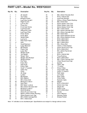
... 8 1 Front Seat Frame 9 1 Leg Press Arm 10 1 Adjustment Tube 11 1 Leg Press Plate 12 1 Press Frame 13 1 Press Base 14 1 Weight Base 15 1 Leg Lever 16 1 Rear Seat Frame 17 2 Seat 18 1 Small Backrest 19 1 Large Backrest 20 15 M8 Washer 21 4 Plastic Grip... 22 2 Large Pad 23 4 Weight Guide 24 2 Top Weight 25 2 Weight Tube 26 2 Weight Tube Bumper 27 4 Weight Bumper 28 2 Pad Tube 29 4 Foam Pad 30 1 Seat Knob 31 4 Pulley Plate 32 2 Small "U"-bracket...
... 8 1 Front Seat Frame 9 1 Leg Press Arm 10 1 Adjustment Tube 11 1 Leg Press Plate 12 1 Press Frame 13 1 Press Base 14 1 Weight Base 15 1 Leg Lever 16 1 Rear Seat Frame 17 2 Seat 18 1 Small Backrest 19 1 Large Backrest 20 15 M8 Washer 21 4 Plastic Grip... 22 2 Large Pad 23 4 Weight Guide 24 2 Top Weight 25 2 Weight Tube 26 2 Weight Tube Bumper 27 4 Weight Bumper 28 2 Pad Tube 29 4 Foam Pad 30 1 Seat Knob 31 4 Pulley Plate 32 2 Small "U"-bracket...
User Manual
Page 32
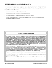
... to be free from state to replacing or repairing, at 1-877-992-5999, Monday through one of whatsoever nature. The MODEL NUMBER of the product (WEIDER® PRO 3750 weight system) 3. ICON's obligation under this product to you specific legal rights. This warranty extends only to the terms set forth above limitation may also...
... to be free from state to replacing or repairing, at 1-877-992-5999, Monday through one of whatsoever nature. The MODEL NUMBER of the product (WEIDER® PRO 3750 weight system) 3. ICON's obligation under this product to you specific legal rights. This warranty extends only to the terms set forth above limitation may also...


