
Uk Manual
Page 1
...: [email protected] CAUTION Read all precautions and instructions in the space above for future reference. Model No. WEEVSY2026.0 Serial No. Serial Number Decal (Under Seat) QUESTIONS? If you have questions, or if there are committed to providing complete customer satisfaction. Save this equipment. USER'S MANUAL Visit our website at www...
...: [email protected] CAUTION Read all precautions and instructions in the space above for future reference. Model No. WEEVSY2026.0 Serial No. Serial Number Decal (Under Seat) QUESTIONS? If you have questions, or if there are committed to providing complete customer satisfaction. Save this equipment. USER'S MANUAL Visit our website at www...
Uk Manual
Page 4
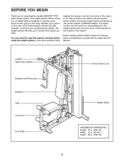
... the front cover of this manual for selecting the versatile WEIDER® PRO 2000 weight system. Before reading further, please review the drawing below and familiarize yourself with the parts that are labeled. Lat Bar High Pulley Station Butterfly Arm/Press Arm Backrest Seat Leg Lever Foot Plate Press Frame Lock Weight Stack ASSEMBLED...
... the front cover of this manual for selecting the versatile WEIDER® PRO 2000 weight system. Before reading further, please review the drawing below and familiarize yourself with the parts that are labeled. Lat Bar High Pulley Station Butterfly Arm/Press Arm Backrest Seat Leg Lever Foot Plate Press Frame Lock Weight Stack ASSEMBLED...
Uk Manual
Page 8
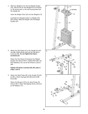
Lubricate the indicated holes in steps 2 and 5. 4 62 70 63 3 69 10 70 68 6. Attach the Seat Frame (8) to the Upright (3) with grease. Attach the Top Frame (4) to the Seat Frame (8) with 5 two M8 x 68mm Bolts (63) and two M8 Nylon Locknuts (69). Slide the Weight onto the Weight Guides (10). 10 Lubricate...
Lubricate the indicated holes in steps 2 and 5. 4 62 70 63 3 69 10 70 68 6. Attach the Seat Frame (8) to the Upright (3) with grease. Attach the Top Frame (4) to the Seat Frame (8) with 5 two M8 x 68mm Bolts (63) and two M8 Nylon Locknuts (69). Slide the Weight onto the Weight Guides (10). 10 Lubricate...

Uk Manual
Page 9
the Leg Lever must pivot easily. 8 64 70 4 Grease 70 68 9. Repeat this step with the bracket on the Seat Frame. Grease the M10 x 57mm Bolt Set (81) and attach the Leg Lever to the Left Arm (7) with two M6 x 58mm Screws (65) and two ...M6 Washers (73). Attach an Arm Pad (20) to the Seat Frame (8) with the Bolt, two M10 Washers (70), and an M10 Nylon Locknut (68). Make sure that the barrel of the Bolt Set is inserted...
the Leg Lever must pivot easily. 8 64 70 4 Grease 70 68 9. Repeat this step with the bracket on the Seat Frame. Grease the M10 x 57mm Bolt Set (81) and attach the Leg Lever to the Left Arm (7) with two M6 x 58mm Screws (65) and two ...M6 Washers (73). Attach an Arm Pad (20) to the Seat Frame (8) with the Bolt, two M10 Washers (70), and an M10 Nylon Locknut (68). Make sure that the barrel of the Bolt Set is inserted...

Uk Manual
Page 15
Slide a Pad Tube (45) through the hole in the Leg Lever (9). Slide two Foam Pads (21) onto the ends of the Pad Tube. Attach the Backrest (18) to the Seat Frame (8) with four M6 x 16mm Screws (40). 31 19 Wide End 8 40 40 32. Repeat this step with two M6 x 63mm Screws (67) and two M6 Washers (73). 30 18 Wide End 67 73 3 73 67 31. Then, press two Pad Caps (22) onto the Pad Tube. SEAT ASSEMBLY 30. Attach the Seat (19), oriented as shown, to the Upright (3) with the other Pad Tube (45) and the Seat Frame (8). 32 22 21 9 45 8 21 45 22 15
Slide a Pad Tube (45) through the hole in the Leg Lever (9). Slide two Foam Pads (21) onto the ends of the Pad Tube. Attach the Backrest (18) to the Seat Frame (8) with four M6 x 16mm Screws (40). 31 19 Wide End 8 40 40 32. Repeat this step with two M6 x 63mm Screws (67) and two M6 Washers (73). 30 18 Wide End 67 73 3 73 67 31. Then, press two Pad Caps (22) onto the Pad Tube. SEAT ASSEMBLY 30. Attach the Seat (19), oriented as shown, to the Upright (3) with the other Pad Tube (45) and the Seat Frame (8). 32 22 21 9 45 8 21 45 22 15
Uk Manual
Page 17
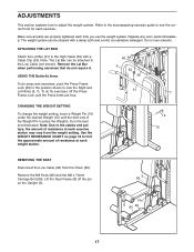
... end downward. Note: Due to the cables and pulleys, the amount of resistance at each exercise station may vary from the Chain (83). Lift the Seat Frame (8) off the pin on page 18 to the High Cable (50) with a damp cloth and a mild, non-abrasive detergent. Refer to the accompanying exercise... weight setting, insert a Weight Pin (16) under the desired Weight (15) until the bent end of resistance at each weight station. 16 15 REMOVING THE SEAT Disconnect the Low Cable (48) from the weight setting. ADJUSTMENTS This section explains how to the Low Cable (not shown).
... end downward. Note: Due to the cables and pulleys, the amount of resistance at each exercise station may vary from the Chain (83). Lift the Seat Frame (8) off the pin on page 18 to the High Cable (50) with a damp cloth and a mild, non-abrasive detergent. Refer to the accompanying exercise... weight setting, insert a Weight Pin (16) under the desired Weight (15) until the bent end of resistance at each weight station. 16 15 REMOVING THE SEAT Disconnect the Low Cable (48) from the weight setting. ADJUSTMENTS This section explains how to the Low Cable (not shown).
Uk Manual
Page 21
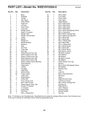
...Qty. Description Key No. Description 1 1 Base 2 1 Stabilizer 3 1 Upright 4 1 Top Frame 5 1 Press Frame 6 1 Right Arm 7 1 Left Arm 8 1 Seat Frame 9 1 Leg Lever 10 2 Weight Guide 11 1 Small "U"-bracket 12 1 Weight Tube 13 1 Weight Tube Bumper 14 2 Guard 15 11 Weight 16 1 Weight Pin... 17 2 Weight Bumper 18 1 Backrest 19 1 Seat 20 2 Arm Pad 21 4 Foam Pad 22 4 Pad Cap 23 2 25mm Round Inner Cap 24 8 45mm Square Inner Cap 25 3 25mm ...
...Qty. Description Key No. Description 1 1 Base 2 1 Stabilizer 3 1 Upright 4 1 Top Frame 5 1 Press Frame 6 1 Right Arm 7 1 Left Arm 8 1 Seat Frame 9 1 Leg Lever 10 2 Weight Guide 11 1 Small "U"-bracket 12 1 Weight Tube 13 1 Weight Tube Bumper 14 2 Guard 15 11 Weight 16 1 Weight Pin... 17 2 Weight Bumper 18 1 Backrest 19 1 Seat 20 2 Arm Pad 21 4 Foam Pad 22 4 Pad Cap 23 2 25mm Round Inner Cap 24 8 45mm Square Inner Cap 25 3 25mm ...

