
English Manual
Page 1
WESY75742 Serial No. www.proform.com Wspraitceethaebosveeriafol rnfuumtubnreeerwreinfpetrhreoendcuec. Visit our website at Model No. Visit our website at www.reebokhomefitness.com new products, prizes, fitness tips, and much more! ts, prizes, fitness tips, and much more ! The trained technicians on our customer hot line will guarantee completeVsisatiits-our website at www.weiderplatinum.com Visit our website at Serial Number Decwawl (uwn.dheer saelatht)rider.com new products, prizes, QUESTIOfitNneSss?tips, and much more ! Visit our website at www.weslo.com new ...
WESY75742 Serial No. www.proform.com Wspraitceethaebosveeriafol rnfuumtubnreeerwreinfpetrhreoendcuec. Visit our website at Model No. Visit our website at www.reebokhomefitness.com new products, prizes, fitness tips, and much more! ts, prizes, fitness tips, and much more ! The trained technicians on our customer hot line will guarantee completeVsisatiits-our website at www.weiderplatinum.com Visit our website at Serial Number Decwawl (uwn.dheer saelatht)rider.com new products, prizes, QUESTIOfitNneSss?tips, and much more ! Visit our website at www.weslo.com new ...
English Manual
Page 2
WEIDER is a registered trademark of this manual. TABLE OF CONTENTS WARNING DECAL PLACEMENT 3 IMPORTANT PRECAUTIONS 4 BEFORE YOU BEGIN 5 ASSEMBLY 6 UPPER CABLE ADJUSTMENT 12 ADJUSTMENTS 13 CONSOLE OPERATION 16 CABLE DIAGRAM 18 TROUBLESHOOTING 19 EXERCISE GUIDELINES 20 ORDERING REPLACEMENT PARTS Back Cover LIMITED WARRANTY Back Cover Note: A PART IDENTIFICATION CHART and a PART LIST/EXPLODED DRAWING are attached in the center of ICON IP, Inc. 2 Remove the PART IDENTIFICATION CHART and PART LIST/EXPLODED DRAWING before beginning assembly.
WEIDER is a registered trademark of this manual. TABLE OF CONTENTS WARNING DECAL PLACEMENT 3 IMPORTANT PRECAUTIONS 4 BEFORE YOU BEGIN 5 ASSEMBLY 6 UPPER CABLE ADJUSTMENT 12 ADJUSTMENTS 13 CONSOLE OPERATION 16 CABLE DIAGRAM 18 TROUBLESHOOTING 19 EXERCISE GUIDELINES 20 ORDERING REPLACEMENT PARTS Back Cover LIMITED WARRANTY Back Cover Note: A PART IDENTIFICATION CHART and a PART LIST/EXPLODED DRAWING are attached in the center of ICON IP, Inc. 2 Remove the PART IDENTIFICATION CHART and PART LIST/EXPLODED DRAWING before beginning assembly.
English Manual
Page 3
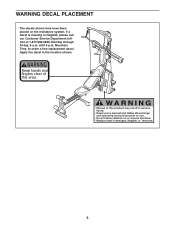
Mountain Time, to order a free replacement decal. until 6 p.m. If a decal is missing or illegible, please call our Customer Service Department tollfree at 1-877-992-5999, Monday through Friday, 6 a.m. Apply the decal in the location shown. WARNING DECAL PLACEMENT The decals shown here have been placed on the resistance system. Keep hands and fingers clear of this area. 149331 3
Mountain Time, to order a free replacement decal. until 6 p.m. If a decal is missing or illegible, please call our Customer Service Department tollfree at 1-877-992-5999, Monday through Friday, 6 a.m. Apply the decal in the location shown. WARNING DECAL PLACEMENT The decals shown here have been placed on the resistance system. Keep hands and fingers clear of this area. 149331 3
English Manual
Page 4
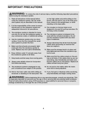
Keep children under 12 and pets away from the high cables when performing an exercise that does not require it. 14. Always disconnect the lat bar from the resistance system at all parts are exercising, stop immediately and begin cooling down. The resistance system is designed to ensure that all times. 7. Use the resistance system only on the cables while the resist- Replace any commercial, rental, or institutional setting. 4. Always wear athletic shoes for personal injury or property damage sustained by or through the use the resistance system with pre-...
Keep children under 12 and pets away from the high cables when performing an exercise that does not require it. 14. Always disconnect the lat bar from the resistance system at all parts are exercising, stop immediately and begin cooling down. The resistance system is designed to ensure that all times. 7. Use the resistance system only on the cables while the resist- Replace any commercial, rental, or institutional setting. 4. Always wear athletic shoes for personal injury or property damage sustained by or through the use the resistance system with pre-...
English Manual
Page 5
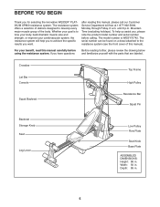
... WESY75742. The serial number can be found on a decal attached to develop every major muscle group of this manual). If you for selecting the innovative WEIDER® PLATINUM XP800 resistance system. To help you to tone your body, build dramatic muscle size and strength, or improve your benefit, read this manual, please...
... WESY75742. The serial number can be found on a decal attached to develop every major muscle group of this manual). If you for selecting the innovative WEIDER® PLATINUM XP800 resistance system. To help you to tone your body, build dramatic muscle size and strength, or improve your benefit, read this manual, please...
English Manual
Page 6
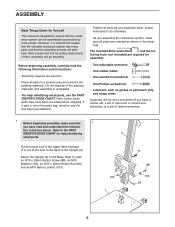
Note: Some small parts may have read the following information and instructions: • Assembly requires two persons. • Place all parts in the back of the hole in a cleared area and remove the packing materials. Before beginning assembly, make sure all parts as grease or petroleum jelly, and soapy water. Pull the lower end of the Upper Wire Harness (71) out of the Upright (2). Before beginning assembly, carefully read and understand the informa- lowing tools (not included) are oriented as shown in the box above. If a part is completed. • For help ...
Note: Some small parts may have read the following information and instructions: • Assembly requires two persons. • Place all parts in the back of the hole in a cleared area and remove the packing materials. Before beginning assembly, make sure all parts as grease or petroleum jelly, and soapy water. Pull the lower end of the Upper Wire Harness (71) out of the Upright (2). Before beginning assembly, carefully read and understand the informa- lowing tools (not included) are oriented as shown in the box above. If a part is completed. • For help ...
English Manual
Page 7
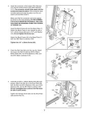
2. IF THE CONNECTOR IS NOT INSERTED PROPERLY, THE CONSOLE MAY BE DAMAGED WHEN THE POWER IS TURNED ON. Attach the Mech Frame (6) to the Rail (4) with two M10 x 64mm Button Bolts (80), four M10 Washers (106), and two M10 Nylon Locknuts (103). 6 12 85 117 71 103 2 1 103 Black Wire 117 Red 71 Wire 103 106 4 Holes on this side 106 49 80 5 4. Do not overtighten the Locknut; Insert the connector of the Upper Wire Harness (71) into the Row Plate (28) and the Rail (4). 103 106 30 29 28 4 30 106 89 Lubricate 7 Attach 3 the Leg to the Base Plate (1) with a 1/2" x ...
2. IF THE CONNECTOR IS NOT INSERTED PROPERLY, THE CONSOLE MAY BE DAMAGED WHEN THE POWER IS TURNED ON. Attach the Mech Frame (6) to the Rail (4) with two M10 x 64mm Button Bolts (80), four M10 Washers (106), and two M10 Nylon Locknuts (103). 6 12 85 117 71 103 2 1 103 Black Wire 117 Red 71 Wire 103 106 4 Holes on this side 106 49 80 5 4. Do not overtighten the Locknut; Insert the connector of the Upper Wire Harness (71) into the Row Plate (28) and the Rail (4). 103 106 30 29 28 4 30 106 89 Lubricate 7 Attach 3 the Leg to the Base Plate (1) with a 1/2" x ...
English Manual
Page 8
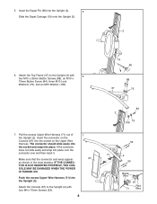
5. The connector should slide easily into the socket and snap into place, turn the connector over and then insert it. Pull the excess Upper Wire Harness (71) out of the Upright (2). If the connector does not slide easily and snap into place. IF THE CONNECTOR IS NOT INSERTED PROPERLY, THE CONSOLE MAY BE DAMAGED WHEN THE POWER IS TURNED ON. 7 67 Push the excess Upper Wire Harness (71) into the socket on the Upper Wire Harness. Make sure that the connector and wires appear as shown in the inset drawing. Attach the Top Frame (37) to the Upright (2) with 6 two M10 x 25mm Button ...
5. The connector should slide easily into the socket and snap into place, turn the connector over and then insert it. Pull the excess Upper Wire Harness (71) out of the Upright (2). If the connector does not slide easily and snap into place. IF THE CONNECTOR IS NOT INSERTED PROPERLY, THE CONSOLE MAY BE DAMAGED WHEN THE POWER IS TURNED ON. 7 67 Push the excess Upper Wire Harness (71) into the socket on the Upper Wire Harness. Make sure that the connector and wires appear as shown in the inset drawing. Attach the Top Frame (37) to the Upright (2) with 6 two M10 x 25mm Button ...
English Manual
Page 9
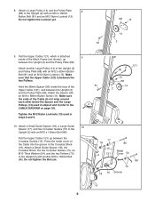
Press the metal cover on page 18). Do not tighten the Bolt yet. 121 11 90 13 68 81 14 2 17 18 86 15 Metal 2 121 Cover 54 86 70 18 16 Groove 9 Make sure that the Upper Cable (121) is attached 9 inside the loop of the Mech Frame (not shown), up between the Upright (2) and the Pulley Plate (68). Tighten the M12 Nylon Locknuts (13) used in steps 8 and 9 (refer to the Upright (2) with an M12 x 62mm Button Bolt (81) and an M12 Nylon Locknut (13). Hold the 38mm Spacer (90) inside of the Upper Cable (121), and between the Crossbar Guides (15). Do ...
Press the metal cover on page 18). Do not tighten the Bolt yet. 121 11 90 13 68 81 14 2 17 18 86 15 Metal 2 121 Cover 54 86 70 18 16 Groove 9 Make sure that the Upper Cable (121) is attached 9 inside the loop of the Mech Frame (not shown), up between the Upright (2) and the Pulley Plate (68). Tighten the M12 Nylon Locknuts (13) used in steps 8 and 9 (refer to the Upright (2) with an M12 x 62mm Button Bolt (81) and an M12 Nylon Locknut (13). Hold the 38mm Spacer (90) inside of the Upper Cable (121), and between the Crossbar Guides (15). Do ...
English Manual
Page 10
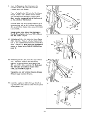
Insert the Resistance Bar (9) between the Crossbar Guides (15), and center it on page 18. Make sure the hexagonal hole in the CABLE DIAGRAM on page 18. 11 15 70 103 9 54 10 80 114 12 13 10 87 14 121 13. Repeat on the outside of the Resistance Bar (9). Make sure that the Cable is on the other Pulley Bracket (10) with a 14 Leg Station Pin (60). Make sure that the Cable is routed as shown in the Screw is routed as shown in step 10. 12. Slide a Cotter Pin (113) onto the Leg Station Pin. 121 87 13 114 10 14 5 56 113 60 10 Attach a Tether (70) to a Pulley Bracket (...
Insert the Resistance Bar (9) between the Crossbar Guides (15), and center it on page 18. Make sure the hexagonal hole in the CABLE DIAGRAM on page 18. 11 15 70 103 9 54 10 80 114 12 13 10 87 14 121 13. Repeat on the outside of the Resistance Bar (9). Make sure that the Cable is on the other Pulley Bracket (10) with a 14 Leg Station Pin (60). Make sure that the Cable is routed as shown in the Screw is routed as shown in step 10. 12. Slide a Cotter Pin (113) onto the Leg Station Pin. 121 87 13 114 10 14 5 56 113 60 10 Attach a Tether (70) to a Pulley Bracket (...

English Manual
Page 11
Rod Slot 44 32 44 17. Slide two Large Foam Pads (52) onto the Pad Tube. The use of the remaining parts will be explained in the inset drawing. Before using the resistance system, turn on the console and change the resistance setting as shown in ADJUSTMENTS, beginning on the following page. 18. Slide a Pad Tube (50) into the 16 slot in CONSOLE OPERATION on the Backrest Frame (32) into the Leg (5). Hold the Backrest Frame vertically over the Seat Carriage and 32 slide the rod into the slot, as described in the Seat Carriage (44). 15. Insert the rod on page 16....
Rod Slot 44 32 44 17. Slide two Large Foam Pads (52) onto the Pad Tube. The use of the remaining parts will be explained in the inset drawing. Before using the resistance system, turn on the console and change the resistance setting as shown in ADJUSTMENTS, beginning on the following page. 18. Slide a Pad Tube (50) into the 16 slot in CONSOLE OPERATION on the Backrest Frame (32) into the Leg (5). Hold the Backrest Frame vertically over the Seat Carriage and 32 slide the rod into the slot, as described in the Seat Carriage (44). 15. Insert the rod on page 16....
English Manual
Page 12
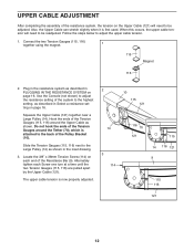
When this occurs, the upper cable tension will need to be adjusted. Use the Console (not shown) to adjust the resistance setting of the system to the highest setting, as described in PLUGGING IN THE RESISTANCE SYSTEM on page 16. Plug in the resistance system as described in Select a resistance setting on page 16. Squeeze the Upper Cable (121) together near a Large Pulley (14). Locate the 3/8" x 38mm Tension Screw (114) on the Upper Cable (121) will need to be readjusted. Do not hook the ends of the Tension Gauges around the Upper Cable as shown in the inset drawing...
When this occurs, the upper cable tension will need to be adjusted. Use the Console (not shown) to adjust the resistance setting of the system to the highest setting, as described in PLUGGING IN THE RESISTANCE SYSTEM on page 16. Plug in the resistance system as described in Select a resistance setting on page 16. Squeeze the Upper Cable (121) together near a Large Pulley (14). Locate the 3/8" x 38mm Tension Screw (114) on the Upper Cable (121) will need to be readjusted. Do not hook the ends of the Tension Gauges around the Upper Cable as shown in the inset drawing...
English Manual
Page 13
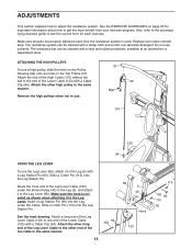
Attach the other end of the Lower Cable (120) with a Cable Clip (94). Remove the high pulleys when not in the same manner. Slide a Cotter Pin (113) onto the Leg Station Pin. Make sure the hook is used. Attach the other long end of the Leg Lever Cable to the other high pulley in use. 37 39 Ball 101 120 94 USING THE LEG LEVER To use the Leg Lever (56), attach it to the Leg (5) with a damp cloth and a mild, non-abrasive detergent. The resistance system can be cleaned with a Leg Station Pin (60). ATTACHING THE HIGH PULLEYS To use solvents. Slide a Cotter Pin (...
Attach the other end of the Lower Cable (120) with a Cable Clip (94). Remove the high pulleys when not in the same manner. Slide a Cotter Pin (113) onto the Leg Station Pin. Make sure the hook is used. Attach the other long end of the Leg Lever Cable to the other high pulley in use. 37 39 Ball 101 120 94 USING THE LEG LEVER To use the Leg Lever (56), attach it to the Leg (5) with a damp cloth and a mild, non-abrasive detergent. The resistance system can be cleaned with a Leg Station Pin (60). ATTACHING THE HIGH PULLEYS To use solvents. Slide a Cotter Pin (...
English Manual
Page 14
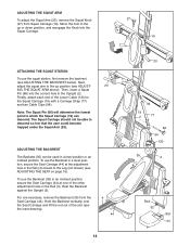
Then, insert a Squat Pin (66) into the Squat Carriage. 27 19 ATTACHING THE SQUAT STATION To use the squat station, first remove the backrest (see ADJUSTING THE SEAT on page 15). Rest the Backrest against the Upright (2). Finally, attach each end of the Lower Cable (120) to the up position (see the inset drawing). 4 44 14 20 94 19 2 77 66 94 120 35 2 Rod 32 Slot 44 Hold the Backrest vertically over the Seat Carriage and lift the rod out of the other adjustment holes in the Rail (4). ADJUSTING THE BACKREST The Backrest (35) can descend. Next, adjust the squat ...
Then, insert a Squat Pin (66) into the Squat Carriage. 27 19 ATTACHING THE SQUAT STATION To use the squat station, first remove the backrest (see ADJUSTING THE SEAT on page 15). Rest the Backrest against the Upright (2). Finally, attach each end of the Lower Cable (120) to the up position (see the inset drawing). 4 44 14 20 94 19 2 77 66 94 120 35 2 Rod 32 Slot 44 Hold the Backrest vertically over the Seat Carriage and lift the rod out of the other adjustment holes in the Rail (4). ADJUSTING THE BACKREST The Backrest (35) can descend. Next, adjust the squat ...
English Manual
Page 15
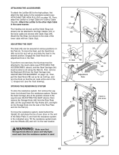
ATTACHING THE ACCESSORIES To attach the Lat Bar (82) to the high pulleys, first attach the high pulley to the other High Cable in the same manner. Attach the Hip Strap (not shown) to the ends of the Row Plate and into the Rail (4). ADJUSTING THE SEAT The Seat (45) can be attached to the desired position. First, remove the Backrest (35) from the resistance system. Tilt the resistance system back onto the Wheels (65) and roll it will go and slide the Seat to the High Cables (101) or the lower cable (not shown) with Cable Clips (94). Attach the Lat Bar to the resistance system (...
ATTACHING THE ACCESSORIES To attach the Lat Bar (82) to the high pulleys, first attach the high pulley to the other High Cable in the same manner. Attach the Hip Strap (not shown) to the ends of the Row Plate and into the Rail (4). ADJUSTING THE SEAT The Seat (45) can be attached to the desired position. First, remove the Backrest (35) from the resistance system. Tilt the resistance system back onto the Wheels (65) and roll it will go and slide the Seat to the High Cables (101) or the lower cable (not shown) with Cable Clips (94). Attach the Lat Bar to the resistance system (...
English Manual
Page 16
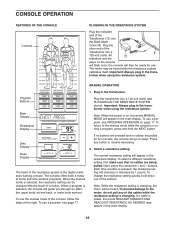
the console will appear in the main display. 16 MANUAL OPERATION Program Buttons Main Display Resistance Display 1. Plug the transformer into the Back Mech Cover (8). To use a program, see PROGRAM OPERATION on the console will appear in the transformer when using the resistance system. Sets Display Reps Display The heart of the resistance system is on, the words MANUAL MODE will then be heard while the resistance system calibrates itself. Press any of the cables while the resistance setting is changing. buttons. The motor may appear in the main display. ...
the console will appear in the main display. 16 MANUAL OPERATION Program Buttons Main Display Resistance Display 1. Plug the transformer into the Back Mech Cover (8). To use a program, see PROGRAM OPERATION on the console will appear in the transformer when using the resistance system. Sets Display Reps Display The heart of the resistance system is on, the words MANUAL MODE will then be heard while the resistance system calibrates itself. Press any of the cables while the resistance setting is changing. buttons. The motor may appear in the main display. ...
English Manual
Page 17
As the resistance bar begins to 340 pounds. 3. Enter the numbers of resistance will increase rapidly, up to bend, the amount of sets and repetitions that you complete during your workout. 4. Note: If you do not enter the numbers of sets and repetitions for the exercise. Unplug the transformer. Note: To see the correct form for an exercise. Adjust the resistance setting and the numbers of sets and repetitions that you plan to do, the console will count down the repetitions and sets you plan to complete for the cardio row exercise, see PLUGGING IN THE RESISTANCE SYSTEM on...
As the resistance bar begins to 340 pounds. 3. Enter the numbers of resistance will increase rapidly, up to bend, the amount of sets and repetitions that you complete during your workout. 4. Note: If you do not enter the numbers of sets and repetitions for the exercise. Unplug the transformer. Note: To see the correct form for an exercise. Adjust the resistance setting and the numbers of sets and repetitions that you plan to do, the console will count down the repetitions and sets you plan to complete for the cardio row exercise, see PLUGGING IN THE RESISTANCE SYSTEM on...
English Manual
Page 18
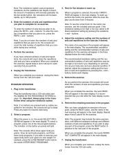
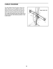
If the cable has not been correctly routed, the resistance system will not function properly and damage may occur. CABLE DIAGRAM The cable diagram shows the proper routing of the cable do not 5 wrap around each other between positions 1 and 2, and 6 and 7. Make sure that the cable has been assembled correctly. Upper Cable (121) 4 6 2 7 1 3 18 The numbers show the correct route for the cable. Use the diagram to make sure that the ends of the Upper Cable (121).
If the cable has not been correctly routed, the resistance system will not function properly and damage may occur. CABLE DIAGRAM The cable diagram shows the proper routing of the cable do not 5 wrap around each other between positions 1 and 2, and 6 and 7. Make sure that the cable has been assembled correctly. Upper Cable (121) 4 6 2 7 1 3 18 The numbers show the correct route for the cable. Use the diagram to make sure that the ends of the Upper Cable (121).
English Manual
Page 19
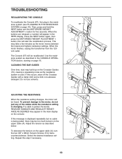
This may build up on the console. When the motor finishes, unplug the transformer from the 120volt outlet. CLEANING THE BAR GUIDES Over time, dust may take a few minutes as the resistance system is pulled, the words RELEASE HANDLES AND READJUST RESISTANCE AS DESIRED may be too much tension on page 16). To prevent damage to the motor, do not pull any of the cables while the resistance setting is being pulled, there may appear in the REPS display. If this will be heard. Press the NEXT button again, then press the MOTORIZED WEIGHT ADJUSTMENT + button; The Console (67) will ...
This may build up on the console. When the motor finishes, unplug the transformer from the 120volt outlet. CLEANING THE BAR GUIDES Over time, dust may take a few minutes as the resistance system is pulled, the words RELEASE HANDLES AND READJUST RESISTANCE AS DESIRED may be too much tension on page 16). To prevent damage to the motor, do not pull any of the cables while the resistance setting is being pulled, there may appear in the REPS display. If this will be heard. Press the NEXT button again, then press the MOTORIZED WEIGHT ADJUSTMENT + button; The Console (67) will ...
English Manual
Page 20
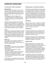
You can complete 3 sets of 12 repetitions without difficulty, increase the amount of resistance. A "set" is a series of repetitions.) The proper amount of resistance for 1 minute after each set should last about half as long as one full day each week to give balance and variety to your workouts, vary the exercises from both strength training and aerobic exercise for you feeling exhausted. Rest for each repetition should be sensitive to your body's signals. The combination of strength training and aerobic exercise will leave you , stick with it during the return stroke. ...
You can complete 3 sets of 12 repetitions without difficulty, increase the amount of resistance. A "set" is a series of repetitions.) The proper amount of resistance for 1 minute after each set should last about half as long as one full day each week to give balance and variety to your workouts, vary the exercises from both strength training and aerobic exercise for you feeling exhausted. Rest for each repetition should be sensitive to your body's signals. The combination of strength training and aerobic exercise will leave you , stick with it during the return stroke. ...