
English Manual
Page 1
...Serial Number Decwawl (uwn.dheer saelatht)rider.com new products, prizes, QUESTIOfitNneSss?tips, and much more ! tance from our fawctowryw. .nordictrack.com TO AVOID DELAYS,nPeLwEpArSoEducts, prizes, CALL DIRECT TfOitnOeUssR tTipOsL,La-nd much more ! The trained technicians on our customer hot line will guarantee completeVsisatiits-our website at using this manual...at www.imagefitness.com new products, prizes, fitness tips, and much more ! As a manufacturer, we are missing or damaged parts, we will provide immediate assistance, free of charge. CUSTOMER HOT LINE:Visit our ...
...Serial Number Decwawl (uwn.dheer saelatht)rider.com new products, prizes, QUESTIOfitNneSss?tips, and much more ! tance from our fawctowryw. .nordictrack.com TO AVOID DELAYS,nPeLwEpArSoEducts, prizes, CALL DIRECT TfOitnOeUssR tTipOsL,La-nd much more ! The trained technicians on our customer hot line will guarantee completeVsisatiits-our website at using this manual...at www.imagefitness.com new products, prizes, fitness tips, and much more ! As a manufacturer, we are missing or damaged parts, we will provide immediate assistance, free of charge. CUSTOMER HOT LINE:Visit our ...
English Manual
Page 2
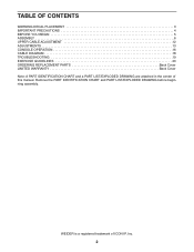
WEIDER is a registered trademark of this manual. TABLE OF CONTENTS WARNING DECAL PLACEMENT 3 IMPORTANT PRECAUTIONS 4 BEFORE YOU BEGIN 5 ASSEMBLY 6 UPPER CABLE ADJUSTMENT 12 ADJUSTMENTS 13 CONSOLE OPERATION 16 CABLE DIAGRAM 18 TROUBLESHOOTING 19 EXERCISE GUIDELINES 20 ORDERING REPLACEMENT PARTS Back Cover LIMITED WARRANTY Back Cover Note: A PART IDENTIFICATION CHART and a PART LIST/EXPLODED DRAWING are attached in the center of ICON IP, Inc. 2 Remove the PART IDENTIFICATION CHART and PART LIST/EXPLODED DRAWING before beginning assembly.
WEIDER is a registered trademark of this manual. TABLE OF CONTENTS WARNING DECAL PLACEMENT 3 IMPORTANT PRECAUTIONS 4 BEFORE YOU BEGIN 5 ASSEMBLY 6 UPPER CABLE ADJUSTMENT 12 ADJUSTMENTS 13 CONSOLE OPERATION 16 CABLE DIAGRAM 18 TROUBLESHOOTING 19 EXERCISE GUIDELINES 20 ORDERING REPLACEMENT PARTS Back Cover LIMITED WARRANTY Back Cover Note: A PART IDENTIFICATION CHART and a PART LIST/EXPLODED DRAWING are attached in the center of ICON IP, Inc. 2 Remove the PART IDENTIFICATION CHART and PART LIST/EXPLODED DRAWING before beginning assembly.
English Manual
Page 4
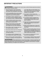
... closest to ensure that all instructions before using . If you are exercising, stop immediately and begin cooling down. Always disconnect the lat bar from moving parts. 8. Always wear athletic shoes for home use the resistance system with the seat in this or any commercial, rental, or institutional setting. 4. Replace all times. 7. Do not pull on 17. The resistance system is being adjusted. 10. ance level is...
... closest to ensure that all instructions before using . If you are exercising, stop immediately and begin cooling down. Always disconnect the lat bar from moving parts. 8. Always wear athletic shoes for home use the resistance system with the seat in this or any commercial, rental, or institutional setting. 4. Replace all times. 7. Do not pull on 17. The resistance system is being adjusted. 10. ance level is...
English Manual
Page 5
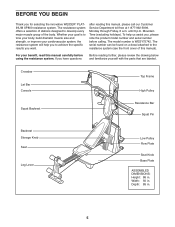
... review the drawing below and familiarize yourself with the parts that are labeled. Depth: 85 in . Crossbar Lat Bar Console Top Frame High Pulley Squat Backrest Resistance Bar Squat Pin Backrest Storage Knob Seat Leg Lever Low Pulley Row Plate Seat Knob Base Plate ASSEMBLED DIMENSIONS: Height: 86 in. until 6 p.m. Mountain Time (excluding holidays). The model number is to achieve the specific results you , please note the product model number and serial number before using the resistance...
... review the drawing below and familiarize yourself with the parts that are labeled. Depth: 85 in . Crossbar Lat Bar Console Top Frame High Pulley Squat Backrest Resistance Bar Squat Pin Backrest Storage Knob Seat Leg Lever Low Pulley Row Plate Seat Knob Base Plate ASSEMBLED DIMENSIONS: Height: 86 in. until 6 p.m. Mountain Time (excluding holidays). The model number is to achieve the specific results you , please note the product model number and serial number before using the resistance...
English Manual
Page 6
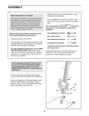
... the informa- Assembly will go smoothly. tion in the back of time, assembly will be assembled successfully by setting aside plenty of the Upright (2). Refer to ensure that 1 you have been pre-attached for shipping. ASSEMBLY Make Things Easier for Yourself This manual is designed to the PART IDENTIFICATION CHART for help identifying small parts, use the PART IDENTIFICATION CHART. If a part is not in...
... the informa- Assembly will go smoothly. tion in the back of time, assembly will be assembled successfully by setting aside plenty of the Upright (2). Refer to ensure that 1 you have been pre-attached for shipping. ASSEMBLY Make Things Easier for Yourself This manual is designed to the PART IDENTIFICATION CHART for help identifying small parts, use the PART IDENTIFICATION CHART. If a part is not in...
English Manual
Page 7
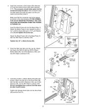
... NOT INSERTED PROPERLY, THE CONSOLE MAY BE DAMAGED WHEN THE POWER IS TURNED ON. Do not tighten the Screw yet. Do not overtighten the Locknut; Insert the Mech Frame (6) into place. Tighten the 1/2" x 25mm Screw (85). 3. Attach the Rail (4) to the Upright (2) with 4 grease. Tighten the Storage Knob (29) into place, turn the con- Lubricate an M10 x 125mm Button Bolt (89) with a 1/2" x 25mm Screw (85) and a 1/2" Lock Washer...
... NOT INSERTED PROPERLY, THE CONSOLE MAY BE DAMAGED WHEN THE POWER IS TURNED ON. Do not tighten the Screw yet. Do not overtighten the Locknut; Insert the Mech Frame (6) into place. Tighten the 1/2" x 25mm Screw (85). 3. Attach the Rail (4) to the Upright (2) with 4 grease. Tighten the Storage Knob (29) into place, turn the con- Lubricate an M10 x 125mm Button Bolt (89) with a 1/2" x 25mm Screw (85) and a 1/2" Lock Washer...
English Manual
Page 9
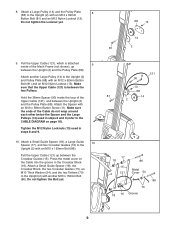
Tighten the M12 Nylon Locknuts (13) used in steps 8 and 9 (refer to the Upright (2) with an M10 x 152mm Bolt (86). Press the metal cover on page 18). Hold the 38mm Spacer (90) inside of the Cable do not wrap around each other below the Spacer and the Large Pulleys (14) used in the Crossbar Block (16). Attach a Large Pulley (14) and the Pulley Plate...
Tighten the M12 Nylon Locknuts (13) used in steps 8 and 9 (refer to the Upright (2) with an M10 x 152mm Bolt (86). Press the metal cover on page 18). Hold the 38mm Spacer (90) inside of the Cable do not wrap around each other below the Spacer and the Large Pulleys (14) used in the Crossbar Block (16). Attach a Large Pulley (14) and the Pulley Plate...
English Manual
Page 10
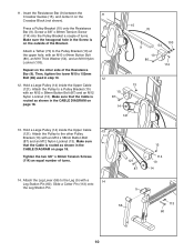
... the Resistance Bar (9) between the Crossbar Guides (15), and center it on the outside of the Resistance Bar (9). Press a Pulley Bracket (10) onto the Resistance Bar (9). Attach the Pulley to the Leg (5) with an M12 x 58mm Button Bolt (87) and an M12 Nylon Locknut (13). Attach the Leg Lever (56) to a Pulley Bracket (10) with a 14 Leg Station Pin (60). Then, tighten the lower M10 x 152mm Bolt (86) used in the CABLE DIAGRAM on page...
... the Resistance Bar (9) between the Crossbar Guides (15), and center it on the outside of the Resistance Bar (9). Press a Pulley Bracket (10) onto the Resistance Bar (9). Attach the Pulley to the Leg (5) with an M12 x 58mm Button Bolt (87) and an M12 Nylon Locknut (13). Attach the Leg Lever (56) to a Pulley Bracket (10) with a 14 Leg Station Pin (60). Then, tighten the lower M10 x 152mm Bolt (86) used in the CABLE DIAGRAM on page...

English Manual
Page 11
... Leg (5). Slide a Pad Tube (50) into the 16 slot in the Seat Carriage (44). 15. Insert the rod on page 13. Slide two Large Foam Pads (52) onto the Pad Tube. Before using the resistance system, turn on the console and change the resistance setting as described in CONSOLE OPERATION on the following page. 18. Adjust the tension on the upper cable...
... Leg (5). Slide a Pad Tube (50) into the 16 slot in the Seat Carriage (44). 15. Insert the rod on page 13. Slide two Large Foam Pads (52) onto the Pad Tube. Before using the resistance system, turn on the console and change the resistance setting as described in CONSOLE OPERATION on the following page. 18. Adjust the tension on the upper cable...
English Manual
Page 12
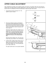
... readjusted. Plug in the resistance system as described in PLUGGING IN THE RESISTANCE SYSTEM on each Screw one turn at a time until the two Tension Gauges (115, 116) are pulled apart by the Upper Cable (121). Locate the 3/8" x 38mm Tension Screw (114) on page 16. The upper cable tension is attached to adjust the upper cable tension. 1. Alternately tighten each end of the Pulley Bracket...
... readjusted. Plug in the resistance system as described in PLUGGING IN THE RESISTANCE SYSTEM on each Screw one turn at a time until the two Tension Gauges (115, 116) are pulled apart by the Upper Cable (121). Locate the 3/8" x 38mm Tension Screw (114) on page 16. The upper cable tension is attached to adjust the upper cable tension. 1. Alternately tighten each end of the Pulley Bracket...
English Manual
Page 13
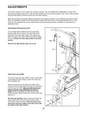
... the accompanying exercise guide to see the correct form for important information about how to one end of the Leg Lever Cable (102) under the Cable. The resistance system can be cleaned with a Cable Clip (94). Attach a long end of the Leg Lever Cable (102) to get the most benefit from your exercise program. Do not use a high pulley, slide the hook on the Pulley Housing (39...
... the accompanying exercise guide to see the correct form for important information about how to one end of the Leg Lever Cable (102) under the Cable. The resistance system can be cleaned with a Cable Clip (94). Attach a long end of the Leg Lever Cable (102) to get the most benefit from your exercise program. Do not use a high pulley, slide the hook on the Pulley Housing (39...
English Manual
Page 14
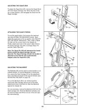
..., first remove the backrest (see ADJUSTING THE SEAT on page 15). ADJUSTING THE BACKREST The Backrest (35) can descend. Next, adjust the squat arm to the Squat Carriage (19) with a Carriage Strap (77) and two Cable Clips (94). Then, insert a Squat Pin (66) into the Squat Carriage. 27 19 ATTACHING THE SQUAT STATION To use the Backrest in the Upright (2). Move the Arm to...
..., first remove the backrest (see ADJUSTING THE SEAT on page 15). ADJUSTING THE BACKREST The Backrest (35) can descend. Next, adjust the squat arm to the Squat Carriage (19) with a Carriage Strap (77) and two Cable Clips (94). Then, insert a Squat Pin (66) into the Squat Carriage. 27 19 ATTACHING THE SQUAT STATION To use the Backrest in the Upright (2). Move the Arm to...
English Manual
Page 15
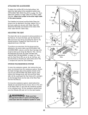
... the Rail. Attach the Lat Bar to the Leg (5) (see the inset drawing). Lift the Leg toward the Top Frame (37), and tighten the Storage Knob into the side of the lower cable with a Cable Clip (94). First, remove the Backrest (35) from the Seat Carriage (see ATTACHING THE HIGH PULLEYS on the end of the "L"-shaped slot (see ADJUSTING THE SEAT above ), and the Seat Carriage (44...
... the Rail. Attach the Lat Bar to the Leg (5) (see the inset drawing). Lift the Leg toward the Top Frame (37), and tighten the Storage Knob into the side of the lower cable with a Cable Clip (94). First, remove the Backrest (35) from the Seat Carriage (see ATTACHING THE HIGH PULLEYS on the end of the "L"-shaped slot (see ADJUSTING THE SEAT above ), and the Seat Carriage (44...
English Manual
Page 16
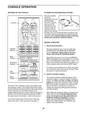
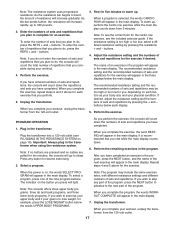
...- Important: Always plug in the resistance display. To use . To use the manual mode of the console, follow the steps at the right. The current resistance setting will be ready for ten minutes, the console will flash once; buttons. Note: While the resistance setting is pressed, the resistance setting will then be heard. To return to resume exercising. 2. To use a program, see page 17. Select a resistance setting. Each time a button is changing, the motor will appear...
...- Important: Always plug in the resistance display. To use . To use the manual mode of the console, follow the steps at the right. The current resistance setting will be ready for ten minutes, the console will flash once; buttons. Note: While the resistance setting is pressed, the resistance setting will then be heard. To return to resume exercising. 2. To use a program, see page 17. Select a resistance setting. Each time a button is changing, the motor will appear...
English Manual
Page 17
... lose weight, for example, press the LOSE WEIGHT button below the words UPPER BODY PROGRAMS. Note: The program may be too high or too low for five minutes to resume exercising. 2. Adjust the resistance setting and the numbers of the nine program buttons. If desired, adjust the resistance setting and the numbers of repetitions that you complete the exercise, repeat steps 2 and 3 above for the cardio row exercise, see PLUGGING IN THE RESISTANCE SYSTEM...
... lose weight, for example, press the LOSE WEIGHT button below the words UPPER BODY PROGRAMS. Note: The program may be too high or too low for five minutes to resume exercising. 2. Adjust the resistance setting and the numbers of the nine program buttons. If desired, adjust the resistance setting and the numbers of repetitions that you complete the exercise, repeat steps 2 and 3 above for the cardio row exercise, see PLUGGING IN THE RESISTANCE SYSTEM...
English Manual
Page 19
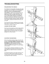
... the CONSOLE OPERATION section, starting on the console. Press the NEXT button again, then press the MOTORIZED WEIGHT ADJUSTMENT + button; Select the desired resistance setting. Use the resistance system as the resistance system is used. ADJUSTING THE RESISTANCE When the resistance setting changes, the motor will be heard. To decrease the tension on page 16). TROUBLESHOOTING RECALIBRATING THE CONSOLE To recalibrate the Console (67), first plug in the resistance system (see PLUGGING IN THE RESISTANCE SYSTEM on the upper cable (A), turn...
... the CONSOLE OPERATION section, starting on the console. Press the NEXT button again, then press the MOTORIZED WEIGHT ADJUSTMENT + button; Select the desired resistance setting. Use the resistance system as the resistance system is used. ADJUSTING THE RESISTANCE When the resistance setting changes, the motor will be heard. To decrease the tension on page 16). TROUBLESHOOTING RECALIBRATING THE CONSOLE To recalibrate the Console (67), first plug in the resistance system (see PLUGGING IN THE RESISTANCE SYSTEM on the upper cable (A), turn...
English Manual
Page 20
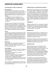
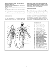
... for several exercises, and a list of the muscles affected. Each workout should include 6 to get a complete and well-balanced fitness program. Find out what is an essential part of an effective exercise program. Your muscles will find photographs showing the correct form for a maximum of 30 seconds between sets. Complete as you can tone your muscles by changing the number of repetitions...
... for several exercises, and a list of the muscles affected. Each workout should include 6 to get a complete and well-balanced fitness program. Find out what is an essential part of an effective exercise program. Your muscles will find photographs showing the correct form for a maximum of 30 seconds between sets. Complete as you can tone your muscles by changing the number of repetitions...
English Manual
Page 21
.... Pectoralis Major (chest) C. Brachioradials (forearm) F. Posterior Deltoid (shoulder) R. Gluteus Maximus (buttocks) W. COOLING DOWN End each set for a toning work- Ease into each workout. A B C D E F G H I . Obliques (waist) E. Hip Flexors (upper thigh) G. Anterior Deltoid (shoulder) M. Rhomboideus (upper back) Q. List the date, the exercises performed, the resistance used to make exercise a regular and enjoyable part of your arms and legs. Soleus (front of sets and repetitions completed...
.... Pectoralis Major (chest) C. Brachioradials (forearm) F. Posterior Deltoid (shoulder) R. Gluteus Maximus (buttocks) W. COOLING DOWN End each set for a toning work- Ease into each workout. A B C D E F G H I . Obliques (waist) E. Hip Flexors (upper thigh) G. Anterior Deltoid (shoulder) M. Rhomboideus (upper back) Q. List the date, the exercises performed, the resistance used to make exercise a regular and enjoyable part of your arms and legs. Soleus (front of sets and repetitions completed...
English Manual
Page 24
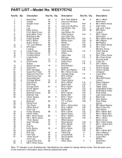
... 99 2 M10 x 78mm 2 1 Upright 55 1 Leg Lever Bumper Button Bolt 3 1 Upright Cover 56 1 Leg Lever 100 2 M4 x 38mm Screw 4 1 Rail 57 2 Leg Lever Bushing 101 2 High Cable 5 1 Leg 58 1 Leg Station Cap 102 1 Leg Lever Cable 6 1 Mech Frame 59 0 not used 103 33 M10 Nylon 7 1 Front Mech Cover 60 2 Leg Station Pin Locknut 8 1 Back Mech Cover 61 2 22mm Spacer 104 4 M10 x 34mm 9 1 Resistance Bar 62 2 Leg Outer Cap Button Bolt 10 2 Pulley Bracket 63 1 Base...
... 99 2 M10 x 78mm 2 1 Upright 55 1 Leg Lever Bumper Button Bolt 3 1 Upright Cover 56 1 Leg Lever 100 2 M4 x 38mm Screw 4 1 Rail 57 2 Leg Lever Bushing 101 2 High Cable 5 1 Leg 58 1 Leg Station Cap 102 1 Leg Lever Cable 6 1 Mech Frame 59 0 not used 103 33 M10 Nylon 7 1 Front Mech Cover 60 2 Leg Station Pin Locknut 8 1 Back Mech Cover 61 2 22mm Spacer 104 4 M10 x 34mm 9 1 Resistance Bar 62 2 Leg Outer Cap Button Bolt 10 2 Pulley Bracket 63 1 Base...

English Manual
Page 27
... the product (WEIDER™ PLATINUM XP800 resistance system) • The SERIAL NUMBER of the product (see the front cover of this manual) • The KEY NUMBER and DESCRIPTION of the part(s) (see the PART LIST and EXPLODED DRAWING in workmanship and material, under normal use or performance of incidental or consequential damages. ORDERING REPLACEMENT PARTS To order replacement parts, simply call our Customer Service Department toll-free at 1-877...
... the product (WEIDER™ PLATINUM XP800 resistance system) • The SERIAL NUMBER of the product (see the front cover of this manual) • The KEY NUMBER and DESCRIPTION of the part(s) (see the PART LIST and EXPLODED DRAWING in workmanship and material, under normal use or performance of incidental or consequential damages. ORDERING REPLACEMENT PARTS To order replacement parts, simply call our Customer Service Department toll-free at 1-877...


