

English Manual
Page 1
... Serial No. Write the serial number in the space above for reference. 0 OO O INE DER 0 II Serial Number Decal QUESTIONS? TO AVOID UNNECESSARY DELAYS, PLEASE CALL DIRECT TO OUR TOLL-FREE CUSTOMER HOT LINE. CUSTOMER HOT LINE: 1-800-225-0653 Mon.-Fri., 6 a.m.-6 p.m. As a manufacturer, we will provide immediate assistance, free of charge to providing complete customer satisfaction. Model No. The trained...
... Serial No. Write the serial number in the space above for reference. 0 OO O INE DER 0 II Serial Number Decal QUESTIONS? TO AVOID UNNECESSARY DELAYS, PLEASE CALL DIRECT TO OUR TOLL-FREE CUSTOMER HOT LINE. CUSTOMER HOT LINE: 1-800-225-0653 Mon.-Fri., 6 a.m.-6 p.m. As a manufacturer, we will provide immediate assistance, free of charge to providing complete customer satisfaction. Model No. The trained...

English Manual
Page 2
... apply to you . TABLE OF CONTENTS LIMITED WARRANTY IMPORTANT PRECAUTIONS BEFORE YOU BEGIN ASSEMBLY ADJUSTMENT TROUBLE-SHOOTING AND MAINTENANCE CABLE DIAGRAM PART LIST EXPLODED DRAWING ORDERING REPLACEMENT PARTS 2 3 4 5 17 19 20 22 23 Back Cover Note: a PART IDENTIFICATION CHART is attached to the center of this product to be free from defects in workmanship and material, under this warranty is limited to replacing or repairing, at ICON's option, the product at one...
... apply to you . TABLE OF CONTENTS LIMITED WARRANTY IMPORTANT PRECAUTIONS BEFORE YOU BEGIN ASSEMBLY ADJUSTMENT TROUBLE-SHOOTING AND MAINTENANCE CABLE DIAGRAM PART LIST EXPLODED DRAWING ORDERING REPLACEMENT PARTS 2 3 4 5 17 19 20 22 23 Back Cover Note: a PART IDENTIFICATION CHART is attached to the center of this product to be free from defects in workmanship and material, under this warranty is limited to replacing or repairing, at ICON's option, the product at one...

English Manual
Page 4
... of this manual carefully before calling. The serial number can be found on a decal attached to the WEIDER® 8512 (see the front cover of the body. The WEIDER® 8512 offers a selection of weight stations designed to achieve the specific results you , please note the product model number and serial number before Before reading further, please review the drawing using the WEIDER® 8512 Home Gym System. Service Department toll-free at 1-800...
... of this manual carefully before calling. The serial number can be found on a decal attached to the WEIDER® 8512 (see the front cover of the body. The WEIDER® 8512 offers a selection of weight stations designed to achieve the specific results you , please note the product model number and serial number before Before reading further, please review the drawing using the WEIDER® 8512 Home Gym System. Service Department toll-free at 1-800...

English Manual
Page 5
... been pre-attached. • As you assemble the home gym system, be needed. Slide the indicated end of the home gym system in a cleared area and remove the packing materials; Slide the Rear Upright (56) onto the Carriage Bolts. do otherwise. Hand tighten a 5/16" Nylon Locknut (3) onto each end of the Base (4). Press a 2" Square Outer Cap (51) onto each Carriage Bolt. ASSEMBLY Before beginning assembly, carefully...
... been pre-attached. • As you assemble the home gym system, be needed. Slide the indicated end of the home gym system in a cleared area and remove the packing materials; Slide the Rear Upright (56) onto the Carriage Bolts. do otherwise. Hand tighten a 5/16" Nylon Locknut (3) onto each end of the Base (4). Press a 2" Square Outer Cap (51) onto each Carriage Bolt. ASSEMBLY Before beginning assembly, carefully...

English Manual
Page 6
... Bolt. Tighten all of the crossbar on the Base (4) as shown. Be sure that all Nylon Locknuts used in the Base (4). Set two Weight Bumpers (19) onto the bracket on the Top Frame. Press a 1 3/4" Square Inner Cap (44) into the top of the Top Frame (55). Attach the Top Frame (55) to the Front Upright (42) and the Rear Upright...
... Bolt. Tighten all of the crossbar on the Base (4) as shown. Be sure that all Nylon Locknuts used in the Base (4). Set two Weight Bumpers (19) onto the bracket on the Top Frame. Press a 1 3/4" Square Inner Cap (44) into the top of the Top Frame (55). Attach the Top Frame (55) to the Front Upright (42) and the Rear Upright...

English Manual
Page 7
..." x 6" 6 Bolt (60), two 1/2" x 3/4" Spacers (61), and a 5/16" Nylon Locknut (3). Set the Top Weight onto the stack of the holes in the upper Weight. Pin Holes 62 Lubricate 63 64 25 Attach the upper ends of Weights (25). Be sure that the holes in 76 the Weight Guides are resting in the pin grooves in the Top Weight (76). The Plastic Bushings should fit...
..." x 6" 6 Bolt (60), two 1/2" x 3/4" Spacers (61), and a 5/16" Nylon Locknut (3). Set the Top Weight onto the stack of the holes in the upper Weight. Pin Holes 62 Lubricate 63 64 25 Attach the upper ends of Weights (25). Be sure that the holes in 76 the Weight Guides are resting in the pin grooves in the Top Weight (76). The Plastic Bushings should fit...

English Manual
Page 8
Attach the Press Arm to one side of the Right Arm is very important for easy part identification. refer to step 9 to confuse the Right Arm with the Left Arm (47); Attach the Left Arm (47) in the same manner. 46 22 44 49 46 9. Note: The "V"-Pulleys (6), Long Cable Traps (50), 3/8" x 2 1/2" Bolts (7), and 3/8" Nylon Locknuts (21) are pre-attached. These have been shown disassembled for...
Attach the Press Arm to one side of the Right Arm is very important for easy part identification. refer to step 9 to confuse the Right Arm with the Left Arm (47); Attach the Left Arm (47) in the same manner. 46 22 44 49 46 9. Note: The "V"-Pulleys (6), Long Cable Traps (50), 3/8" x 2 1/2" Bolts (7), and 3/8" Nylon Locknuts (21) are pre-attached. These have been shown disassembled for...

English Manual
Page 9
... nuts securing the pulleys. Tighten the 3/8" x 3 3/4" Bolt (71) and the 3/8" Nylon Locknut (not shown). 13. Be sure that the Cable is posi- During steps 11 through 25, refer to hold the Cable in place. Before beginning this manual to hold the Cable in place. 14. Locate the Long Cable (23). Route the Long Cable around the indicated 3 1/2" Pulley (15) 12 attached to turn freely. 11...
... nuts securing the pulleys. Tighten the 3/8" x 3 3/4" Bolt (71) and the 3/8" Nylon Locknut (not shown). 13. Be sure that the Cable is posi- During steps 11 through 25, refer to hold the Cable in place. Before beginning this manual to hold the Cable in place. 14. Locate the Long Cable (23). Route the Long Cable around the indicated 3 1/2" Pulley (15) 12 attached to turn freely. 11...

English Manual
Page 10
... in this drawing is shown disassembled for easy part identification. Route the Long Cable (23) around the "V"- 15 Pulley (6) on the Top Frame (55). bled. 15. Tighten the 3/8" x 2 1/2" Bolt (7) and the 3/8" Nylon Locknut (not shown). 50 7 6 \\ 48 23 16. Attach a 3 1/2" Pulley (15) and a Cable Trap (66) to the Pulley Bracket (20). Be sure that the Cable and Pulley move freely. 16 68 66 20...
... in this drawing is shown disassembled for easy part identification. Route the Long Cable (23) around the "V"- 15 Pulley (6) on the Top Frame (55). bled. 15. Tighten the 3/8" x 2 1/2" Bolt (7) and the 3/8" Nylon Locknut (not shown). 50 7 6 \\ 48 23 16. Attach a 3 1/2" Pulley (15) and a Cable Trap (66) to the Pulley Bracket (20). Be sure that the Cable and Pulley move freely. 16 68 66 20...

English Manual
Page 11
... Q the ball is between the Pulley and the Press Frame (17). Remove the 3/8" Nylon Locknut (21), the Spacer, and the Pulley from the 3/8" x 3 3/4" Bolt (71). Locate the Short Cable (58). Do not tighten the 3/8" Nylon Locknut (21) yet. Route the 20 LLI Short Cable (58) under the 3 1/2" Pulley (15) attached to 19 complete the assembly of the 3 1/2" Pulley (15) for part identification. 19. The 5/8" x 9/16...
... Q the ball is between the Pulley and the Press Frame (17). Remove the 3/8" Nylon Locknut (21), the Spacer, and the Pulley from the 3/8" x 3 3/4" Bolt (71). Locate the Short Cable (58). Do not tighten the 3/8" Nylon Locknut (21) yet. Route the 20 LLI Short Cable (58) under the 3 1/2" Pulley (15) attached to 19 complete the assembly of the 3 1/2" Pulley (15) for part identification. 19. The 5/8" x 9/16...

English Manual
Page 12
... the Front Upright (42). Tighten the 3/8" Nylon Locknut (21) and the 3/8" x 3 1/2" Bolt (not shown). 42 15 71 66 58 Inset shows view from other side 58 15 66 21 17 23. Be sure that the Cable is routed around the 3 1/2" Pulley (15) attached to hold the Cable in place and that the Cable Trap (66) is turned to the lower hole...
... the Front Upright (42). Tighten the 3/8" Nylon Locknut (21) and the 3/8" x 3 1/2" Bolt (not shown). 42 15 71 66 58 Inset shows view from other side 58 15 66 21 17 23. Be sure that the Cable is routed around the 3 1/2" Pulley (15) attached to hold the Cable in place and that the Cable Trap (66) is turned to the lower hole...

English Manual
Page 13
...tighten the Nylon Locknut. tl 10 57 ---- 58 25 Attach the Small "U"-Bracket (67) to the Small "U"Bracket (67) with a 1/4" Nylon Locknut (2) and a 1/4" Flat Washer (10). It should be threaded onto the end of the Cable only a couple of turns, as shown in the inset drawing. 0 57 58 25. Attach the Long Cable (23) to the Weight... Tube (63) with a 1/4" Nylon Lock- 24. Attach the end of turns, as shown in the inset drawing. ...
...tighten the Nylon Locknut. tl 10 57 ---- 58 25 Attach the Small "U"-Bracket (67) to the Small "U"Bracket (67) with a 1/4" Nylon Locknut (2) and a 1/4" Flat Washer (10). It should be threaded onto the end of the Cable only a couple of turns, as shown in the inset drawing. 0 57 58 25. Attach the Long Cable (23) to the Weight... Tube (63) with a 1/4" Nylon Lock- 24. Attach the end of turns, as shown in the inset drawing. ...
English Manual
Page 14
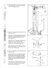
... 24--1 O,--32 18 36 2 Lubricate-33 s 35- 32 3 29 8 Do not overtighten the Nylon Locknut. Attach the 27 Seat Plate to pivot freely. Press a 1 1/2" Square Inner Cap (32) into the Leg Lever (29) from the direction shown. The Leg Lever must be able to the Seat (13) with the 5/16" x 2 1/4" Bolt and a 5/16" Nylon Locknut (3). Tighten a 5/16" Nylon Locknut (3) with...
... 24--1 O,--32 18 36 2 Lubricate-33 s 35- 32 3 29 8 Do not overtighten the Nylon Locknut. Attach the 27 Seat Plate to pivot freely. Press a 1 1/2" Square Inner Cap (32) into the Leg Lever (29) from the direction shown. The Leg Lever must be able to the Seat (13) with the 5/16" x 2 1/4" Bolt and a 5/16" Nylon Locknut (3). Tighten a 5/16" Nylon Locknut (3) with...
English Manual
Page 15
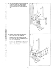
... pin 29 in the Front Upright (42). 29. Press 3/4" Round Inner Caps (34) into the Leg Lever (29). Slide a 5 1/2" Pad (30) onto each end of the Pad Tube. 36 30 I 14 Pin 42 40 36 w •ci) 30. I I 30 34 28 34 29 15 Attach the Seat Frame to the Front Upright with a 5/16" x 2 3/4" Carriage Bolt (14) and the Seat Knob...
... pin 29 in the Front Upright (42). 29. Press 3/4" Round Inner Caps (34) into the Leg Lever (29). Slide a 5 1/2" Pad (30) onto each end of the Pad Tube. 36 30 I 14 Pin 42 40 36 w •ci) 30. I I 30 34 28 34 29 15 Attach the Seat Frame to the Front Upright with a 5/16" x 2 3/4" Carriage Bolt (14) and the Seat Knob...

English Manual
Page 16
... properly tightened. 31 Remove the decals from the decal sheet (not shown) and apply them to the home gym system in ADJUSTMENT, beginning on page 17 of the cables does not move smoothly over the pulleys. Before using the home gym system, pull each cable a few times to be explained in the locations shown below. 31 HIGH PULLEY BUTTERFLY LEG DEVELOPER 0 OO OO 0 BENCH PRESS LOW PULLEY 32...
... properly tightened. 31 Remove the decals from the decal sheet (not shown) and apply them to the home gym system in ADJUSTMENT, beginning on page 17 of the cables does not move smoothly over the pulleys. Before using the home gym system, pull each cable a few times to be explained in the locations shown below. 31 HIGH PULLEY BUTTERFLY LEG DEVELOPER 0 OO OO 0 BENCH PRESS LOW PULLEY 32...

English Manual
Page 17
...) can be adjusted. Use the WEIGHT RESISTANCE CHART on page 18 to 81.5 pounds, in the same manner. The Nylon Strap (39) (not shown) can be changed from the weight setting. Adjust the length of the Weight Pin is performed, the effectiveness of the home gym system can be attached in the correct starting position for the exercise to be attached between the Lat Bar and the Pulley Cable with a Cable Clip (53...
...) can be adjusted. Use the WEIGHT RESISTANCE CHART on page 18 to 81.5 pounds, in the same manner. The Nylon Strap (39) (not shown) can be changed from the weight setting. Adjust the length of the Weight Pin is performed, the effectiveness of the home gym system can be attached in the correct starting position for the exercise to be attached between the Lat Bar and the Pulley Cable with a Cable Clip (53...

English Manual
Page 18
.... ATTACHING AND REMOVING THE SEAT Set the bracket on the Seat Frame (36) onto the indicated pins on the Front Upright (42). For some exercises, the Seat (13) must be sure that the chain is for each station. `Top" refers to the Short Cable (58) with a Cable Clip. 0 52 0 29 53 0 58 35 WEIGHT RESISTANCE CHART This chart shows the approximate weight resistance at each butterfly arm. Weight resistance shown...
.... ATTACHING AND REMOVING THE SEAT Set the bracket on the Seat Frame (36) onto the indicated pins on the Front Upright (42). For some exercises, the Seat (13) must be sure that the chain is for each station. `Top" refers to the Short Cable (58) with a Cable Clip. 0 52 0 29 53 0 58 35 WEIGHT RESISTANCE CHART This chart shows the approximate weight resistance at each butterfly arm. Weight resistance shown...

English Manual
Page 19
...-install it is first used on the back cover of the Short Cable (58) (see ORDERING REPLACEMENT PARTS on the home gym system, can be cleaned using a damp cloth and mild non-abrasive detergent. Make sure that the cables are 0 not too tight, or the Top Weight (76) will be tightened. If the cables need to be 11/ removed from the cables by moving the 3 1/2" Pulley (15) to slip...
...-install it is first used on the back cover of the Short Cable (58) (see ORDERING REPLACEMENT PARTS on the home gym system, can be cleaned using a damp cloth and mild non-abrasive detergent. Make sure that the cables are 0 not too tight, or the Top Weight (76) will be tightened. If the cables need to be 11/ removed from the cables by moving the 3 1/2" Pulley (15) to slip...
English Manual
Page 20
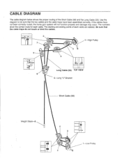
... been correctly routed, the home gym system will not function properly and damage may occur. If the cables have been assembled correctly. The numbers show the correct route for each cable are labeled. Use the diagram to be sure that the cable traps do not touch or bind the cables. 2 7 5 Eg? 3 4 1-High Pulley Long Cable (23) TOP VIEW 6 5-Long "U"-Bracket Short Cable (58) Weight Stack-8 4 3 2 0 1-Low Pulley
... been correctly routed, the home gym system will not function properly and damage may occur. If the cables have been assembled correctly. The numbers show the correct route for each cable are labeled. Use the diagram to be sure that the cable traps do not touch or bind the cables. 2 7 5 Eg? 3 4 1-High Pulley Long Cable (23) TOP VIEW 6 5-Long "U"-Bracket Short Cable (58) Weight Stack-8 4 3 2 0 1-Low Pulley


