

English Manual
Page 2
TABLE OF CONTENTS IMPORTANT PRECAUTIONS 3 BEFORE YOU BEGIN 4 PART IDENTIFICATION CHART 5 ASSEMBLY 7 ADJUSTMENT 18 WEIGHT RESISTANCE CHART 19 TROUBLE-SHOOTING AND MAINTENANCE 20 CABLE DIAGRAM 21 PART LIST 22 EXPLODED DRAWING 23 ORDERING REPLACEMENT PARTS Back Cover LIMITED WARRANTY Back Cover WEIDER is a registered trademark of ICON Health & Fitness, Inc. 2
TABLE OF CONTENTS IMPORTANT PRECAUTIONS 3 BEFORE YOU BEGIN 4 PART IDENTIFICATION CHART 5 ASSEMBLY 7 ADJUSTMENT 18 WEIGHT RESISTANCE CHART 19 TROUBLE-SHOOTING AND MAINTENANCE 20 CABLE DIAGRAM 21 PART LIST 22 EXPLODED DRAWING 23 ORDERING REPLACEMENT PARTS Back Cover LIMITED WARRANTY Back Cover WEIDER is a registered trademark of ICON Health & Fitness, Inc. 2
English Manual
Page 12
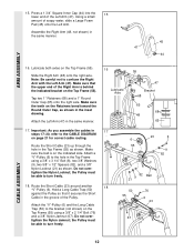
...) in the Top Frame using a 3/8" x 2 1/4" Bolt (76) and a 3/8" Nylon Jamnut (67). Attach a "V"-Pulley (6) to turn freely. 18. Route the Short Cable (23) around another "V"-Pulley (6). ARM ASSEMBLY 15. Using a small amount of the Left Arm (47). Note: Be careful not to the bracket (not shown) on... Pulley so that the upper end of the Pulley. Slide the Right Arm (48) onto the right axle. the Pulley must be able to the CABLE DIAGRAM on the Top Frame (55) using a 3/8" x 3 1/4" Bolt (8), two 3/8" Washers (9), two 5/8" x 1/2" Spacers (82), and a 3/8" Nylon Locknut (21) as shown. Make...
...) in the Top Frame using a 3/8" x 2 1/4" Bolt (76) and a 3/8" Nylon Jamnut (67). Attach a "V"-Pulley (6) to turn freely. 18. Route the Short Cable (23) around another "V"-Pulley (6). ARM ASSEMBLY 15. Using a small amount of the Left Arm (47). Note: Be careful not to the bracket (not shown) on... Pulley so that the upper end of the Pulley. Slide the Right Arm (48) onto the right axle. the Pulley must be able to the CABLE DIAGRAM on the Top Frame (55) using a 3/8" x 3 1/4" Bolt (8), two 3/8" Washers (9), two 5/8" x 1/2" Spacers (82), and a 3/8" Nylon Locknut (21) as shown. Make...
English Manual
Page 17
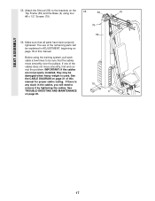
...59) to the brackets on page 21 of the cables does not move smoothly over the pulleys. See the CABLE DIAGRAM on the 35 Top Frame (55) and the Base (4) using the training system, pull each cable a few times to be explained in the cables, you will be sure that all parts have been ...properly tightened. SEAT ASSEMBLY 35. Make sure that the cables move smoothly, find and ...
...59) to the brackets on page 21 of the cables does not move smoothly over the pulleys. See the CABLE DIAGRAM on the 35 Top Frame (55) and the Base (4) using the training system, pull each cable a few times to be explained in the cables, you will be sure that all parts have been ...properly tightened. SEAT ASSEMBLY 35. Make sure that the cables move smoothly, find and ...
English Manual
Page 21
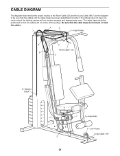
CABLE DIAGRAM The diagram below shows the proper routing of the Short Cable (23) and the Long Cable (69). The cable traps should be sure that the cables and the cable traps have not been cor- rectly routed, the training system will not come off the pulleys. Use the diagram to be positioned so that the cable traps do not touch...
CABLE DIAGRAM The diagram below shows the proper routing of the Short Cable (23) and the Long Cable (69). The cable traps should be sure that the cables and the cable traps have not been cor- rectly routed, the training system will not come off the pulleys. Use the diagram to be positioned so that the cable traps do not touch...


