
Service Manual
Page 5
...) 1000 cd/m2 (Typical) (w/glass filter) Min.300 cd/m Contrast ratio (panel spec) 8000:1 (Typical, dark room) Color Coordinates (typical) White (Panel spec) x=0.300±0.02, y=0.300±0.02 White (w/glass filter) Warm (5400K) Standard (6500K) Cool (9300K): 2. INPUT SOURCE RGB Signal: H: support to 30-80KHz V: support to 60-85Hz Pixel Clock...
...) 1000 cd/m2 (Typical) (w/glass filter) Min.300 cd/m Contrast ratio (panel spec) 8000:1 (Typical, dark room) Color Coordinates (typical) White (Panel spec) x=0.300±0.02, y=0.300±0.02 White (w/glass filter) Warm (5400K) Standard (6500K) Cool (9300K): 2. INPUT SOURCE RGB Signal: H: support to 30-80KHz V: support to 60-85Hz Pixel Clock...

Service Manual
Page 6
...: less than 3W 6. SPEAKER Output 8Ω/10W (max) X2 CONFIDENTIAL - SG-0173 OUTPUT CONNECTORS a. Audio RCA Jack x 2 b. 3.5mm Mini-jack earphone x 1 5. Composite Video signal: H: 15.734KHz V: 60Hz (NTSC) Component signal: YPbPr/YCbCr H: 15.734KHz V: 60Hz (NTSC-480i) H: 31KHz V: 60Hz(NTSC-480p) H: 45KHz V: 60Hz(NTSC-720p) H: 33KHz V: 60Hz(NTSC-1080i) 3. DO NOT COPY...
...: less than 3W 6. SPEAKER Output 8Ω/10W (max) X2 CONFIDENTIAL - SG-0173 OUTPUT CONNECTORS a. Audio RCA Jack x 2 b. 3.5mm Mini-jack earphone x 1 5. Composite Video signal: H: 15.734KHz V: 60Hz (NTSC) Component signal: YPbPr/YCbCr H: 15.734KHz V: 60Hz (NTSC-480i) H: 31KHz V: 60Hz(NTSC-480p) H: 45KHz V: 60Hz(NTSC-720p) H: 33KHz V: 60Hz(NTSC-1080i) 3. DO NOT COPY...

Service Manual
Page 12
... available for PIP and POP modes. (2):For AV1 and AV2, S-Video has priority. If a signal is connected to AV1 S-Video and AV1 Video simultaneously, then S-Video will be the only choice for AV1. The same input priority scheme applies to ...AV1 Video only, then Video will be the only choice for AV1. DO NOT COPY Page 3-5 File No. SG-0173 If a signal is connected to AV2. *** When Speakers off CONFIDENTIAL - AV1 AV2 AV1 AV2 Analog Main \ Sub (S-VIDEO) (S-VIDEO) (VIDEO) (VIDEO) HD1 AV1 (S-VIDEO) x x x x AV2 x (S-VIDEO) x x x AV1...
... available for PIP and POP modes. (2):For AV1 and AV2, S-Video has priority. If a signal is connected to AV1 S-Video and AV1 Video simultaneously, then S-Video will be the only choice for AV1. The same input priority scheme applies to ...AV1 Video only, then Video will be the only choice for AV1. DO NOT COPY Page 3-5 File No. SG-0173 If a signal is connected to AV2. *** When Speakers off CONFIDENTIAL - AV1 AV2 AV1 AV2 Analog Main \ Sub (S-VIDEO) (S-VIDEO) (VIDEO) (VIDEO) HD1 AV1 (S-VIDEO) x x x x AV2 x (S-VIDEO) x x x AV1...

Service Manual
Page 15
Signal level: d. DO NOT COPY Page 5-1 File No. Video bandwidth: g. SG-0173 Connector type: Analog H: 30-80KHz 0.7Vp-p V: 60-85Hz 75Ω H/V separate sync: TTL H/V composite ...
Signal level: d. DO NOT COPY Page 5-1 File No. Video bandwidth: g. SG-0173 Connector type: Analog H: 30-80KHz 0.7Vp-p V: 60-85Hz 75Ω H/V separate sync: TTL H/V composite ...

Service Manual
Page 18
... Response: d. Connector type: 1Vrms (max.) 32Ω 50 mW Earphone mini jack 0.7Vrms 47KΩ 250Hz-20KHz RCA L/R: CONFIDENTIAL - DO NOT COPY Page 5-4 File No. on device) 16 SDA 18 +5V Power 2. Connector type: 2.2 Audio output a. Output 2.1 Earphone a. Signal level: b. Impedance: c. Output: d. Impedance: c. Signal level: b. Pin Signal Assignment 1 TMDS Data2+ 3 TMDS Data25 TMDS Data1...
... Response: d. Connector type: 1Vrms (max.) 32Ω 50 mW Earphone mini jack 0.7Vrms 47KΩ 250Hz-20KHz RCA L/R: CONFIDENTIAL - DO NOT COPY Page 5-4 File No. on device) 16 SDA 18 +5V Power 2. Connector type: 2.2 Audio output a. Output 2.1 Earphone a. Signal level: b. Impedance: c. Output: d. Impedance: c. Signal level: b. Pin Signal Assignment 1 TMDS Data2+ 3 TMDS Data25 TMDS Data1...
Service Manual
Page 26
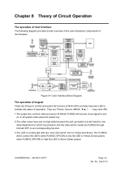
... the user-interactive components of operation. They are "Power, Source, MENU keys and LED. 1.The power key controls video processor FLI8532, FLI8532 will receive a low signal to turn on which key pressed, and the state will transit to low state dependent on or off system while press the power key. 2.The...
... the user-interactive components of operation. They are "Power, Source, MENU keys and LED. 1.The power key controls video processor FLI8532, FLI8532 will receive a low signal to turn on which key pressed, and the state will transit to low state dependent on or off system while press the power key. 2.The...

Service Manual
Page 28
... to anti-alias filters before the Analog to Digital Converters (ADCs). CONFIDENTIAL - Up to 4 different inputs are supported as long as at least 2 of control signals (VS, HS, ODD, etc.), and 4 input clocks. It consists of two 24bit ports (PORTA and PORTB), two sets of these inputs are 8bit CCIR656. These...
... to anti-alias filters before the Analog to Digital Converters (ADCs). CONFIDENTIAL - Up to 4 different inputs are supported as long as at least 2 of control signals (VS, HS, ODD, etc.), and 4 input clocks. It consists of two 24bit ports (PORTA and PORTB), two sets of these inputs are 8bit CCIR656. These...

Service Manual
Page 29
...to other devices. This table below shows how the input DATA buses can be arbitrarily assigned through host registers. PORTA also includes optional signals (DIP_EXT_CLAMP, DIP_EXT_COAST, DIP_CLEAN_HS_OUT) for each group of 8bit inputs. Bits 7 to the digital input port are supported by FLI8532 digital .... The purpose of the input buses for PORTA and PORTB and allows individual Bus Flipping (MSB to LSB) for interfacing to the panel. These signals are not present on PORTB. Figure 8-4 Digital Input DATA bus assignment CONFIDENTIAL - DO NOT COPY Page 8-4 File No. Due to...
...to other devices. This table below shows how the input DATA buses can be arbitrarily assigned through host registers. PORTA also includes optional signals (DIP_EXT_CLAMP, DIP_EXT_COAST, DIP_CLEAN_HS_OUT) for each group of 8bit inputs. Bits 7 to the digital input port are supported by FLI8532 digital .... The purpose of the input buses for PORTA and PORTB and allows individual Bus Flipping (MSB to LSB) for interfacing to the panel. These signals are not present on PORTB. Figure 8-4 Digital Input DATA bus assignment CONFIDENTIAL - DO NOT COPY Page 8-4 File No. Due to...

Service Manual
Page 32
...-Wire Protocol Data Transfer Each transaction on the MSTR_SDA is in the figure below. The number of PIP source input and then output digital video signal to -high transition on MSTR_SDA while MSTR_SCL is held high. In this product, we use FLI8125 to acknowledge receipt of Video Processor FLI8125 FLI8125 is...
...-Wire Protocol Data Transfer Each transaction on the MSTR_SDA is in the figure below. The number of PIP source input and then output digital video signal to -high transition on MSTR_SDA while MSTR_SCL is held high. In this product, we use FLI8125 to acknowledge receipt of Video Processor FLI8125 FLI8125 is...

Service Manual
Page 34
... Analog to the input multiplexer . DO NOT COPY Page 8-9 File No. These integrated features eliminate the need for 16 separate analog signals. SG-0173 Overall application cost is responsible for the AFE and Decoder blocks with connections to Digital Converters (ADCs). CONFIDENTIAL - Figure ...Front End is reduced by providing analog switching capabilities for any devices between the input connector and the AFE pin connection. These signals are re-configurable as different combinations of composite, S-Video, YPrPb and RGB video streams depending upon the end application. The...
... Analog to the input multiplexer . DO NOT COPY Page 8-9 File No. These integrated features eliminate the need for 16 separate analog signals. SG-0173 Overall application cost is responsible for the AFE and Decoder blocks with connections to Digital Converters (ADCs). CONFIDENTIAL - Figure ...Front End is reduced by providing analog switching capabilities for any devices between the input connector and the AFE pin connection. These signals are re-configurable as different combinations of composite, S-Video, YPrPb and RGB video streams depending upon the end application. The...

Service Manual
Page 36
...data to be connected to external DVI receivers, video decoders, etc. Input pixel clock for the 24-bit and 16-bit inputs the following signals are provided: CLK1 - Vertical sync input or SOG input DV/CLAMP - Data valid input indicator NOTE: Unused pins of ... programmable. Inputs to the digital input port are processed as GPIOs to simplify signal detection. The 24-bit Digital Input Port provides control signals to increase the total number of 135MHz. Horizontal sync or composite sync signal VS/SOG - Other RGB input data streams, such as computer inputs...
...data to be connected to external DVI receivers, video decoders, etc. Input pixel clock for the 24-bit and 16-bit inputs the following signals are provided: CLK1 - Vertical sync input or SOG input DV/CLAMP - Data valid input indicator NOTE: Unused pins of ... programmable. Inputs to the digital input port are processed as GPIOs to simplify signal detection. The 24-bit Digital Input Port provides control signals to increase the total number of 135MHz. Horizontal sync or composite sync signal VS/SOG - Other RGB input data streams, such as computer inputs...

Service Manual
Page 37
The selected input data stream is ignored. For a flat panel TV, in a video system since video signals are cropped with respect to fill the entire screen. For all other inputs, the Input Capture Window is referenced with reference to over scanned. ... selected and then expanded to Horizontal and Vertical Sync. SG-0173 Input data streams originating from the input data stream and creating the required synchronization signals required by the data pipeline. CONFIDENTIAL - Figure 8-11 Input Capture Window Input cropping is required in order to the start and end of active...
The selected input data stream is ignored. For a flat panel TV, in a video system since video signals are cropped with respect to fill the entire screen. For all other inputs, the Input Capture Window is referenced with reference to over scanned. ... selected and then expanded to Horizontal and Vertical Sync. SG-0173 Input data streams originating from the input data stream and creating the required synchronization signals required by the data pipeline. CONFIDENTIAL - Figure 8-11 Input Capture Window Input cropping is required in order to the start and end of active...

Service Manual
Page 39
...wide LVDS in the Open LDI standard. to the leading edge of the horizontal sync signal. DO NOT COPY Page 8-14 File No. This mode is programmable to allow the data and control signals to the input frame or field rate. In free-run mode, the display timing ...24-bit RGB pixels format. The integrated LVDS transmitter is used for testing purposes. All display data and timing signals are programmed in line increments relative to a variety of flat panel devices using a 24-bit TTL or LVDS interface. The following display synchronization modes are programmed in single-pixel...
...wide LVDS in the Open LDI standard. to the leading edge of the horizontal sync signal. DO NOT COPY Page 8-14 File No. This mode is programmable to allow the data and control signals to the input frame or field rate. In free-run mode, the display timing ...24-bit RGB pixels format. The integrated LVDS transmitter is used for testing purposes. All display data and timing signals are programmed in line increments relative to a variety of flat panel devices using a 24-bit TTL or LVDS interface. The following display synchronization modes are programmed in single-pixel...

Service Manual
Page 43
... UXGA. DO NOT COPY Page 8-18 File No. Active Port Detection The PanelLink core detects an active TMDS clock and detects an actively toggling DE signal. The microcontroller can monitor the presence of the HDMI input or for monitoring the status of this +5V supply and, if and when necessary, provide...
... UXGA. DO NOT COPY Page 8-18 File No. Active Port Detection The PanelLink core detects an active TMDS clock and detects an actively toggling DE signal. The microcontroller can monitor the presence of the HDMI input or for monitoring the status of this +5V supply and, if and when necessary, provide...
Service Manual
Page 62
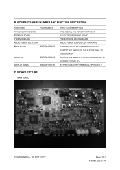
... FUNCTION DESCRIPTION PROVIDE ALL THE POWER FOR TV SET X ELECTRODE DRIVING BOARD Y ELECTRODE DRIVING BOARD AUDIO POWER SUPPLY(+30V OR +24V) CONNECTING TO TRANSFER DISPLY SIGNAL TO PDP SET, AMPLIFIER THE AUDIO SIGNAL TO THE SPEAKER RECEIVE THE REMOTE CONTROLER AND DISPLAY SYSTEM STATUS LED KEYPAD FUNCTION FOR MANUAL OPERATE TV C.
... FUNCTION DESCRIPTION PROVIDE ALL THE POWER FOR TV SET X ELECTRODE DRIVING BOARD Y ELECTRODE DRIVING BOARD AUDIO POWER SUPPLY(+30V OR +24V) CONNECTING TO TRANSFER DISPLY SIGNAL TO PDP SET, AMPLIFIER THE AUDIO SIGNAL TO THE SPEAKER RECEIVE THE REMOTE CONTROLER AND DISPLAY SYSTEM STATUS LED KEYPAD FUNCTION FOR MANUAL OPERATE TV C.
Service Manual
Page 65
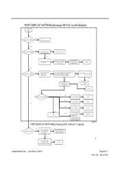
... U13 fail No Yes If power_off Îhigh U2,U5Î ON Check +3.3V_SW ,+5V_SW,+12V_SW (pin 5,6 and pin 7,8) PDP DISPLAY NOTHING(Analog HD1 without Y signal) U2,U5 fail Block 1 No Is picture on /off default) Start No Power LED is lighting? Yes Press Meun or Info. Does scaler detect the...; RLY_ON(high) Check CN3 pin 2Î VS_ON(high) No Check Fuse open? (F2,F3,F4) Yse Check CN1Îpin 1,2,3 = +5V pin 7,8 = +12V No Yes Panel power fail No Fuse fail D10,D11 LED is high? (Display_ON) Remove R87. SG-0174 No U13 fail Yes No Power LED is lighting? Trace...
... U13 fail No Yes If power_off Îhigh U2,U5Î ON Check +3.3V_SW ,+5V_SW,+12V_SW (pin 5,6 and pin 7,8) PDP DISPLAY NOTHING(Analog HD1 without Y signal) U2,U5 fail Block 1 No Is picture on /off default) Start No Power LED is lighting? Yes Press Meun or Info. Does scaler detect the...; RLY_ON(high) Check CN3 pin 2Î VS_ON(high) No Check Fuse open? (F2,F3,F4) Yse Check CN1Îpin 1,2,3 = +5V pin 7,8 = +12V No Yes Panel power fail No Fuse fail D10,D11 LED is high? (Display_ON) Remove R87. SG-0174 No U13 fail Yes No Power LED is lighting? Trace...

Service Manual
Page 66
... Input To U13 circuit Check R204,R201 Yes Use GProbe connect No from main to PC. Does scaler detect the signal? SG-0174 PDP DISPLAY NOTHING(Analog HD1 without Pb signal) BLOCK 1 No Is picture on screen? U13 fail PDP DISPLAY NOTHING(Analog HD1 on PIP mode without... Y signal) BLOCK 1 No Is picture on screen? Check component 1 No (Pr signal) ÎC264 Is there sync? Does scaler detect the signal? Check component 1 No (Pb signal) ÎC259 Is there sync? DO NOT COPY Page10-6 File No.
... Input To U13 circuit Check R204,R201 Yes Use GProbe connect No from main to PC. Does scaler detect the signal? SG-0174 PDP DISPLAY NOTHING(Analog HD1 without Pb signal) BLOCK 1 No Is picture on screen? U13 fail PDP DISPLAY NOTHING(Analog HD1 on PIP mode without... Y signal) BLOCK 1 No Is picture on screen? Check component 1 No (Pr signal) ÎC264 Is there sync? Does scaler detect the signal? Check component 1 No (Pb signal) ÎC259 Is there sync? DO NOT COPY Page10-6 File No.

Service Manual
Page 67
...sync? Trace componect 1 from Input To U10 circuit Check R205,R204 Yes Use GProbe connect No from main to PC. Does scaler detect the signal? Trace componect 1 from Input To U10 circuit Check R200,R198 Yes Use GProbe connect No from main to PC. Yes Check U23 No ... main to PC. DO NOT COPY Page10-7 File No. Does scaler detect the signal? Does scaler detect the signal? No Check component 2 (Y signal) ÎC258,R195 Is there sync? U10 fail PDP DISPLAY NOTHING(Analog HD2 without Pr signal) BLOCK 1 No Is picture on screen? U13 fail Yes Check before U23's...
...sync? Trace componect 1 from Input To U10 circuit Check R205,R204 Yes Use GProbe connect No from main to PC. Does scaler detect the signal? Trace componect 1 from Input To U10 circuit Check R200,R198 Yes Use GProbe connect No from main to PC. Yes Check U23 No ... main to PC. DO NOT COPY Page10-7 File No. Does scaler detect the signal? Does scaler detect the signal? No Check component 2 (Y signal) ÎC258,R195 Is there sync? U10 fail PDP DISPLAY NOTHING(Analog HD2 without Pr signal) BLOCK 1 No Is picture on screen? U13 fail Yes Check before U23's...

Service Manual
Page 68
...) VCC3Îpin 22,23(+5V) Input_switch_selectÎhigh(+5V) U24 fail Use GProbe connect No from main to PC. Does scaler detect the signal? SG-0174 Yes Check U23 No outnputÎpin 34 No InputÎ pin 11 Input clamp voltageÎpin 1(+5V) Output clamp voltage...(+5V) VCC3Îpin 22,23(+5V) Input_switch_selectÎhigh(+5V) U23 fail Use GProbe connect No from main to PC. Does scaler detect the signal? U13 fail Yes Check before U24's circuit No 1.C282,C285(AC coupled) 2.R209 Input source fail 3.R216(75ohm) 4 CONFIDENTIAL - U10 fail Yes Check...
...) VCC3Îpin 22,23(+5V) Input_switch_selectÎhigh(+5V) U24 fail Use GProbe connect No from main to PC. Does scaler detect the signal? SG-0174 Yes Check U23 No outnputÎpin 34 No InputÎ pin 11 Input clamp voltageÎpin 1(+5V) Output clamp voltage...(+5V) VCC3Îpin 22,23(+5V) Input_switch_selectÎhigh(+5V) U23 fail Use GProbe connect No from main to PC. Does scaler detect the signal? U13 fail Yes Check before U24's circuit No 1.C282,C285(AC coupled) 2.R209 Input source fail 3.R216(75ohm) 4 CONFIDENTIAL - U10 fail Yes Check...

Service Manual
Page 69
... 2.R215 Input source fail 3.R218(75ohm) PDP DISPLAY NOTHING(RGB) BLOCK 1 No Is picture on screen? Check component 2 (Pr signal) ÎC284,R210 Is there signal? Yes Check U24 No outnputÎpin 34 No InputÎ pin 11 Input clamp voltageÎpin 1(+5V) Output clamp voltageÎ...CONFIDENTIAL - Check U45 H sync output Î U45 pin4,R181 No V sync output Î U45 pin8,R184 Is there signal? DO NOT COPY Page10-9 File No. Does scaler detect the signal? U10 fail Yes Check before U24's circuit No 1.C289,C290(AC coupled) 2.R211 Input source fail 3.R217(75ohm) PDP ...
... 2.R215 Input source fail 3.R218(75ohm) PDP DISPLAY NOTHING(RGB) BLOCK 1 No Is picture on screen? Check component 2 (Pr signal) ÎC284,R210 Is there signal? Yes Check U24 No outnputÎpin 34 No InputÎ pin 11 Input clamp voltageÎpin 1(+5V) Output clamp voltageÎ...CONFIDENTIAL - Check U45 H sync output Î U45 pin4,R181 No V sync output Î U45 pin8,R184 Is there signal? DO NOT COPY Page10-9 File No. Does scaler detect the signal? U10 fail Yes Check before U24's circuit No 1.C289,C290(AC coupled) 2.R211 Input source fail 3.R217(75ohm) PDP ...

