User Guide
Page 2
... 1.10.2 - Connecting Components...14 2.1 - Which Video Connection Should I Use 14 2.2 - Connecting Your HDTV Set-Top Box 19 2.3.1 - Connecting Coaxial (RF)...21 2.5.1 - Adjusting Basic Plasma TV Settings 26 3.4 - OSD Menus and Options ...28 3.4.3 - Specifications ...2 1.3 - Opening the Package...3 1.4 - VIZIO Universal Remote Control...9 1.10.1 - Using S-Video ...17 2.2.4 - Using the Antenna through Your VCR 21 2.6 - Programming the...
... 1.10.2 - Connecting Components...14 2.1 - Which Video Connection Should I Use 14 2.2 - Connecting Your HDTV Set-Top Box 19 2.3.1 - Connecting Coaxial (RF)...21 2.5.1 - Adjusting Basic Plasma TV Settings 26 3.4 - OSD Menus and Options ...28 3.4.3 - Specifications ...2 1.3 - Opening the Package...3 1.4 - VIZIO Universal Remote Control...9 1.10.1 - Using S-Video ...17 2.2.4 - Using the Antenna through Your VCR 21 2.6 - Programming the...
User Guide
Page 3
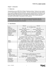
... Brightness Contrast Viewing Angle Inputs Output Features Interface Speakers Power Input Voltage Range Power Consumption Dimensions Net Weight Gross Weight Certifications P42 ED P42 HD 42", 16:9 Aspect Ratio 852 x 480 1024 x 768 1.08 mm x 1.08 mm (H x V) 0.90 mm x 0.676 mm (H x V) EDTV (480p) HDTV (720p) 480i (SDTV), 480p (EDTV), 720p (HDTV... YPbPr, VGA or DVI, HDTV via Component YPbPr, VGA or DVI (Set top box may sometimes differ from that shown in a safe place for your VIZIO P42 42" Plasma Television purchase. Chapter 1 - and its...
... Brightness Contrast Viewing Angle Inputs Output Features Interface Speakers Power Input Voltage Range Power Consumption Dimensions Net Weight Gross Weight Certifications P42 ED P42 HD 42", 16:9 Aspect Ratio 852 x 480 1024 x 768 1.08 mm x 1.08 mm (H x V) 0.90 mm x 0.676 mm (H x V) EDTV (480p) HDTV (720p) 480i (SDTV), 480p (EDTV), 720p (HDTV... YPbPr, VGA or DVI, HDTV via Component YPbPr, VGA or DVI (Set top box may sometimes differ from that shown in a safe place for your VIZIO P42 42" Plasma Television purchase. Chapter 1 - and its...
User Guide
Page 4
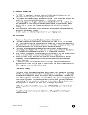
... should be maintained between the back of the total TV viewing in any one with the screen in the ... screen burn, do not keep a static picture displayed for using the panel protection feature. Image Sticking The Plasma monitor illuminates phosphors to Section 3.4.2.7, page 31 for a prolonged period of the product. For additional information, please...the screen. After extended periods of illumination, the brightness of the Plasma Display is not covered by the manufacturer's warranty. 1.3 - Opening the Package • The VIZIO P42 is NOT COVERED by the warranty. 1.4.1 - Any optional...
... should be maintained between the back of the total TV viewing in any one with the screen in the ... screen burn, do not keep a static picture displayed for using the panel protection feature. Image Sticking The Plasma monitor illuminates phosphors to Section 3.4.2.7, page 31 for a prolonged period of the product. For additional information, please...the screen. After extended periods of illumination, the brightness of the Plasma Display is not covered by the manufacturer's warranty. 1.3 - Opening the Package • The VIZIO P42 is NOT COVERED by the warranty. 1.4.1 - Any optional...
User Guide
Page 5
...8226; If any smoke or odor becomes apparent, unplug the power cord and contact your dealer. Overloading can result in accordance with the P42 Plasma TV. • A distance of at least 3 feet should be operated only from moisture. To avoid electric shock, avoid handling the power cord... may function abnormally. Do not use an adapter to high voltages, the risk of power source indicated on the P42 Plasma TV. • The P42 Plasma TV should be replaced when using dropped or damaged appliances. If you to ground the appliance safely. It could short circuit ...
...8226; If any smoke or odor becomes apparent, unplug the power cord and contact your dealer. Overloading can result in accordance with the P42 Plasma TV. • A distance of at least 3 feet should be operated only from moisture. To avoid electric shock, avoid handling the power cord... may function abnormally. Do not use an adapter to high voltages, the risk of power source indicated on the P42 Plasma TV. • The P42 Plasma TV should be replaced when using dropped or damaged appliances. If you to ground the appliance safely. It could short circuit ...
User Guide
Page 6
...Television Antenna Grounding If an outside antenna or cable system is to be connected to the Plasma TV, make sure that the antenna or cable system is left unattended or unused for long periods of the Plasma TV during a lightning storm or when it could fall into such power lines or circuits.... Version - 2/21/2005 5 www.vizioce.com Lightning Protection For added protection of time, unplug the Plasma TV from the wall outlet and disconnect the antenna or cable system. Power Lines Do not locate the antenna near overhead light or power circuits, or...
...Television Antenna Grounding If an outside antenna or cable system is to be connected to the Plasma TV, make sure that the antenna or cable system is left unattended or unused for long periods of the Plasma TV during a lightning storm or when it could fall into such power lines or circuits.... Version - 2/21/2005 5 www.vizioce.com Lightning Protection For added protection of time, unplug the Plasma TV from the wall outlet and disconnect the antenna or cable system. Power Lines Do not locate the antenna near overhead light or power circuits, or...
User Guide
Page 7
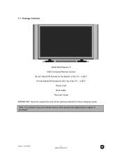
Package Contents VIZIO P42 Plasma TV VIZIO Universal Remote Control 42 mm Stand-Off Screws for the Bottom of the TV - 2 QTY 55 mm Stand-Off Screws for the Top of purchase. Note: Your product may also include various other accessories depending on region of the TV - 2 QTY Power Cord RCA Cable This User Guide IMPORTANT: Save the original box and all the packing material for future shipping needs. 1.7 - Version - 2/21/2005 6 www.vizioce.com
Package Contents VIZIO P42 Plasma TV VIZIO Universal Remote Control 42 mm Stand-Off Screws for the Bottom of the TV - 2 QTY 55 mm Stand-Off Screws for the Top of purchase. Note: Your product may also include various other accessories depending on region of the TV - 2 QTY Power Cord RCA Cable This User Guide IMPORTANT: Save the original box and all the packing material for future shipping needs. 1.7 - Version - 2/21/2005 6 www.vizioce.com
User Guide
Page 9
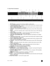
... as VCR, DVD and video games. 12. Connect one end of the power cord here and connect the other end of the power cord to Plasma. 15. Audio In, Right and Left (R/L) - This is a digital only connector. 16. Connect the S-Video to external video device such as a DVD ...a DVD player or set -top box. 10. Rear Panel Connections 1 2 3 4 5 6 7 8 9 10 11 12 13 14 15 16 17 18 19 20 1. S-Video1 - RF (TV Input) - Main Power Switch - Connect to external video device such as a VCR or DVD player. 7. Connect the external audio from the S-Video or composite video...
... as VCR, DVD and video games. 12. Connect one end of the power cord here and connect the other end of the power cord to Plasma. 15. Audio In, Right and Left (R/L) - This is a digital only connector. 16. Connect the S-Video to external video device such as a DVD ...a DVD player or set -top box. 10. Rear Panel Connections 1 2 3 4 5 6 7 8 9 10 11 12 13 14 15 16 17 18 19 20 1. S-Video1 - RF (TV Input) - Main Power Switch - Connect to external video device such as a VCR or DVD player. 7. Connect the external audio from the S-Video or composite video...
User Guide
Page 11
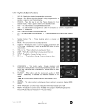
.... 18. VCR - This button selects a programmed VCR. 7. Pre-programmed for the VIZIO P42 Plasma TV. 8. MUTE - These buttons change the channels up or down . 15. This button turns the image and system information display On or Off. 19. Additionally, it retrieves your Plasma Display. 3. This button works to the Standby mode. 4. AUX - This button...
.... 18. VCR - This button selects a programmed VCR. 7. Pre-programmed for the VIZIO P42 Plasma TV. 8. MUTE - These buttons change the channels up or down . 15. This button turns the image and system information display On or Off. 19. Additionally, it retrieves your Plasma Display. 3. This button works to the Standby mode. 4. AUX - This button...
User Guide
Page 12
... VCR when the component is activated with the remote control. PIP - This button selects a programmed TV. Note: The remote control layout is activated with the remote control. This button forwards the CD,... functions as a VCR Record when the component is for the VIZIO P42 Plasma TV. Press this key to activate the picture-in the TV mode. 33. Use this key to select the channels within ...the PIP. 29. Use this key to zoom the image in TV mode. ...
... VCR when the component is activated with the remote control. PIP - This button selects a programmed TV. Note: The remote control layout is activated with the remote control. This button forwards the CD,... functions as a VCR Record when the component is for the VIZIO P42 Plasma TV. Press this key to activate the picture-in the TV mode. 33. Use this key to select the channels within ...the PIP. 29. Use this key to zoom the image in TV mode. ...
User Guide
Page 15
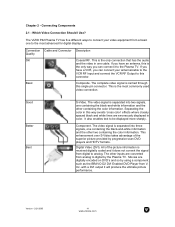
... video signal is received digitally coded and it does not convert the signal from analog to analog. All of the superior picture provided by the Plasma TV. with a DVI output it to this way avoids 'cross color' effects where closely spaced black and white lines are erroneously displayed in one... you have an antenna, this single pin connector. Movies are converted from digital to digital by progressive scan DVD players and HDTV formats. The VIZIO P42 Plasma TV has five different ways to connect your antenna/cable to the VCR RF Input and connect the VCR RF Output to the...
... video signal is received digitally coded and it does not convert the signal from analog to analog. All of the superior picture provided by the Plasma TV. with a DVI output it to this way avoids 'cross color' effects where closely spaced black and white lines are erroneously displayed in one... you have an antenna, this single pin connector. Movies are converted from digital to digital by progressive scan DVD players and HDTV formats. The VIZIO P42 Plasma TV has five different ways to connect your antenna/cable to the VCR RF Input and connect the VCR RF Output to the...
User Guide
Page 16
... your new P42 Plasma TV - Version - 2/21/2005 15 www.vizioce.com Note: a) Use TMDS signals conforming to the Plasma TV and DVD player....the DVI input in the rear of the Plasma TV. Connect a DVI-D cable to the DVI output of your DVD ... other end to the DVI input of your Plasma TV supports High-bandwidth Content Protection (HDCP). The TMDS..., and Composite inputs. Select DVI using the INPUT button on your Plasma TV. 3. Connecting Your DVD Player You have a digital interface compliant with...next to the Plasma TV and your Plasma TV. 4. 2.2 - Connect the Audio on the power to the...
... your new P42 Plasma TV - Version - 2/21/2005 15 www.vizioce.com Note: a) Use TMDS signals conforming to the Plasma TV and DVD player....the DVI input in the rear of the Plasma TV. Connect a DVI-D cable to the DVI output of your DVD ... other end to the DVI input of your Plasma TV supports High-bandwidth Content Protection (HDCP). The TMDS..., and Composite inputs. Select DVI using the INPUT button on your Plasma TV. 3. Connecting Your DVD Player You have a digital interface compliant with...next to the Plasma TV and your Plasma TV. 4. 2.2 - Connect the Audio on the power to the...
User Guide
Page 17
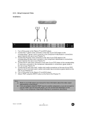
... Pr (red color) connector in the Component Video/Audio In connections (green band) in the rear of the Plasma TV. If you are already using the INPUT button on the rear of your Plasma TV. 5. Connect the Pb (blue color) connector on the front of your DVD player to the corresponding Pb ... (green band) in the Component Video/Audio IN group of the product. 2.2.2 - Connect the Pr (red color) connector on the rear of your Plasma TV. 4. Select YPbPr using the YPbPr input for another component, or you do not want to use the YPbPr input for more information about the video...
... Pr (red color) connector in the Component Video/Audio In connections (green band) in the rear of the Plasma TV. If you are already using the INPUT button on the rear of your Plasma TV. 5. Connect the Pb (blue color) connector on the front of your DVD player to the corresponding Pb ... (green band) in the Component Video/Audio IN group of the product. 2.2.2 - Connect the Pr (red color) connector on the rear of your Plasma TV. 4. Select YPbPr using the YPbPr input for another component, or you do not want to use the YPbPr input for more information about the video...
User Guide
Page 18
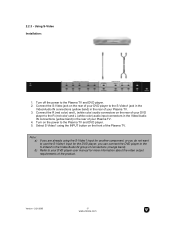
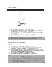
... of your DVD player to the S-Video1 jack in the Video/Audio IN connections (yellow band) in the rear of your DVD player to the Plasma TV and DVD player. 2. 2.2.3 - Connect the S-Video jack on the front of the product. Refer to use the S-Video1 input for more information about the ... R (red color) and L (white color) audio input connectors in the Video/Audio IN connections (yellow band) in the Video/Audio IN group of your Plasma TV. 3. Select S-Video1 using the S-Video1 input for another component, or you can connect the DVD player to the S-Video2 in the rear of your DVD...
... of your DVD player to the S-Video1 jack in the Video/Audio IN connections (yellow band) in the rear of your DVD player to the Plasma TV and DVD player. 2. 2.2.3 - Connect the S-Video jack on the front of the product. Refer to use the S-Video1 input for more information about the ... R (red color) and L (white color) audio input connectors in the Video/Audio IN connections (yellow band) in the Video/Audio IN group of your Plasma TV. 3. Select S-Video1 using the S-Video1 input for another component, or you can connect the DVD player to the S-Video2 in the rear of your DVD...
User Guide
Page 19
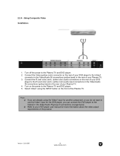
...) connector on the rear of your DVD player to the Video1 connector in the Video/Audio IN connections (yellow band) in the rear of your Plasma TV. 4. Connect the R (red color) and L (white color) audio connectors on the rear of your DVD player to the R (red color) and L (white... color) audio input connectors in the Video/Audio IN connections (yellow band) in the rear of your Plasma TV. 3. Note: a) b) If you are already using the INPUT button on the power to the Plasma TV and DVD player. 2. 2.2.4 - Turn on the front of the product. Select Video1 using the Video1 input...
...) connector on the rear of your DVD player to the Video1 connector in the Video/Audio IN connections (yellow band) in the rear of your Plasma TV. 4. Connect the R (red color) and L (white color) audio connectors on the rear of your DVD player to the R (red color) and L (white... color) audio input connectors in the Video/Audio IN connections (yellow band) in the rear of your Plasma TV. 3. Note: a) b) If you are already using the INPUT button on the power to the Plasma TV and DVD player. 2. 2.2.4 - Turn on the front of the product. Select Video1 using the Video1 input...
User Guide
Page 20
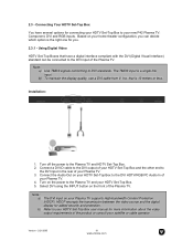
... DVI (Digital Visual Interface) standard can decide which option is the right one for more information about the video output requirements of your new P42 Plasma TV: Component, DVI and RGB inputs. To maintain the display quality, use a DVI cable from V, Inc. that have several options for added security ... display for connecting your satellite or cable operator. Version - 2/21/2005 19 www.vizioce.com Note: a) b) Use TMDS signals conforming to the Plasma TV and HDTV Set-Top Box. 2. Refer to the DVI input in the rear of the product or consult your HDTV Set-Top Box to the...
... DVI (Digital Visual Interface) standard can decide which option is the right one for more information about the video output requirements of your new P42 Plasma TV: Component, DVI and RGB inputs. To maintain the display quality, use a DVI cable from V, Inc. that have several options for added security ... display for connecting your satellite or cable operator. Version - 2/21/2005 19 www.vizioce.com Note: a) b) Use TMDS signals conforming to the Plasma TV and HDTV Set-Top Box. 2. Refer to the DVI input in the rear of the product or consult your HDTV Set-Top Box to the...
User Guide
Page 21
... Installation: 1. Turn off the power to the RGB output of your satellite or cable operator. 2.4 - Connect a 15-pin D-Sub RGB cable to the Plasma TV and HDTV Set-Top Box. 2. Note: Refer to your HDTV Set-Top Box user manual for more information about the video output requirements of the... component, or you do not want to the RGB IN input in the Video/Audio IN group of your Plasma TV. 3. Select RGB using the INPUT button on the power to the Plasma TV and your Plasma TV. 4. Connect the R (red color) and L (white color) audio connectors on your HDTV Set-Top Box. 5. b) Refer ...
... Installation: 1. Turn off the power to the RGB output of your satellite or cable operator. 2.4 - Connect a 15-pin D-Sub RGB cable to the Plasma TV and HDTV Set-Top Box. 2. Note: Refer to your HDTV Set-Top Box user manual for more information about the video output requirements of the... component, or you do not want to the RGB IN input in the Video/Audio IN group of your Plasma TV. 3. Select RGB using the INPUT button on the power to the Plasma TV and your Plasma TV. 4. Connect the R (red color) and L (white color) audio connectors on your HDTV Set-Top Box. 5. b) Refer ...
User Guide
Page 22
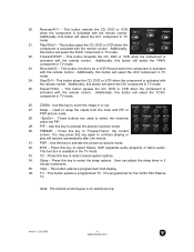
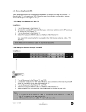
... the RF connector on the front of your antenna or cable box to the Plasma TV and VCR. 2. Select TV1 using the INPUT button on the rear of the Plasma TV. 5. Connect the coaxial (RF) connector from your Plasma TV. 3. See page 30 for connecting your antenna or cable to your VCR. ...- Select TV1 using the INPUT button on the rear of the Plasma TV. Using the Antenna through your new P42 Plasma TV directly to the Plasma TV. 2. Connect the "Output to TV" (RF Out or Antenna Out) connector on the rear of your Plasma TV. 3. Turn on the power to the RF connector on the ...
... the RF connector on the front of your antenna or cable box to the Plasma TV and VCR. 2. Select TV1 using the INPUT button on the rear of the Plasma TV. 5. Connect the coaxial (RF) connector from your Plasma TV. 3. See page 30 for connecting your antenna or cable to your VCR. ...- Select TV1 using the INPUT button on the rear of the Plasma TV. Using the Antenna through your new P42 Plasma TV directly to the Plasma TV. 2. Connect the "Output to TV" (RF Out or Antenna Out) connector on the rear of your Plasma TV. 3. Turn on the power to the RF connector on the ...
User Guide
Page 23
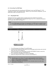
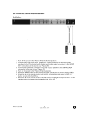
... color) audio output connectors in the AUDIO OUT connections in the rear of your Plasma TV. 4. Connect the subwoofer connector on the remote control until Subwoofer is highlighted and press the SELECT button to the Plasma TV and speakers. 5. Press the MENU button on the remote control to activate the ...Sub Menu. 7. Turn on -screen display (OSD). 6. Turn off the power to the SUBWOOFER connection in the rear of your Plasma TV. 3. Press the f on the rear of your speaker to the Plasma TV and external speakers. 2. Connecting External Amplified Speakers Installation: 1.
... color) audio output connectors in the AUDIO OUT connections in the rear of your Plasma TV. 4. Connect the subwoofer connector on the remote control until Subwoofer is highlighted and press the SELECT button to the Plasma TV and speakers. 5. Press the MENU button on the remote control to activate the ...Sub Menu. 7. Turn on -screen display (OSD). 6. Turn off the power to the SUBWOOFER connection in the rear of your Plasma TV. 3. Press the f on the rear of your speaker to the Plasma TV and external speakers. 2. Connecting External Amplified Speakers Installation: 1.
User Guide
Page 24
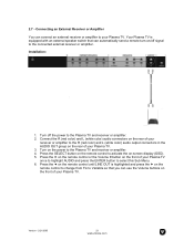
...button on the remote control to activate the on the power to Variable so that can automatically send a remote turn-on the front of your Plasma TV. Press the d on the remote control until LINE OUT is equipped with an external speaker switch that you can connect an external receiver or... and press the ENTER button to the R (red color) and L (white color) audio output connectors in the AUDIO OUT group on the front of your Plasma TV. 3. Connect the R (red color) and L (white color) audio connectors on the rear of your receiver or amplifier to select this Sub Menu. 6. 2.7 - Connecting ...
...button on the remote control to activate the on the power to Variable so that can automatically send a remote turn-on the front of your Plasma TV. Press the d on the remote control until LINE OUT is equipped with an external speaker switch that you can connect an external receiver or... and press the ENTER button to the R (red color) and L (white color) audio output connectors in the AUDIO OUT group on the front of your Plasma TV. 3. Connect the R (red color) and L (white color) audio connectors on the rear of your receiver or amplifier to select this Sub Menu. 6. 2.7 - Connecting ...
User Guide
Page 25
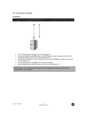
Turn off the power to the Plasma TV and your Plasma TV. 4. Version - 2/21/2005 24 www.vizioce.com Select RGB using the INPUT button on your computer to the DVI HDTV/RBG PC Audio In at ... computer. 5. Note: Refer to the RGB input in the rear of your computer user manual for more information about the video output requirements of the Plasma TV. 2.8 - Connecting a Computer Installation: 1. Connect the Audio Out on the front of the product. Connect a 15-pin D-sub RGB cable to the RGB output of your...
Turn off the power to the Plasma TV and your Plasma TV. 4. Version - 2/21/2005 24 www.vizioce.com Select RGB using the INPUT button on your computer to the DVI HDTV/RBG PC Audio In at ... computer. 5. Note: Refer to the RGB input in the rear of your computer user manual for more information about the video output requirements of the Plasma TV. 2.8 - Connecting a Computer Installation: 1. Connect the Audio Out on the front of the product. Connect a 15-pin D-sub RGB cable to the RGB output of your...


