Service Manual
Page 6
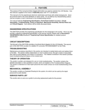
... Exploded Drawing for the system, for detailed product specification. Do Not Copy vx500-1 CIRCUIT DESCRIPTIONS The first part of a detailed I/O connector PIN ASSIGNMENT for the LCD Monitor. And this SECTION provides a functional block diagram for the PCBs. Do ...flow chart for this manual provides integral information you need to detect errors, through a series of 1024x768 pixels color TFT LCD Monitor. ViewSonic Corporation 3 Confidential - 2. The manual includes Engineering Specification, Front Panel Control description, Circuit Description, Troubleshooting, Theory of...
... Exploded Drawing for the system, for detailed product specification. Do Not Copy vx500-1 CIRCUIT DESCRIPTIONS The first part of a detailed I/O connector PIN ASSIGNMENT for the LCD Monitor. And this SECTION provides a functional block diagram for the PCBs. Do ...flow chart for this manual provides integral information you need to detect errors, through a series of 1024x768 pixels color TFT LCD Monitor. ViewSonic Corporation 3 Confidential - 2. The manual includes Engineering Specification, Front Panel Control description, Circuit Description, Troubleshooting, Theory of...
Service Manual
Page 7
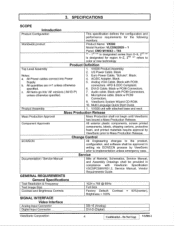
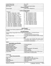
... ** - 1st "*" is designated series from 0-9, 2 nd "*" is designated for the following monitors: Worldwide product Product Name: VX500 Model Number: VLCDS22825 -1 Panel: CMO M150X2 - All Items go into Power Supply. ViewSonic System Wizard CD-ROM. 10. HPD & DDC Compliant. 6. Euro Power Cable, "Schuko". VX500 Product Assembly 2. Microphone cable. GENERAL REQUIREMENTS General Specifications Test Resolution & Frequency...
... ** - 1st "*" is designated series from 0-9, 2 nd "*" is designated for the following monitors: Worldwide product Product Name: VX500 Model Number: VLCDS22825 -1 Panel: CMO M150X2 - All Items go into Power Supply. ViewSonic System Wizard CD-ROM. 10. HPD & DDC Compliant. 6. Euro Power Cable, "Schuko". VX500 Product Assembly 2. Microphone cable. GENERAL REQUIREMENTS General Specifications Test Resolution & Frequency...
Service Manual
Page 8
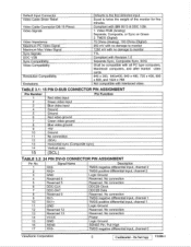
... ASSIGNMENT Pin No. 1 Signal Name RX2- No connection 9 RX1- TMDS negative differential input, channel 0 ViewSonic Corporation 5 Confidential - Video RGB (Analog) Separate, Composite, or Sync on Green 2. Description TMDS negative ... Data 8 Reserved 8 Reserved. Compliant with interlaced video. No connection 14 VCCX Power 15 GND Logic Ground 16 SENS SENSE Pin, Pull High 17 RX0- No connection 13 ...Reserved 12 Reserved. Do Not Copy VX500-1 TMDS (Digital) 75 Ohms (Analog), 100 Ohms (Digital) 950 mV with no damage to monitor 1250 mV with no damage to ...
... ASSIGNMENT Pin No. 1 Signal Name RX2- No connection 9 RX1- TMDS negative differential input, channel 0 ViewSonic Corporation 5 Confidential - Video RGB (Analog) Separate, Composite, or Sync on Green 2. Description TMDS negative ... Data 8 Reserved 8 Reserved. Compliant with interlaced video. No connection 14 VCCX Power 15 GND Logic Ground 16 SENS SENSE Pin, Pull High 17 RX0- No connection 13 ...Reserved 12 Reserved. Do Not Copy VX500-1 TMDS (Digital) 75 Ohms (Analog), 100 Ohms (Digital) 950 mV with no damage to monitor 1250 mV with no damage to ...
Service Manual
Page 11
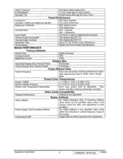
...VESA 800 x 600 @72Hz, 48.077kHz 10. LCD Panel Panel Characteristics Panel Type Type Active Size Pixel Arrangement Pixel Pitch ViewSonic Corporation CMO - Vertical Refresh Rate Maximum Pixel Clock ...monitor is in power saving. VESA 800 x 600 @56Hz, 35.156kHz 8. VESA 1024 x 768 @60Hz, 48.4kHz 13. T03 Active Matrix TFT, (MVA technology) 304.1mm (H) x 228.1 mm (V) RGB Vertical Stripe 0.297 mm 8 Confidential - Do Not Copy VX500...0kHz 14. VESA 1024 x 768 @72Hz, 58.036kHz 15. GTF GTF The system shall recognize GTF timings which are allowable within horizontal/ vertical / dot rate / ...
...VESA 800 x 600 @72Hz, 48.077kHz 10. LCD Panel Panel Characteristics Panel Type Type Active Size Pixel Arrangement Pixel Pitch ViewSonic Corporation CMO - Vertical Refresh Rate Maximum Pixel Clock ...monitor is in power saving. VESA 800 x 600 @56Hz, 35.156kHz 8. VESA 1024 x 768 @60Hz, 48.4kHz 13. T03 Active Matrix TFT, (MVA technology) 304.1mm (H) x 228.1 mm (V) RGB Vertical Stripe 0.297 mm 8 Confidential - Do Not Copy VX500...0kHz 14. VESA 1024 x 768 @72Hz, 58.036kHz 15. GTF GTF The system shall recognize GTF timings which are allowable within horizontal/ vertical / dot rate / ...
Service Manual
Page 12
...+/-0.03 Preset Color Temperature Adjustability Each color preset shall be individually controlled. Red, Green, and Blue shall be adjustable. ViewSonic Corporation 9 Confidential - Glass Treatment Anti Glare (Hard coating 3H) # of the monitor Temperature Drift Image shall not drift or lose fine-tune adjustment. IMAGE PERFORMANCE Factory Defaults Preset Color 6500K (Primary) Contrast... frequency range of Backlights Backlight Life 4 CCFL edge-light (2 top/2 bottom) 50,000 Hours (Min) @ 25°C & IL=7mA Panel Performance Luminance - Do Not Copy VX500-1
...+/-0.03 Preset Color Temperature Adjustability Each color preset shall be individually controlled. Red, Green, and Blue shall be adjustable. ViewSonic Corporation 9 Confidential - Glass Treatment Anti Glare (Hard coating 3H) # of the monitor Temperature Drift Image shall not drift or lose fine-tune adjustment. IMAGE PERFORMANCE Factory Defaults Preset Color 6500K (Primary) Contrast... frequency range of Backlights Backlight Life 4 CCFL edge-light (2 top/2 bottom) 50,000 Hours (Min) @ 25°C & IL=7mA Panel Performance Luminance - Do Not Copy VX500-1
Service Manual
Page 21
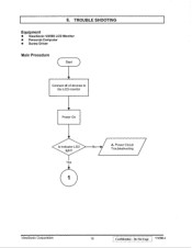
TROUBLE SHOOTING Equipment • ViewSonic VX500 LCD Monitor • Personal Computer • Screw Driver Main Procedure ( Start ) Connect all of devices to the LCD monitor Power On Is indicator LED light? Do Not Copy VX500-1 Power Circuit Troubleshooting / ViewSonic Corporation 18 Confidential - Yes 1 A. 6.
TROUBLE SHOOTING Equipment • ViewSonic VX500 LCD Monitor • Personal Computer • Screw Driver Main Procedure ( Start ) Connect all of devices to the LCD monitor Power On Is indicator LED light? Do Not Copy VX500-1 Power Circuit Troubleshooting / ViewSonic Corporation 18 Confidential - Yes 1 A. 6.
Service Manual
Page 30
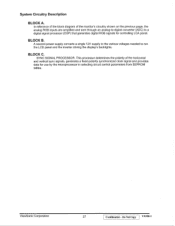
... circuit control parameters from EEPROM tables. SYNC SIGNAL PROCESSOR. System Circuitry Description BLOCK A. BLOCK C. This processor determines the polarity of the monitor's circuitry shown on the previous page, the analog RGB inputs are amplified and sent through an analog-to-digital converter (ADC) to run ...the LCD panel and the inverter driving the display's backlights. BLOCK B. In reference of the block diagram of the horizontal and vertical sync signals, ...
... circuit control parameters from EEPROM tables. SYNC SIGNAL PROCESSOR. System Circuitry Description BLOCK A. BLOCK C. This processor determines the polarity of the monitor's circuitry shown on the previous page, the analog RGB inputs are amplified and sent through an analog-to-digital converter (ADC) to run ...the LCD panel and the inverter driving the display's backlights. BLOCK B. In reference of the block diagram of the horizontal and vertical sync signals, ...


