Sony BRC-Z700 Command List
Page 3
... mix the automatic and manual settings. In VISCA, up to seven peripheral devices like the BRC-Z700 can be connected to the addresses, 1, 2, 3... The devices on the connected BRC-Z700 cameras to 1 through 7 (manual setting mode) The addresses of the peripheral devices will be manually set the camera address selectors on the network are as follows. in a daisy chain. The address of Sony Corporation. 3 When the camera address selector is a protocol...
... mix the automatic and manual settings. In VISCA, up to seven peripheral devices like the BRC-Z700 can be connected to the addresses, 1, 2, 3... The devices on the connected BRC-Z700 cameras to 1 through 7 (manual setting mode) The addresses of the peripheral devices will be manually set the camera address selectors on the network are as follows. in a daisy chain. The address of Sony Corporation. 3 When the camera address selector is a protocol...

Sony BRC-Z700 Command List
Page 5
... used , using the socket number of the ACK message. FF QQ1) = Command/Inquiry, RR2) = category code 1) QQ = 01 (Command), 09 (Inquiry) 2) RR = 00 (Interface), 04 (camera 1), 06 (Pan/Tilter) X = 1 to 7: BRC-Z700 address For actual values to 7: BRC-Z700 address, Y = socket number Error message "Command canceled" will contain 0. No ACK message is returned for this command, but this is...
... used , using the socket number of the ACK message. FF QQ1) = Command/Inquiry, RR2) = category code 1) QQ = 01 (Command), 09 (Inquiry) 2) RR = 00 (Interface), 04 (camera 1), 06 (Pan/Tilter) X = 1 to 7: BRC-Z700 address For actual values to 7: BRC-Z700 address, Y = socket number Error message "Command canceled" will contain 0. No ACK message is returned for this command, but this is...

Sony BRC-Z700 Command List
Page 6
...network administration • Address Sets an address of the BRC-Z700, be re-set when this message is not guaranteed. When cleared, the operation currently being executed is received. Packet Address 88 30 01 FF Network Change X0 38 FF X = 9 to F: BRC-Z700 address +8 (For reply ... Sony) HHHH = Model ID 0501: BRC-H700 0502: BRU-H700 0505: BRC-Z700 JJJJ = ROM revision KK = Maximum socket # (02) X = 1 to 7: BRC-Z700 address (For inquiry packet) X = 9 to the network. Use when initializing the network, and receiving the following network change message. • Network Change...
...network administration • Address Sets an address of the BRC-Z700, be re-set when this message is not guaranteed. When cleared, the operation currently being executed is received. Packet Address 88 30 01 FF Network Change X0 38 FF X = 9 to F: BRC-Z700 address +8 (For reply ... Sony) HHHH = Model ID 0501: BRC-H700 0502: BRU-H700 0505: BRC-Z700 JJJJ = ROM revision KK = Maximum socket # (02) X = 1 to 7: BRC-Z700 address (For inquiry packet) X = 9 to the network. Use when initializing the network, and receiving the following network change message. • Network Change...
Sony BRC-Z700 Operating Instructions
Page 2
...) Instruction for each country taking the application and environment into account. 2 BRC-Z700 Serial No. WARNING Use the Sony MPA-AC1 AC power adapter provided with the regulations and laws for installing the equipment on the bottom. For the customers in the residential area. These limits are located on the ceiling: After the installation, ensure the connection...
...) Instruction for each country taking the application and environment into account. 2 BRC-Z700 Serial No. WARNING Use the Sony MPA-AC1 AC power adapter provided with the regulations and laws for installing the equipment on the bottom. For the customers in the residential area. These limits are located on the ceiling: After the installation, ensure the connection...

Sony BRC-Z700 Operating Instructions
Page 3
... Products 8 System Configuration 11 Operating a BRC-Z700 Camera Using the Supplied Remote Commander 11 Operating a BRC-Z700 Camera Using the RM- controllable Cameras in Memory - Table of Contents Getting Started Precautions 5 Phenomena Specific to the HDV Video Equipment 17 Location and Function of Contents BR300 Remote Control Unit 11 Operating Multiple BRC-Z700 Cameras Using the RM-BR300 Remote Control Unit 12 Operating a BRC-Z700 Camera from a Long Distance...
... Products 8 System Configuration 11 Operating a BRC-Z700 Camera Using the Supplied Remote Commander 11 Operating a BRC-Z700 Camera Using the RM- controllable Cameras in Memory - Table of Contents Getting Started Precautions 5 Phenomena Specific to the HDV Video Equipment 17 Location and Function of Contents BR300 Remote Control Unit 11 Operating Multiple BRC-Z700 Cameras Using the RM-BR300 Remote Control Unit 12 Operating a BRC-Z700 Camera from a Long Distance...
Sony BRC-Z700 Operating Instructions
Page 4
... Unit 66 Connecting a Video Switcher 67 Connecting a Sync Signal Generator 68 Appendix List of Messages 70 Troubleshooting 71 Menu Configuration 73 Presetting Items 78 Specifications 81 Dimensions 83 Pin Assignments 86 Wiring Diagram of VISCA RS-422 Connection 89 Using the VISCA RS-422 Connector Plug ...... 90 4 Table of the Camera Moving to a Preset Position 52 Installation and Connections Installation 53 Attaching...
... Unit 66 Connecting a Video Switcher 67 Connecting a Sync Signal Generator 68 Appendix List of Messages 70 Troubleshooting 71 Menu Configuration 73 Presetting Items 78 Specifications 81 Dimensions 83 Pin Assignments 86 Wiring Diagram of VISCA RS-422 Connection 89 Using the VISCA RS-422 Connector Plug ...... 90 4 Table of the Camera Moving to a Preset Position 52 Installation and Connections Installation 53 Attaching...

Sony BRC-Z700 Operating Instructions
Page 15
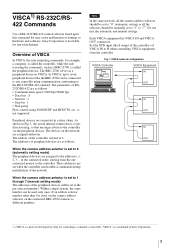
...cameras supporting the VISCA protocol such as EVI-D30/D30P, EVI-D70/D70P, EVI-D100/ D100P, EVI-HD1, BRC-H700 and BRC-300/300P remotely using a single RM-BR300 Remote Control Unit • To perform pan/tilt and zoom operations using the joystick • To control the BRC-Z700 cameras remotely... from a distance up to 1,000 m (3,281 feet) by transmitting the video signal and control signal using the Optical Fiber Cable System configuration VISCA-controllable camera HD video monitor, VTR, etc. VISCA-controllable camera BRC-Z700 CCFC-M100HG BRU-H700 BRC-Z700 ...
...cameras supporting the VISCA protocol such as EVI-D30/D30P, EVI-D70/D70P, EVI-D100/ D100P, EVI-HD1, BRC-H700 and BRC-300/300P remotely using a single RM-BR300 Remote Control Unit • To perform pan/tilt and zoom operations using the joystick • To control the BRC-Z700 cameras remotely... from a distance up to 1,000 m (3,281 feet) by transmitting the video signal and control signal using the Optical Fiber Cable System configuration VISCA-controllable camera HD video monitor, VTR, etc. VISCA-controllable camera BRC-Z700 CCFC-M100HG BRU-H700 BRC-Z700 ...
Sony BRC-Z700 Operating Instructions
Page 17
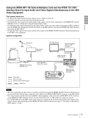
... the BRU-H700. • You cannot operate pan/tilt and zoom with HDV video equipment connected to the i.LINK (HDV) OUT connector on the BRU-H700 if you : • To operate the camera remotely from a distance up to 1,000m (3,281 feet) • To perform pan/...simultaneously to the HDV video equipment System configuration BRC-Z700 Microphone BRBK-MF1 HD Optical Multiplex Card Microphone amplifier HD video monitor HDV VTR equipped with the i.Link connector i.Link cable HFBK-TS1 HDV Interface Board CCFC-M100HG Optical Fiber Cable R L i.Link (HDV) HFBK-TS1 AUDIO IN CAMERA IN EXT SYNC ...
... the BRU-H700. • You cannot operate pan/tilt and zoom with HDV video equipment connected to the i.LINK (HDV) OUT connector on the BRU-H700 if you : • To operate the camera remotely from a distance up to 1,000m (3,281 feet) • To perform pan/...simultaneously to the HDV video equipment System configuration BRC-Z700 Microphone BRBK-MF1 HD Optical Multiplex Card Microphone amplifier HD video monitor HDV VTR equipped with the i.Link connector i.Link cable HFBK-TS1 HDV Interface Board CCFC-M100HG Optical Fiber Cable R L i.Link (HDV) HFBK-TS1 AUDIO IN CAMERA IN EXT SYNC ...

Sony BRC-Z700 Operating Instructions
Page 19
... Card. O EXT SYNC IN connector Accepts external video sync signals. You can assign the camera address "1" to the VISCA RS-232C IN connector of the camera. The slot cover is not used. Normally set to the camera at the factory. S DC IN 12V connector Connect the supplied AC power adaptor. For details, see "Installing the Camera in the daisy chain...
... Card. O EXT SYNC IN connector Accepts external video sync signals. You can assign the camera address "1" to the VISCA RS-232C IN connector of the camera. The slot cover is not used. Normally set to the camera at the factory. S DC IN 12V connector Connect the supplied AC power adaptor. For details, see "Installing the Camera in the daisy chain...

Sony BRC-Z700 Operating Instructions
Page 20
...set different camera numbers. For the camera number setting, see "Operating Multiple Cameras with the same Remote Commander. C DATA SCREEN button Press this button to an AC outlet. F POWER switch Press this button once to display PAGE1 and twice to reset the pan/tilt position. When you install the cameras close to zoom quickly. When the menu is connected...to 6 to adjust the focus automatically. To reset the direction of the camera. E L/R DIRECTION SET button Hold down this button and press the REV button to change the set using the IR SELECT switch on page 43....
...set different camera numbers. For the camera number setting, see "Operating Multiple Cameras with the same Remote Commander. C DATA SCREEN button Press this button to an AC outlet. F POWER switch Press this button once to display PAGE1 and twice to reset the pan/tilt position. When you install the cameras close to zoom quickly. When the menu is connected...to 6 to adjust the focus automatically. To reset the direction of the camera. E L/R DIRECTION SET button Hold down this button and press the REV button to change the set using the IR SELECT switch on page 43....
Sony BRC-Z700 Operating Instructions
Page 21
... Instructions supplied with the BRIGHT indicator lit): Adjusts the value of the brightness of the VALUE/R control and BRIGHT/B control. Overview Installing batteries Two R6 (size AA) batteries (not supplied) Caution To avoid risk of the RM-BR300 Remote Control Unit when it is used with BRC-Z700 cameras. RM-BR300 Remote Control Unit (not supplied) This manual...
... Instructions supplied with the BRIGHT indicator lit): Adjusts the value of the brightness of the VALUE/R control and BRIGHT/B control. Overview Installing batteries Two R6 (size AA) batteries (not supplied) Caution To avoid risk of the RM-BR300 Remote Control Unit when it is used with BRC-Z700 cameras. RM-BR300 Remote Control Unit (not supplied) This manual...

Sony BRC-Z700 Operating Instructions
Page 25
...Remote Control Unit. Select HD-SDI or SD-SDI signals with the BRC-Z700 only) BRBK-HSD1 1 SDI OUTPUT 2 SD HD A SDI OUTPUT connectors (BNC type) Supplies down the RESET button on the BRU-H700 HD Optical Multiplex Unit via the Optical Fiber Cable. For the connection to 5 (Camera address selectors) Set the address... input audio signals from a microphone, etc., it should be connected with a microphone amplifier so that conform to ON for 38400bps, or OFF for the VISCA communication settings. Note Set the switches before turning on the power of the camera. Note The audio input on...
...Remote Control Unit. Select HD-SDI or SD-SDI signals with the BRC-Z700 only) BRBK-HSD1 1 SDI OUTPUT 2 SD HD A SDI OUTPUT connectors (BNC type) Supplies down the RESET button on the BRU-H700 HD Optical Multiplex Unit via the Optical Fiber Cable. For the connection to 5 (Camera address selectors) Set the address... input audio signals from a microphone, etc., it should be connected with a microphone amplifier so that conform to ON for 38400bps, or OFF for the VISCA communication settings. Note Set the switches before turning on the power of the camera. Note The audio input on...

Sony BRC-Z700 Operating Instructions
Page 46
... the power of the Remote Control Unit. For setting the camera address selector, see "Installation" (page 53) and "Connections" (page 61). While holding down the POWER button, press the CAMERA button corresponding to "0." Note Be sure to turn on/off the illumination, press the PANEL LIGHT button again. PANEL LIGHT 1 Connect the camera to be reset to the position stored...
... the power of the Remote Control Unit. For setting the camera address selector, see "Installation" (page 53) and "Connections" (page 61). While holding down the POWER button, press the CAMERA button corresponding to "0." Note Be sure to turn on/off the illumination, press the PANEL LIGHT button again. PANEL LIGHT 1 Connect the camera to be reset to the position stored...

Sony BRC-Z700 Operating Instructions
Page 47
... speed changes according to 7 automatically in the connected order. 4 Press the POWER button on the screen, incline the joystick in the table below. To assign camera addresses manually Set one of the camera addresses, 1 to 7, using the camera address selectors on , performing the pan/tilt reset action automatically. 2 Press the CAMERA button corresponding to the camera you want to set a limit on the Remote Control...
... speed changes according to 7 automatically in the connected order. 4 Press the POWER button on the screen, incline the joystick in the table below. To assign camera addresses manually Set one of the camera addresses, 1 to 7, using the camera address selectors on , performing the pan/tilt reset action automatically. 2 Press the CAMERA button corresponding to the camera you want to set a limit on the Remote Control...

Sony BRC-Z700 Operating Instructions
Page 57
... steps to ensure that the load of the cables connected does not cause problems. 10 The SONY and/or HD nameplates can be turned upside down, if necessary. To remove the camera 1 Remove the three screws used to attach the camera in the front of the ceiling bracket (A) aligned ... ceiling bracket (A) into the spaces prepared in the ceiling bracket (B) with the a hole in step 8 of "Installation on a ceiling (example)." 2 Turn the camera with the camera clockwise. 9 Connect the cables to the connectors on the ceiling bracket (B), and temporarily attach them by turning the ceiling bracket (A) with...
... steps to ensure that the load of the cables connected does not cause problems. 10 The SONY and/or HD nameplates can be turned upside down, if necessary. To remove the camera 1 Remove the three screws used to attach the camera in the front of the ceiling bracket (A) aligned ... ceiling bracket (A) into the spaces prepared in the ceiling bracket (B) with the a hole in step 8 of "Installation on a ceiling (example)." 2 Turn the camera with the camera clockwise. 9 Connect the cables to the connectors on the ceiling bracket (B), and temporarily attach them by turning the ceiling bracket (A) with...

Sony BRC-Z700 Operating Instructions
Page 61
... power adaptor and AC power cord to connect the camera to an AC outlet. 1 2 3 4 5 6 7 8 9 OFF ON R DATA MIX VISCA RS-422 OFF ON 75 IR SELECT 1 2 3 RGB/COMPONENT IN VISCA RS-232C OUT EXT SYNC IN VIDEO S VIDEO DC IN 12V DC IN 12V AC ...load of the cables connected does not cause problems. To remove the camera 1 Remove the three screws used to attach the camera in a high position (example)." 2 Turn the camera with the bracket clockwise to the connectors on the rear of "Installation on a shelf, etc. Installation and Connections 61 Connections 8 Connect the cables to remove...
... power adaptor and AC power cord to connect the camera to an AC outlet. 1 2 3 4 5 6 7 8 9 OFF ON R DATA MIX VISCA RS-422 OFF ON 75 IR SELECT 1 2 3 RGB/COMPONENT IN VISCA RS-232C OUT EXT SYNC IN VIDEO S VIDEO DC IN 12V DC IN 12V AC ...load of the cables connected does not cause problems. To remove the camera 1 Remove the three screws used to attach the camera in a high position (example)." 2 Turn the camera with the bracket clockwise to the connectors on the rear of "Installation on a shelf, etc. Installation and Connections 61 Connections 8 Connect the cables to remove...
Sony BRC-Z700 Operating Instructions
Page 70
... to H PHASE in the connection of the camera and turn on , if a connection problem occurs in the SYSTEM menu. Turn off the power of the Optical Fiber Cable between the camera and the HD Optical Multiplex Unit. Indicators on the Remote Control Unit. *PUSH ENTER BUTTON This message appears when you changed setting becomes effective. Reset the pan/tilt position...
... to H PHASE in the connection of the camera and turn on , if a connection problem occurs in the SYSTEM menu. Turn off the power of the Optical Fiber Cable between the camera and the HD Optical Multiplex Unit. Indicators on the Remote Control Unit. *PUSH ENTER BUTTON This message appears when you changed setting becomes effective. Reset the pan/tilt position...

Sony BRC-Z700 Operating Instructions
Page 71
... is not displayed on . open the menu and set to the camera. monitor connected to ON. Check that the connection to any other address than "0 (AUTO)." go . Check the connection between the camera and video monitor. The panning or tilting range is not correct. Change the PAN-TILT LIMIT setting in your Sony dealer. The camera cannot be turned on the monitor screen...
... is not displayed on . open the menu and set to the camera. monitor connected to ON. Check that the connection to any other address than "0 (AUTO)." go . Check the connection between the camera and video monitor. The panning or tilting range is not correct. Change the PAN-TILT LIMIT setting in your Sony dealer. The camera cannot be turned on the monitor screen...

Sony BRC-Z700 Operating Instructions
Page 86
RXD IN+ TXD IN - At YPbPr At YPbPr At RGB At RGB COMPONENT COMPONENT setting (at setting (at setting setting (at VD) SYNC) VD) 1 Pr-OUT Pr-OUT R-OUT R-OUT 2 Y-OUT Y-OUT G-OUT G-OUT 3 Pb-OUT Pb-OUT B-OUT B-OUT 4 GND GND GND GND 5 GND ... DTR OUT DSR OUT TXD OUT GND RXD OUT GND No Connection No Connection Analog RGB/COMPONENT (D-sub 15-pin) RGB/COMPONENT Pin Function No. VD-OUT OUT 15 NC NC NC NC Appendix 86 Specifications RXD OUT+ TXD OUT - Pin Assignments BRC-Z700 Video Camera VISCA RS-422 connector (connector plug 9-pin) VISCA RS-422 123456789...
RXD IN+ TXD IN - At YPbPr At YPbPr At RGB At RGB COMPONENT COMPONENT setting (at setting (at setting setting (at VD) SYNC) VD) 1 Pr-OUT Pr-OUT R-OUT R-OUT 2 Y-OUT Y-OUT G-OUT G-OUT 3 Pb-OUT Pb-OUT B-OUT B-OUT 4 GND GND GND GND 5 GND ... DTR OUT DSR OUT TXD OUT GND RXD OUT GND No Connection No Connection Analog RGB/COMPONENT (D-sub 15-pin) RGB/COMPONENT Pin Function No. VD-OUT OUT 15 NC NC NC NC Appendix 86 Specifications RXD OUT+ TXD OUT - Pin Assignments BRC-Z700 Video Camera VISCA RS-422 connector (connector plug 9-pin) VISCA RS-422 123456789...
Sony BRC-Z700 BRBK-HSD1-HDSDI Card Tech Specs
Page 1
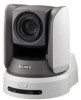
... the Sony BRC-Z700 HD 3CMOS Color Video Camera. For the customers in Canada This Class A digital apparatus complies with the limits for EMC and product safety is Sony Corporation, 1-7-1 Konan, Minato-ku, Tokyo, Japan. This equipment generates, uses, and can radiate radio frequency energy and, if not installed and used to connect peripherals must accept any service or...
... the Sony BRC-Z700 HD 3CMOS Color Video Camera. For the customers in Canada This Class A digital apparatus complies with the limits for EMC and product safety is Sony Corporation, 1-7-1 Konan, Minato-ku, Tokyo, Japan. This equipment generates, uses, and can radiate radio frequency energy and, if not installed and used to connect peripherals must accept any service or...
