
User Manual
Page 7
...Contents vii Chapter 1 1 Specifications 1 Mainboard Specifications 2 Mainboard Layout 4 Back Panel Layout 5 Chapter 2 7 Installation 7 CPU 8 Memory Module Installation 10 Connecting the Power Supply 11 Back Panel Ports 12 Connectors 13 Jumpers 20 Slots 22 Chapter 3 23 BIOS Setup 23 Entering Setup 24 Control Keys 25 Navigating the BIOS... 38 Advanced Chipset Features 39 AGP & P2P Bridge Control 41 CPU & PCI Bus Control 43 Integrated Peripherals 44 VIA OnChip PCI Device 45 USB Device Setting 46 Power Management Setup 48 Wakeup Event Detect 50 PNP/PCI Configurations 52
...Contents vii Chapter 1 1 Specifications 1 Mainboard Specifications 2 Mainboard Layout 4 Back Panel Layout 5 Chapter 2 7 Installation 7 CPU 8 Memory Module Installation 10 Connecting the Power Supply 11 Back Panel Ports 12 Connectors 13 Jumpers 20 Slots 22 Chapter 3 23 BIOS Setup 23 Entering Setup 24 Control Keys 25 Navigating the BIOS... 38 Advanced Chipset Features 39 AGP & P2P Bridge Control 41 CPU & PCI Bus Control 43 Integrated Peripherals 44 VIA OnChip PCI Device 45 USB Device Setting 46 Power Management Setup 48 Wakeup Event Detect 50 PNP/PCI Configurations 52
User Manual
Page 19
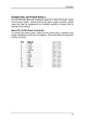
Installation CONNECTING THE POWER SUPPLY The VIA EPIA-NX Nano-ITX mainboard supports a Nano-ITX power supply for the power system. Nano-ITX 12-Pin Power Connector To connect the power supply, make sure that no damage will be caused. Pin Signal 1 +3.3V 2 +3.3V 3 +3.3V 4 +5VSUS 5 GND 6 +12V 7 -PSON 8 +5V 9 GND 10 +5V 11 GND 12 PWRGD ...
Installation CONNECTING THE POWER SUPPLY The VIA EPIA-NX Nano-ITX mainboard supports a Nano-ITX power supply for the power system. Nano-ITX 12-Pin Power Connector To connect the power supply, make sure that no damage will be caused. Pin Signal 1 +3.3V 2 +3.3V 3 +3.3V 4 +5VSUS 5 GND 6 +12V 7 -PSON 8 +5V 9 GND 10 +5V 11 GND 12 PWRGD ...

User Manual
Page 26
... 3 BLON 4 NC 5 BLON 6 BR_CNTR 7 GND 8 GND LPC Connector: LPC This pin connector is for supplying power to the backlight of the LCD panel. Chapter 2 Inverter Connectors: INVERTER1 / INVERTER2 The mainboard provides 2 inverters for LPC devices as well as panel power select jumper. 1 Pin Signal 1 PVDD1_PWR 3 PVDD1_PWR 5 PVDD2_PWR 7 PVDD2_PWR 9 LPC_AD1 11 -PCI_RST1 13 LPC_AD0...
... 3 BLON 4 NC 5 BLON 6 BR_CNTR 7 GND 8 GND LPC Connector: LPC This pin connector is for supplying power to the backlight of the LCD panel. Chapter 2 Inverter Connectors: INVERTER1 / INVERTER2 The mainboard provides 2 inverters for LPC devices as well as panel power select jumper. 1 Pin Signal 1 PVDD1_PWR 3 PVDD1_PWR 5 PVDD2_PWR 7 PVDD2_PWR 9 LPC_AD1 11 -PCI_RST1 13 LPC_AD0...

User Manual
Page 28
... is on will cause system boot failure. Short = Master; Clear CMOS: CLEAR_CMOS The onboard CMOS RAM stores system configuration data and has an onboard battery power supply. Setting 1 2 3 Normal Operation ON ON OFF Clear CMOS setting OFF ON ON Normal: 123 Clear: Caution: 123 Except when clearing the RTC RAM, never remove...
... is on will cause system boot failure. Short = Master; Clear CMOS: CLEAR_CMOS The onboard CMOS RAM stores system configuration data and has an onboard battery power supply. Setting 1 2 3 Normal Operation ON ON OFF Clear CMOS setting OFF ON ON Normal: 123 Clear: Caution: 123 Except when clearing the RTC RAM, never remove...

User Manual
Page 30
... Slot Order 1 INT B# Order 2 INT C# Order 3 INT D# Order 4 INT A# Compact Flash Type I Connector: CF1 This CF1 connector allows you to the microprocessor. First unplug the power supply before adding or removing expansion cards. PCI Interrupt Request Routing The IRQ (interrupt request line) are hardware lines over which devices can send interrupt signals...
... Slot Order 1 INT B# Order 2 INT C# Order 3 INT D# Order 4 INT A# Compact Flash Type I Connector: CF1 This CF1 connector allows you to the microprocessor. First unplug the power supply before adding or removing expansion cards. PCI Interrupt Request Routing The IRQ (interrupt request line) are hardware lines over which devices can send interrupt signals...

User Manual
Page 56
...all system contexts. The system context is saved to main memory, and context is a power-down the hard disk. AwardBIOS CMOS Setup Utility Power Management Setup ACPI Suspend Type Power Management Option HDD Power Down Suspend Mode Video Off Option Video Off Method MODEM Use IRQ Soft-Off by ... Setting S1(POS) S3(STR) S1 & S3 Description S1/Power On Suspend (POS) is supplied only to select S1 or S3. In this state, power is a low power state. Power Management Option Settings: [User Define, Min Saving, Max Saving] HDD Power Down Sets the length of time for a period of inactivity ...
...all system contexts. The system context is saved to main memory, and context is a power-down the hard disk. AwardBIOS CMOS Setup Utility Power Management Setup ACPI Suspend Type Power Management Option HDD Power Down Suspend Mode Video Off Option Video Off Method MODEM Use IRQ Soft-Off by ... Setting S1(POS) S3(STR) S1 & S3 Description S1/Power On Suspend (POS) is supplied only to select S1 or S3. In this state, power is a low power state. Power Management Option Settings: [User Define, Min Saving, Max Saving] HDD Power Down Sets the length of time for a period of inactivity ...