User Manual
Page 4
... sign of breakage 12. Caution: Only use the appropriate battery specified for future reference. 3. Safety Instructions 1. Lay this product. Never pour any of the power source and adjust properly 110/220V before setting it up. 5. Do not reuse, recharge, or reheat an old battery. Keep this User's Manual for this equipment on card or module. 9. The openings on the...
... sign of breakage 12. Caution: Only use the appropriate battery specified for future reference. 3. Safety Instructions 1. Lay this product. Never pour any of the power source and adjust properly 110/220V before setting it up. 5. Do not reuse, recharge, or reheat an old battery. Keep this User's Manual for this equipment on card or module. 9. The openings on the...

User Manual
Page 7
...2 Mainboard Layout 4 Back Panel Layout 5 Chapter 2 7 Installation 7 CPU 8 Memory Module Installation 10 Connecting the Power Supply 11 Back Panel Ports 12 Connectors 13 Jumpers 20 Slots 22 Chapter 3 23 BIOS Setup 23 Entering Setup 24 Control Keys 25 Navigating the BIOS Menus 26 Getting Help 27 Main Menu 28 Standard CMOS Features 30 IDE Drives 31 Advanced BIOS Features 32 CPU Feature 36 Hard Disk Boot Priority 38 Advanced Chipset Features 39 AGP & P2P Bridge Control 41 CPU & PCI Bus Control 43 Integrated Peripherals 44 VIA OnChip PCI Device 45 USB Device Setting 46...
...2 Mainboard Layout 4 Back Panel Layout 5 Chapter 2 7 Installation 7 CPU 8 Memory Module Installation 10 Connecting the Power Supply 11 Back Panel Ports 12 Connectors 13 Jumpers 20 Slots 22 Chapter 3 23 BIOS Setup 23 Entering Setup 24 Control Keys 25 Navigating the BIOS Menus 26 Getting Help 27 Main Menu 28 Standard CMOS Features 30 IDE Drives 31 Advanced BIOS Features 32 CPU Feature 36 Hard Disk Boot Priority 38 Advanced Chipset Features 39 AGP & P2P Bridge Control 41 CPU & PCI Bus Control 43 Integrated Peripherals 44 VIA OnChip PCI Device 45 USB Device Setting 46...

User Manual
Page 10
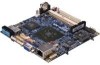
Chapter 1 MAINBOARD SPECIFICATIONS CPU • VIA C7® 1.0GHz NanoBGA2 processor Chipset • VIA CX700 Advanced All-in-One chipset Graphics • Integrated UniChrome™ Pro II 3D/2D AGP graphics with MPEG-2 video decoding acceleration Audio • VIA VT1708A High Definition Audio Codec Memory • 1 x DDR2 533 SODIMM slot (up to 1 GB) Expansion Slot • 1 x Mini-PCI slot IDE • 1 x UltraDMA 133/100 connector (2.54mm, 40-pin) Serial ATA • 2 x SATA connectors LAN • VIA VT6107 10/100 Mbps...
Chapter 1 MAINBOARD SPECIFICATIONS CPU • VIA C7® 1.0GHz NanoBGA2 processor Chipset • VIA CX700 Advanced All-in-One chipset Graphics • Integrated UniChrome™ Pro II 3D/2D AGP graphics with MPEG-2 video decoding acceleration Audio • VIA VT1708A High Definition Audio Codec Memory • 1 x DDR2 533 SODIMM slot (up to 1 GB) Expansion Slot • 1 x Mini-PCI slot IDE • 1 x UltraDMA 133/100 connector (2.54mm, 40-pin) Serial ATA • 2 x SATA connectors LAN • VIA VT6107 10/100 Mbps...

User Manual
Page 11
... LAN port • 1 x VGA port Onboard I connector (shared with IDE, master / slave select by EPIA products with LPC 4/8Mbit flash memory capacity Form Factor • Nano-ITX (8-layer) • 12cm X 12cm Note: 1. When connecting two single-channel panels, the two panels must have the same timing specification and resolution. 3 Due to the hardware limitation, DDR2 SDRAM chips organized as 128Mb x 8 bank cannot be supported by jumpers) • 1 x PS2 Mouse/Keyboard pin connector • 1 x Audio pin connector...
... LAN port • 1 x VGA port Onboard I connector (shared with IDE, master / slave select by EPIA products with LPC 4/8Mbit flash memory capacity Form Factor • Nano-ITX (8-layer) • 12cm X 12cm Note: 1. When connecting two single-channel panels, the two panels must have the same timing specification and resolution. 3 Due to the hardware limitation, DDR2 SDRAM chips organized as 128Mb x 8 bank cannot be supported by jumpers) • 1 x PS2 Mouse/Keyboard pin connector • 1 x Audio pin connector...

User Manual
Page 18
Available DDR2 SDRAM Configurations Refer to 1GB. Slot Module Size SODIMM 64MB, 128MB, 256MB, 512MB, 1GB Maximum supported system memory Total 64MB-1GB 64MB-1GB 10 Insert the SODIMM module at a 45 degree angle. Push the SODIMM module back towards the board until the clips lock the module in place. Chapter 2 MEMORY MODULE INSTALLATION Memory Slot: DDR2_SODIMM The VIA EPIA-NX Nano-ITX mainboard provides one SODIMM slot for DDR2 533 SDRAM memory modules and supports memory sizes up to the table below for available DDR2 SDRAM configurations on the mainboard.
Available DDR2 SDRAM Configurations Refer to 1GB. Slot Module Size SODIMM 64MB, 128MB, 256MB, 512MB, 1GB Maximum supported system memory Total 64MB-1GB 64MB-1GB 10 Insert the SODIMM module at a 45 degree angle. Push the SODIMM module back towards the board until the clips lock the module in place. Chapter 2 MEMORY MODULE INSTALLATION Memory Slot: DDR2_SODIMM The VIA EPIA-NX Nano-ITX mainboard provides one SODIMM slot for DDR2 533 SDRAM memory modules and supports memory sizes up to the table below for available DDR2 SDRAM configurations on the mainboard.

User Manual
Page 28
...; Short = Master; Setting the jumper while the system is off. Removing the cap will damage the mainboard. Return the jumper to change the settings of the mainboard functions using the jumpers. To reset the CMOS settings, set the jumper on pins 2 and 3 while the system is on CLEAR_CMOS1 jumper default position. This section will damage the mainboard. Clear CMOS: CLEAR_CMOS The onboard CMOS RAM stores system configuration data and has an onboard battery power supply. Chapter 2 JUMPERS The mainboard provides jumpers for CF Type I connector...
...; Short = Master; Setting the jumper while the system is off. Removing the cap will damage the mainboard. Return the jumper to change the settings of the mainboard functions using the jumpers. To reset the CMOS settings, set the jumper on pins 2 and 3 while the system is on CLEAR_CMOS1 jumper default position. This section will damage the mainboard. Clear CMOS: CLEAR_CMOS The onboard CMOS RAM stores system configuration data and has an onboard battery power supply. Chapter 2 JUMPERS The mainboard provides jumpers for CF Type I connector...

User Manual
Page 30
The "PCI & LAN" IRQ pins are necessary. First unplug the power supply before adding or removing expansion cards. Chapter 2 SLOTS Mini Peripheral Component Interconnect: MINIPCI The miniPCI slot allows you to connect to a passive 50-pin Type I adapter. 22 Read the documentation for the expansion card to see if any changes to the system are typically connected to the PCI bus INT A# ~ INT D# pins as follows: miniPCI Slot Order 1 INT...
The "PCI & LAN" IRQ pins are necessary. First unplug the power supply before adding or removing expansion cards. Chapter 2 SLOTS Mini Peripheral Component Interconnect: MINIPCI The miniPCI slot allows you to connect to a passive 50-pin Type I adapter. 22 Read the documentation for the expansion card to see if any changes to the system are typically connected to the PCI bus INT A# ~ INT D# pins as follows: miniPCI Slot Order 1 INT...

User Manual
Page 39
... size of the storage device Number of cylinders Number of heads Write precompensation Cylinder location of the landing zone Number of the menu. The hard disk will not work properly if you select "Manual", make sure the information is a table that details required hard drive information when using the "Manual" mode. AwardBIOS CMOS Setup Utility IDE Channel 0 Master [Press Enter] Item Help [Auto] [Auto] 0 MB Menu Level To auto-detect the HDD's size, head... BIOS Setup IDE DRIVES IDE HDD Auto-Detection IDE Channel 0 Master Access Mode...
... size of the storage device Number of cylinders Number of heads Write precompensation Cylinder location of the landing zone Number of the menu. The hard disk will not work properly if you select "Manual", make sure the information is a table that details required hard drive information when using the "Manual" mode. AwardBIOS CMOS Setup Utility IDE Channel 0 Master [Press Enter] Item Help [Auto] [Auto] 0 MB Menu Level To auto-detect the HDD's size, head... BIOS Setup IDE DRIVES IDE HDD Auto-Detection IDE Channel 0 Master Access Mode...

User Manual
Page 41
... Enabled Disabled Description Enable alternate boot device No alternate boot device allowed Boot Up NumLock Status Set the NumLock status when the system is powered on. Setting LS120 Hard Disk CD-ROM ZIP100 USB-FDD USB-ZIP USB-CDROM Legacy LAN Disabled Description Boot from LS-120 drive Boot from the HDD Boot from CD-ROM Boot from ATAPI ZIP drive Boot from USB floppy drive Boot from USB ZIP drive Boot from USB CDROM Boot from network drive Disable the boot device sequence Boot Other Device Enables the system to boot from a depressed key. BIOS Setup First/Second/Third Boot Device Set...
... Enabled Disabled Description Enable alternate boot device No alternate boot device allowed Boot Up NumLock Status Set the NumLock status when the system is powered on. Setting LS120 Hard Disk CD-ROM ZIP100 USB-FDD USB-ZIP USB-CDROM Legacy LAN Disabled Description Boot from LS-120 drive Boot from the HDD Boot from CD-ROM Boot from ATAPI ZIP drive Boot from USB floppy drive Boot from USB ZIP drive Boot from USB CDROM Boot from network drive Disable the boot device sequence Boot Other Device Enables the system to boot from a depressed key. BIOS Setup First/Second/Third Boot Device Set...
User Manual
Page 42
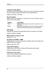
Settings: [Non-OS2, OS2] Video BIOS Shadow Enabled copies Video BIOS to repeat the signal from the depressed key. Settings: [Enabled, Disabled] 34 Settings: [250, 500, 750, 1000] Security Option Selects whether the password is powered on the system. Setting Setup System Description Password prompt appears only when end users try to run BIOS Setup APIC Mode Enables APIC (Advanced Programmable Interrupt Controller) functionality. Settings: [Enabled, Disabled] MPS Variation Control for OS Settings: [1.1, 1.4] OS Select for DRAM > 64MB Select OS2...
Settings: [Non-OS2, OS2] Video BIOS Shadow Enabled copies Video BIOS to repeat the signal from the depressed key. Settings: [Enabled, Disabled] 34 Settings: [250, 500, 750, 1000] Security Option Selects whether the password is powered on the system. Setting Setup System Description Password prompt appears only when end users try to run BIOS Setup APIC Mode Enables APIC (Advanced Programmable Interrupt Controller) functionality. Settings: [Enabled, Disabled] MPS Variation Control for OS Settings: [1.1, 1.4] OS Select for DRAM > 64MB Select OS2...

User Manual
Page 50
Settings: [Auto, Manual] AGP Fast Write This item is used to auto or manual. Settings: [Enabled, Disabled] AGP Master 1 WS Write Settings: [Enabled, Disabled] AGP Master 1 WS Read Settings: [Enabled, Disabled] AGP 3.0 Calibration Cycle Settings: [Enabled, Disabled] VGA Share Memory Size Settings: [Disabled, 32M, 64M, 128M] Direct Frame Buffer Settings: [Enabled, Disabled] 42 Chapter 3 AGP Driving Control This item is used to signal driving current on AGP cards to enable or disable the caching of display data for the video memory of the processor.
Settings: [Auto, Manual] AGP Fast Write This item is used to auto or manual. Settings: [Enabled, Disabled] AGP Master 1 WS Write Settings: [Enabled, Disabled] AGP Master 1 WS Read Settings: [Enabled, Disabled] AGP 3.0 Calibration Cycle Settings: [Enabled, Disabled] VGA Share Memory Size Settings: [Disabled, 32M, 64M, 128M] Direct Frame Buffer Settings: [Enabled, Disabled] 42 Chapter 3 AGP Driving Control This item is used to signal driving current on AGP cards to enable or disable the caching of display data for the video memory of the processor.

User Manual
Page 53
BIOS Setup VIA ONCHIP PCI DEVICE Azalia HDA Controller OnBoard LAN Boot ROM Phoenix - AwardBIOS CMOS Setup Utility VIA OnChip PCI Device [Auto] [Disabled] Item Help Menu Level : Move Enter: Select F5: Previous Values +/-/PU/PD: Value F10: Save F6: Fail-Safe Defaults ESC: Exit F1: General Help F7: Optimized Defaults Azalia HAD Controller Settings: [Auto, Disabled] OnBoard LAN Boot ROM Settings: [Enabled, Disabled] 45
BIOS Setup VIA ONCHIP PCI DEVICE Azalia HDA Controller OnBoard LAN Boot ROM Phoenix - AwardBIOS CMOS Setup Utility VIA OnChip PCI Device [Auto] [Disabled] Item Help Menu Level : Move Enter: Select F5: Previous Values +/-/PU/PD: Value F10: Save F6: Fail-Safe Defaults ESC: Exit F1: General Help F7: Optimized Defaults Azalia HAD Controller Settings: [Auto, Disabled] OnBoard LAN Boot ROM Settings: [Enabled, Disabled] 45

User Manual
Page 54
.../low speed mode 46 AwardBIOS CMOS Setup Utility USB Device Setting [Enabled] [Enabled] [High Speed] [Enabled] [Enabled] *** USB Mass Storage Device Boot Setting *** UFDDA USB Floppy UFDDB USB Floppy No Device [Auto mode] No Device [Auto mode] No Device [Auto mode] No Device [Auto mode] No Device [Auto mode] No Device [Auto mode] No Device [Auto mode] No Device [Auto mode] Item Help Menu Level [Enable] or [Disable] Universal Host Controller Interface for Universal Serial Bus : Move Enter: Select F5: Previous Values +/-/PU/PD: Value F10: Save F6: Fail-Safe Defaults ESC...
.../low speed mode 46 AwardBIOS CMOS Setup Utility USB Device Setting [Enabled] [Enabled] [High Speed] [Enabled] [Enabled] *** USB Mass Storage Device Boot Setting *** UFDDA USB Floppy UFDDB USB Floppy No Device [Auto mode] No Device [Auto mode] No Device [Auto mode] No Device [Auto mode] No Device [Auto mode] No Device [Auto mode] No Device [Auto mode] No Device [Auto mode] Item Help Menu Level [Enable] or [Disable] Universal Host Controller Interface for Universal Serial Bus : Move Enter: Select F5: Previous Values +/-/PU/PD: Value F10: Save F6: Fail-Safe Defaults ESC...
User Manual
Page 55
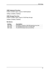
The USB MSD always boot up as floppy disk. The USB MSD always boot up type. BIOS Setup USB Keyboard Function Enable or disable Legacy support of USB Keyboard Settings: [Enabled, Disabled] USB Storage Function Enable or disable Legacy support of USB Mass Storage Settings: [Enabled, Disabled] No Device Setting Auto mode FDD mode HDD mode Description According to contents of USB MSD decide boot up as hard disc. 47
The USB MSD always boot up as floppy disk. The USB MSD always boot up type. BIOS Setup USB Keyboard Function Enable or disable Legacy support of USB Keyboard Settings: [Enabled, Disabled] USB Storage Function Enable or disable Legacy support of USB Mass Storage Settings: [Enabled, Disabled] No Device Setting Auto mode FDD mode HDD mode Description According to contents of USB MSD decide boot up as hard disc. 47

User Manual
Page 59
... resume from a suspended state. Resume Time (hh:mm:ss) The field specifies the time for "RTC Alarm Resume". Settings: [Disabled, Enabled] Date (of Month) The field specifies the date for "RTC Alarm Resume". 51 BIOS Setup PS2 Keyboard Power On Settings: [Disabled, Enabled] PS2 Mouse Power On Settings: [Disabled, Enabled] PowerOn by PCI Card Enables activity detected from any PCI card to automatically power on the system. Such PCI cards include LAN, onboard USB ports, etc.
... resume from a suspended state. Resume Time (hh:mm:ss) The field specifies the time for "RTC Alarm Resume". Settings: [Disabled, Enabled] Date (of Month) The field specifies the date for "RTC Alarm Resume". 51 BIOS Setup PS2 Keyboard Power On Settings: [Disabled, Enabled] PS2 Mouse Power On Settings: [Disabled, Enabled] PowerOn by PCI Card Enables activity detected from any PCI card to automatically power on the system. Such PCI cards include LAN, onboard USB ports, etc.
User Manual
Page 60
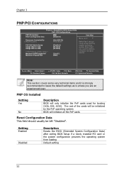
... PnP operating system BIOS will only initialize the PnP cards used for booting (VGA, IDE, SCSI). AwardBIOS CMOS Setup Utility PnP / PCI Configurations PNP OS Installed Reset Configuration Data [No] [Disabled] Resources Controlled By x IRQ Resources [Auto(ESCD)] Press Enter PCI/VGA Palette Snoop Assign IRQ For VGA Assign IRQ For USB [Disabled] [Enabled] [Enabled] ** PCI Express relative items ** Maximum ASPM supported Maximum Payload Size [L0s&L1] [4096] Item Help Menu Level Select Yes if you are using a Plug and Play capable...
... PnP operating system BIOS will only initialize the PnP cards used for booting (VGA, IDE, SCSI). AwardBIOS CMOS Setup Utility PnP / PCI Configurations PNP OS Installed Reset Configuration Data [No] [Disabled] Resources Controlled By x IRQ Resources [Auto(ESCD)] Press Enter PCI/VGA Palette Snoop Assign IRQ For VGA Assign IRQ For USB [Disabled] [Enabled] [Enabled] ** PCI Express relative items ** Maximum ASPM supported Maximum Payload Size [L0s&L1] [4096] Item Help Menu Level Select Yes if you are using a Plug and Play capable...
User Manual
Page 61
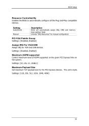
... Payload Size Set maximum TLP payload size for VGA and USB devices. The unit is byte. BIOS Setup Resource Controlled By Enables the BIOS to automatically configure all the Plug-and-Play compatible devices. Setting Auto(ESCD) Manual Description BIOS will automatically assign IRQ, DMA and memory base address fields Unlocks "IRQ Resources" for manual configuration PCI/VGA Palette Snoop Settings: [Disabled, Enabled] Assign IRQ For VGA/USB Assign IRQ for the PCI Express devices. Settings: [Disabled, Enabled] Maximum ASPM supported Control maximum level of ASPM supported on...
... Payload Size Set maximum TLP payload size for VGA and USB devices. The unit is byte. BIOS Setup Resource Controlled By Enables the BIOS to automatically configure all the Plug-and-Play compatible devices. Setting Auto(ESCD) Manual Description BIOS will automatically assign IRQ, DMA and memory base address fields Unlocks "IRQ Resources" for manual configuration PCI/VGA Palette Snoop Settings: [Disabled, Enabled] Assign IRQ For VGA/USB Assign IRQ for the PCI Express devices. Settings: [Disabled, Enabled] Maximum ASPM supported Control maximum level of ASPM supported on...
User Manual
Page 64
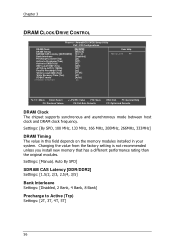
... read CMD (Twtr) Write Recovery Time (Twr) RDSAIT mode x RDSAIT selection [By SPD] [Manual] [2.5 / 4] [Disabled] [4T] [07T] [4T] [25T] [3T] [2T] [1T/2T] [4T] [Auto] 03 Item Help Menu Level : Move Enter: Select F5: Previous Values +/-/PU/PD: Value F10: Save F6: Fail-Safe Defaults ESC: Exit F1: General Help F7: Optimized Defaults DRAM Clock The chipset supports synchronous and asynchronous mode between host clock and DRAM clock frequency.
... read CMD (Twtr) Write Recovery Time (Twr) RDSAIT mode x RDSAIT selection [By SPD] [Manual] [2.5 / 4] [Disabled] [4T] [07T] [4T] [25T] [3T] [2T] [1T/2T] [4T] [Auto] 03 Item Help Menu Level : Move Enter: Select F5: Previous Values +/-/PU/PD: Value F10: Save F6: Fail-Safe Defaults ESC: Exit F1: General Help F7: Optimized Defaults DRAM Clock The chipset supports synchronous and asynchronous mode between host clock and DRAM clock frequency.
User Manual
Page 75
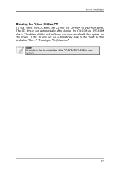
The CD should then appear on the "Start" button and select "Run..." The driver utilities and software menu screen should run automatically, click on the screen. Then type: "D:\Setup.exe". If the CD does not run automatically after closing the CD-ROM or DVD-ROM drive. Note: D: might not be the drive letter of the CD-ROM/DVD-ROM in your system. 67 Driver Installation Running the Driver Utilities CD To start using the CD, insert the CD into the CD-ROM or DVD-ROM drive.
The CD should then appear on the "Start" button and select "Run..." The driver utilities and software menu screen should run automatically, click on the screen. Then type: "D:\Setup.exe". If the CD does not run automatically after closing the CD-ROM or DVD-ROM drive. Note: D: might not be the drive letter of the CD-ROM/DVD-ROM in your system. 67 Driver Installation Running the Driver Utilities CD To start using the CD, insert the CD into the CD-ROM or DVD-ROM drive.
User Manual
Page 76
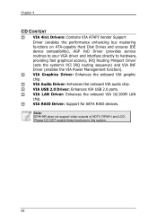
...onboard VIA 10/100M LAN chip. VIA USB 2.0 Driver: Enhances VIA USB 2.0 ports. Chapter 4 CD CONTENT VIA 4in1 Drivers: Contains VIA ATAPI Vendor Support Driver (enables the performance enhancing bus mastering functions on ATA-capable Hard Disk Drives and ensures IDE device compatibility), AGP VxD Driver (provides service routines to your VGA driver and interface directly to hardware, providing fast graphical access), IRQ Routing Miniport Driver (sets the system's PCI IRQ routing sequence) and VIA INF Driver (enables the VIA Power Management function). VIA RAID Driver: Support for SATA RAID...
...onboard VIA 10/100M LAN chip. VIA USB 2.0 Driver: Enhances VIA USB 2.0 ports. Chapter 4 CD CONTENT VIA 4in1 Drivers: Contains VIA ATAPI Vendor Support Driver (enables the performance enhancing bus mastering functions on ATA-capable Hard Disk Drives and ensures IDE device compatibility), AGP VxD Driver (provides service routines to your VGA driver and interface directly to hardware, providing fast graphical access), IRQ Routing Miniport Driver (sets the system's PCI IRQ routing sequence) and VIA INF Driver (enables the VIA Power Management function). VIA RAID Driver: Support for SATA RAID...
