User Manual
Page 3
... not discard used batteries according to User's Manual. • The equipment has dropped and damaged • If the equipment has obvious sign of the power source and adjust properly 110/220V before setting it . Never pour any add-on the enclosure are for air convection hence protects the equipment from humidity. 4. The openings on card or module...
... not discard used batteries according to User's Manual. • The equipment has dropped and damaged • If the equipment has obvious sign of the power source and adjust properly 110/220V before setting it . Never pour any add-on the enclosure are for air convection hence protects the equipment from humidity. 4. The openings on card or module...

User Manual
Page 6
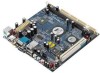
... ii Chapter 1 1 Specifications 1 Mainboard Specifications 2 Mainboard Layout 4 Back Panel Layout 5 Chapter 2 7 Installation 7 CPU 8 Memory Module Installation 10 Connecting the Power Supply 11 Back Panel Ports 12 Connectors 14 Jumpers 19 Slots 20 Chapter 3 21 BIOS Setup 21 Entering Setup 22 Control Keys 23 Navigating the BIOS Menus 24 Getting Help 25 Main Menu 26 Standard CMOS Features 28 IDE Drives 29 Advanced BIOS Features 30 CPU Feature 33 Hard Disk Boot Priority 35 Advanced Chipset Features 36 AGP & P2P Bridge Control 38 CPU & PCI Bus Control 40 TV Output...
... ii Chapter 1 1 Specifications 1 Mainboard Specifications 2 Mainboard Layout 4 Back Panel Layout 5 Chapter 2 7 Installation 7 CPU 8 Memory Module Installation 10 Connecting the Power Supply 11 Back Panel Ports 12 Connectors 14 Jumpers 19 Slots 20 Chapter 3 21 BIOS Setup 21 Entering Setup 22 Control Keys 23 Navigating the BIOS Menus 24 Getting Help 25 Main Menu 26 Standard CMOS Features 28 IDE Drives 29 Advanced BIOS Features 30 CPU Feature 33 Hard Disk Boot Priority 35 Advanced Chipset Features 36 AGP & P2P Bridge Control 38 CPU & PCI Bus Control 40 TV Output...
User Manual
Page 11
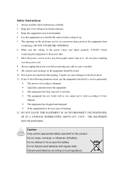
• 1 x Buzzer • 1 x ATX Power connector Specifications Back Panel I/O Ports • 1 x PS/2 mouse port and 1 x PS/2 keyboard port • 1 x RJ-45 LAN port • 1 x Serial port • 1 x VGA port • 2 x USB 2.0 ports • 3 x Audio Jacks: Line-out, Line-in and Mic-in • 1 x RCA port for Composite TV output (optional) or Coaxial S/PDIF • 1 x S-Video port (optional) BIOS • Award BIOS with LPC 4Mbit flash memory capacity Form Factor • Mini-ITX (4 layers) • 17cm X 17cm Note: Due to the hardware...
• 1 x Buzzer • 1 x ATX Power connector Specifications Back Panel I/O Ports • 1 x PS/2 mouse port and 1 x PS/2 keyboard port • 1 x RJ-45 LAN port • 1 x Serial port • 1 x VGA port • 2 x USB 2.0 ports • 3 x Audio Jacks: Line-out, Line-in and Mic-in • 1 x RCA port for Composite TV output (optional) or Coaxial S/PDIF • 1 x S-Video port (optional) BIOS • Award BIOS with LPC 4Mbit flash memory capacity Form Factor • Mini-ITX (4 layers) • 17cm X 17cm Note: Due to the hardware...
User Manual
Page 21
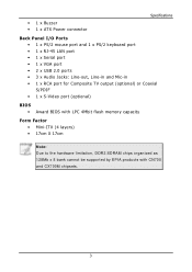
... as a CD player, tape player, etc. The Line-In jack is for pointing devices or other serial devices. Note: The audio ports can be switched to any analog VGA monitor. BIOS Setup VGA Port The 15-pin female VGA connector can be used to connect to Smart 5.1 8-channel audio output. After completing the previous installation, connect the speakers to a Local Area Network (LAN) through a network hub and USB 2.0 devices. These ports allow connection to the 3-jack connectors on your desktop after installing the audio driver.
... as a CD player, tape player, etc. The Line-In jack is for pointing devices or other serial devices. Note: The audio ports can be switched to any analog VGA monitor. BIOS Setup VGA Port The 15-pin female VGA connector can be used to connect to Smart 5.1 8-channel audio output. After completing the previous installation, connect the speakers to a Local Area Network (LAN) through a network hub and USB 2.0 devices. These ports allow connection to the 3-jack connectors on your desktop after installing the audio driver.

User Manual
Page 27
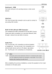
... jumper default position. BIOS Setup JUMPERS The mainboard provides jumpers for selecting between SPDIF and RCA (composite) video. 24 Setting 1 2 3 4 RCA Composite ON ON OFF OFF SPDIF OFF OFF ON ON RCA 13 24 SPDIF 13 19 Return the jumper to change the settings of the mainboard functions using the jumpers. Clear CMOS: CLEAR_CMOS The onboard CMOS RAM stores system configuration data and has an onboard battery power supply. This section will damage the mainboard. it will cause system boot failure...
... jumper default position. BIOS Setup JUMPERS The mainboard provides jumpers for selecting between SPDIF and RCA (composite) video. 24 Setting 1 2 3 4 RCA Composite ON ON OFF OFF SPDIF OFF OFF ON ON RCA 13 24 SPDIF 13 19 Return the jumper to change the settings of the mainboard functions using the jumpers. Clear CMOS: CLEAR_CMOS The onboard CMOS RAM stores system configuration data and has an onboard battery power supply. This section will damage the mainboard. it will cause system boot failure...

User Manual
Page 28
... power supply. The "PCI & LAN" IRQ pins are hardware lines over which devices can send interrupt signals to the PCI bus INT A# ~ INT D# pins as follows: PCI Slot 1 Order 1 INT B# Order 2 INT C# Order 3 INT D# Order 4 INT A# 20 PCI PCI Interrupt Request Routing The IRQ (interrupt request line) are typically connected to the microprocessor. Read the documentation for the expansion card if any changes to insert PCI expansion card...
... power supply. The "PCI & LAN" IRQ pins are hardware lines over which devices can send interrupt signals to the PCI bus INT A# ~ INT D# pins as follows: PCI Slot 1 Order 1 INT B# Order 2 INT C# Order 3 INT D# Order 4 INT A# 20 PCI PCI Interrupt Request Routing The IRQ (interrupt request line) are typically connected to the microprocessor. Read the documentation for the expansion card if any changes to insert PCI expansion card...
User Manual
Page 37
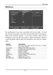
... this match the name of sectors Settings: [0, 1, 2, 3, 4] Settings: [Disabled, Auto] 29 If you enter incorrect information in this channel 0 0 0 0 0 [Auto] [Auto] : Move Enter: Select F5: Previous Values +/-/PU/PD: Value F10: Save F6: Fail-Safe Defaults ESC: Exit F1: General F7: Optimized Defaults Help The specifications of your hard disk vendor or system manufacturer. AwardBIOS CMOS Setup Utility IDE Channel 0 Master [Press Enter] Item Help [Auto] [Auto] 0 MB Menu Level To auto-detect the HDD's size, head...
... this match the name of sectors Settings: [0, 1, 2, 3, 4] Settings: [Disabled, Auto] 29 If you enter incorrect information in this channel 0 0 0 0 0 [Auto] [Auto] : Move Enter: Select F5: Previous Values +/-/PU/PD: Value F10: Save F6: Fail-Safe Defaults ESC: Exit F1: General F7: Optimized Defaults Help The specifications of your hard disk vendor or system manufacturer. AwardBIOS CMOS Setup Utility IDE Channel 0 Master [Press Enter] Item Help [Auto] [Auto] 0 MB Menu Level To auto-detect the HDD's size, head...

User Manual
Page 38
... Option APIC Mode MPS Version Control For OS Display Full Screen Logo Display Small Logo [Press Enter] [Press Enter] [Disabled] [Enabled] [Enabled] [USB-FDD] [CDROM] [Hard Disk] [Enabled] [On] [Disabled] 6 250 [Setup] [Enabled] [1.4] [Enabled] [Disabled] Item Help Menu Level : Move Enter: Select F5: Previous Values +/-/PU/PD: Value F10: Save F6: Fail-Safe Defaults ESC: Exit F1: General F7: Optimized Defaults Help Virus Warning This item is used to enable shorter boot up time. Setting Enabled Disabled Description Shorten Power On Self Test (POST...
... Option APIC Mode MPS Version Control For OS Display Full Screen Logo Display Small Logo [Press Enter] [Press Enter] [Disabled] [Enabled] [Enabled] [USB-FDD] [CDROM] [Hard Disk] [Enabled] [On] [Disabled] 6 250 [Setup] [Enabled] [1.4] [Enabled] [Disabled] Item Help Menu Level : Move Enter: Select F5: Previous Values +/-/PU/PD: Value F10: Save F6: Fail-Safe Defaults ESC: Exit F1: General F7: Optimized Defaults Help Virus Warning This item is used to enable shorter boot up time. Setting Enabled Disabled Description Shorten Power On Self Test (POST...

User Manual
Page 39
Setting LS120 Hard Disk CD-ROM ZIP100 USB-FDD USB-ZIP USB-CDROM Legacy LAN Disabled Description Boot from LS-120 drive Boot from the HDD Boot from CD-ROM Boot from ATAPI ZIP drive Boot from USB floppy drive Boot from USB ZIP drive Boot from USB CDROM Boot from network drive Disable the boot device sequence Boot Other Device Enables the system to boot from alternate devices if the system fails to load the disk operating system. Setting Enabled Disabled Description Enable alternate boot device No alternate boot device allowed Boot Up NumLock Status Set the NumLock status when...
Setting LS120 Hard Disk CD-ROM ZIP100 USB-FDD USB-ZIP USB-CDROM Legacy LAN Disabled Description Boot from LS-120 drive Boot from the HDD Boot from CD-ROM Boot from ATAPI ZIP drive Boot from USB floppy drive Boot from USB ZIP drive Boot from USB CDROM Boot from network drive Disable the boot device sequence Boot Other Device Enables the system to boot from alternate devices if the system fails to load the disk operating system. Setting Enabled Disabled Description Enable alternate boot device No alternate boot device allowed Boot Up NumLock Status Set the NumLock status when...
User Manual
Page 40
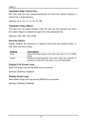
... when the system begins to run BIOS Setup Display Full Screen Logo Show full screen logo during BIOS boot up process. Settings: [Enabled, Disabled] Display Small Logo Show small energy star logo during BIOS boot up process. Settings: [250, 500, 750, 1000] Security Option Selects whether the password is powered on and when end users try to repeat the signal from a depressed key. Chapter 3 Typematic Rate (Chars/Sec) This...
... when the system begins to run BIOS Setup Display Full Screen Logo Show full screen logo during BIOS boot up process. Settings: [Enabled, Disabled] Display Small Logo Show small energy star logo during BIOS boot up process. Settings: [250, 500, 750, 1000] Security Option Selects whether the password is powered on and when end users try to repeat the signal from a depressed key. Chapter 3 Typematic Rate (Chars/Sec) This...
User Manual
Page 44
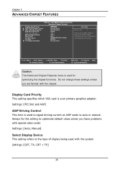
...and PCI slots, configure this setting to optimized default value unless you are display cards on AGP cards to auto or manual. Display Card Priority This setting specifies which VGA card is used with the chipset. Always fix this item for optimizing the chipset functions. AwardBIOS CMOS Setup Utility Advanced Chipset Features Display Card Priority AGP & P2P Bridge Control CPU & PCI Bus Control AGP Driving Control AGP Driving Value Select Display Device Panel Type TV H/W Layout TV Type TV Output Connector [PCI Slot] [Press Enter] [Press Enter] [Auto] DA [CRT] [02] [COMPOSITE+S-Video...
...and PCI slots, configure this setting to optimized default value unless you are display cards on AGP cards to auto or manual. Display Card Priority This setting specifies which VGA card is used with the chipset. Always fix this item for optimizing the chipset functions. AwardBIOS CMOS Setup Utility Advanced Chipset Features Display Card Priority AGP & P2P Bridge Control CPU & PCI Bus Control AGP Driving Control AGP Driving Value Select Display Device Panel Type TV H/W Layout TV Type TV Output Connector [PCI Slot] [Press Enter] [Press Enter] [Auto] DA [CRT] [02] [COMPOSITE+S-Video...
User Manual
Page 46
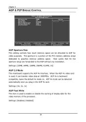
... is used to AGP for the video memory of the processor. Settings: [32MB, 64MB, 128MB, 256MB, 512MB, 1G] AGP 2.0 Mode This mainboard supports the AGP 4x interface. Settings: [Enabled, Disabled] 38 AGP 4x mode can be allocated to enable or disable the caching of the PCI memory address range dedicated to the AGP without any translation. AGP 4x is a portion of display data for video purposes. AwardBIOS CMOS Setup Utility AGP...
... is used to AGP for the video memory of the processor. Settings: [32MB, 64MB, 128MB, 256MB, 512MB, 1G] AGP 2.0 Mode This mainboard supports the AGP 4x interface. Settings: [Enabled, Disabled] 38 AGP 4x mode can be allocated to enable or disable the caching of the PCI memory address range dedicated to the AGP without any translation. AGP 4x is a portion of display data for video purposes. AwardBIOS CMOS Setup Utility AGP...
User Manual
Page 50
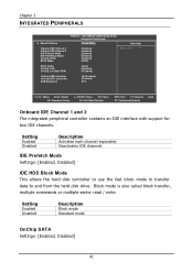
...Lan Boot ROM [Auto] [Enabled] [Disabled] OnChip USB Controller OnChip EHCI Controller USB Emulation [All Enabled] [Enabled] [On] : Move Enter: Select F5: Previous Values +/-/PU/PD: Value F10: Save F6: Fail-Safe Defaults ESC: Exit F1: General F7: Optimized Defaults Help Onboard IDE Channel 1 and 2 The integrated peripheral controller contains an IDE interface with support for two IDE channels. Setting Enabled Disabled Description Activates each channel separately Deactivates IDE channels IDE Prefetch Mode Settings: [Enabled, Disabled] IDE HDD Block Mode This allows the hard disk...
...Lan Boot ROM [Auto] [Enabled] [Disabled] OnChip USB Controller OnChip EHCI Controller USB Emulation [All Enabled] [Enabled] [On] : Move Enter: Select F5: Previous Values +/-/PU/PD: Value F10: Save F6: Fail-Safe Defaults ESC: Exit F1: General F7: Optimized Defaults Help Onboard IDE Channel 1 and 2 The integrated peripheral controller contains an IDE interface with support for two IDE channels. Setting Enabled Disabled Description Activates each channel separately Deactivates IDE channels IDE Prefetch Mode Settings: [Enabled, Disabled] IDE HDD Block Mode This allows the hard disk...
User Manual
Page 51
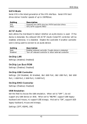
...hard disk drives Only SATA supports RAID AC'97 Audio Auto allows the mainboard to detect whether an audio device is used to connect to "OFF ", do not support any USB device on DOS. Disable the controller if another controller card is being used . When set to an audio device. otherwise, it is detected, the onboard VIA AC'97 (Audio Codec'97) controller will be enabled; Setting Auto Disabled Description Enables onboard controller if audio device is detected Turn off onboard controller to allow external controller OnChip LAN Settings: [Enabled, Disabled] OnChip Lan Boot ROM Settings...
...hard disk drives Only SATA supports RAID AC'97 Audio Auto allows the mainboard to detect whether an audio device is used to connect to "OFF ", do not support any USB device on DOS. Disable the controller if another controller card is being used . When set to an audio device. otherwise, it is detected, the onboard VIA AC'97 (Audio Codec'97) controller will be enabled; Setting Auto Disabled Description Enables onboard controller if audio device is detected Turn off onboard controller to allow external controller OnChip LAN Settings: [Enabled, Disabled] OnChip Lan Boot ROM Settings...

User Manual
Page 56
... PCI Master Event Enables the power management unit to monitor VGA activities. Settings: [Disabled, Enabled] 48 Settings: [Disabled, Enabled] Wake Up On LAN/Ring Enables any PCI card to an active state. Settings: [Disabled, Enabled] VGA Event Enables the power management unit to monitor PCI master activities. Settings: [None, COM] HDD Event Enables the power management unit to an active state. Such PCI cards include LAN card, onboard LAN controller, onboard USB ports, etc. Settings: [Off, On] COM Event Decide whether or not the power management unit should monitor serial port (COM...
... PCI Master Event Enables the power management unit to monitor VGA activities. Settings: [Disabled, Enabled] 48 Settings: [Disabled, Enabled] Wake Up On LAN/Ring Enables any PCI card to an active state. Settings: [Disabled, Enabled] VGA Event Enables the power management unit to monitor PCI master activities. Settings: [None, COM] HDD Event Enables the power management unit to an active state. Such PCI cards include LAN card, onboard LAN controller, onboard USB ports, etc. Settings: [Off, On] COM Event Decide whether or not the power management unit should monitor serial port (COM...

User Manual
Page 58
..., when the operating system is on. AwardBIOS CMOS Setup Utility IRQs Activities [ON] [Enabled] [Enabled] [Disabled] [Disabled] [Disabled] [Disabled] [Disabled] [Disabled] [Disabled] [Enabled] [Enabled] [Enabled] [Disabled] Item Help Menu Level If you choose Disabled, the power management unit will interrupt itself and perform the service required by causing an IRQ to I /O device needs to gain attention of the enabled channels. Settings: [Off, On] IRQ3~IRQ15 Enables or disables the monitoring of the specified IRQ line. Chapter 3 IRQS...
..., when the operating system is on. AwardBIOS CMOS Setup Utility IRQs Activities [ON] [Enabled] [Enabled] [Disabled] [Disabled] [Disabled] [Disabled] [Disabled] [Disabled] [Disabled] [Enabled] [Enabled] [Enabled] [Disabled] Item Help Menu Level If you choose Disabled, the power management unit will interrupt itself and perform the service required by causing an IRQ to I /O device needs to gain attention of the enabled channels. Settings: [Off, On] IRQ3~IRQ15 Enables or disables the monitoring of the specified IRQ line. Chapter 3 IRQS...

User Manual
Page 59
... loading Default setting 51 AwardBIOS CMOS Setup Utility PnP / PCI Configurations PNP OS Installed Reset Configuration Data [No] [Disabled] Resources Controlled By IRQ Resources Assign IRQ For VGA Assign IRQ For USB [Auto(ESCD)] Press Enter [Enabled] [Enabled] Item Help Menu Level Select Yes if you are using a Plug and Play capable operating system. The rest of the cards will be initialized by the PnP operating system BIOS will only initialize the PnP cards used for booting (VGA, IDE...
... loading Default setting 51 AwardBIOS CMOS Setup Utility PnP / PCI Configurations PNP OS Installed Reset Configuration Data [No] [Disabled] Resources Controlled By IRQ Resources Assign IRQ For VGA Assign IRQ For USB [Auto(ESCD)] Press Enter [Enabled] [Enabled] Item Help Menu Level Select Yes if you are using a Plug and Play capable operating system. The rest of the cards will be initialized by the PnP operating system BIOS will only initialize the PnP cards used for booting (VGA, IDE...

User Manual
Page 62
... CPU Clock CPU Clock Ratio Spread Spectrum [By SPD] [Auto By SPD] 2.5/ 4 Disabled 4T 07T 4T 25T 3T [2T] [1T/2T] [4T] [2T Command] [Auto] 03 [Enabled] [100MHz] [ 6 X] [0.25%] Item Help Menu Level : Move Enter: Select F5: Previous Values +/-/PU/PD: Value F10: Save F6: Fail-Safe Defaults ESC: Exit F1: General F7: Optimized Defaults Help DRAM Clock The chipset supports synchronous and asynchronous mode between host clock and DRAM clock frequency...
... CPU Clock CPU Clock Ratio Spread Spectrum [By SPD] [Auto By SPD] 2.5/ 4 Disabled 4T 07T 4T 25T 3T [2T] [1T/2T] [4T] [2T Command] [Auto] 03 [Enabled] [100MHz] [ 6 X] [0.25%] Item Help Menu Level : Move Enter: Select F5: Previous Values +/-/PU/PD: Value F10: Save F6: Fail-Safe Defaults ESC: Exit F1: General F7: Optimized Defaults Help DRAM Clock The chipset supports synchronous and asynchronous mode between host clock and DRAM clock frequency...
User Manual
Page 75
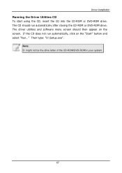
Note: D: might not be the drive letter of the CD-ROM/DVD-ROM in your system. 67 Then type: "D:\Setup.exe". Driver Installation Running the Driver Utilities CD To start using the CD, insert the CD into the CD-ROM or DVD-ROM drive. The driver utilities and software menu screen should run automatically, click on the screen. The CD should then appear on the "Start" button and select "Run..." If the CD does not run automatically after closing the CD-ROM or DVD-ROM drive.
Note: D: might not be the drive letter of the CD-ROM/DVD-ROM in your system. 67 Then type: "D:\Setup.exe". Driver Installation Running the Driver Utilities CD To start using the CD, insert the CD into the CD-ROM or DVD-ROM drive. The driver utilities and software menu screen should run automatically, click on the screen. The CD should then appear on the "Start" button and select "Run..." If the CD does not run automatically after closing the CD-ROM or DVD-ROM drive.
User Manual
Page 76
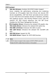
... graphic chip. VIA FIR Driver: Support for SATA RAID devices. Chapter 4 CD CONTENT VIA 4in1 Drivers: Contains VIA ATAPI Vendor Support Driver (enables the performance enhancing bus mastering functions on ATA-capable Hard Disk Drives and ensures IDE device compatibility), AGP VxD Driver (provides service routines to your VGA driver and interface directly to hardware, providing fast graphical access), IRQ Routing Miniport Driver (sets the system's PCI IRQ routing sequence) and VIA INF Driver (enables the VIA Power Management function). VIA USB 2.0 Driver: Enhances VIA USB 2.0 ports. VIA...
... graphic chip. VIA FIR Driver: Support for SATA RAID devices. Chapter 4 CD CONTENT VIA 4in1 Drivers: Contains VIA ATAPI Vendor Support Driver (enables the performance enhancing bus mastering functions on ATA-capable Hard Disk Drives and ensures IDE device compatibility), AGP VxD Driver (provides service routines to your VGA driver and interface directly to hardware, providing fast graphical access), IRQ Routing Miniport Driver (sets the system's PCI IRQ routing sequence) and VIA INF Driver (enables the VIA Power Management function). VIA USB 2.0 Driver: Enhances VIA USB 2.0 ports. VIA...
