
English Owners Manual
Page 4
... plug. 16. Weather Channels are displayed as single digits (Example: 0, 1, 2, 3, etc.). Connect black power lead to positive power source. 17. Connect the antenna here using a PL259 type connector. 15. LO - LED Numerical Channel Display - The connecting wire must use . DC Power Cord with In-line Fuse Holder -...INT - Indicates International Channel Mode. 11. TX (Transmit) - Indicates PTT switch is pressed. 13. Rear Panel Connectors 16 14 15 17 14. ANT. (Antenna) Connector - An external 4 ohm, 4 watt speaker may be connected to this jack. DC Ground Cord -
... plug. 16. Weather Channels are displayed as single digits (Example: 0, 1, 2, 3, etc.). Connect black power lead to positive power source. 17. Connect the antenna here using a PL259 type connector. 15. LO - LED Numerical Channel Display - The connecting wire must use . DC Power Cord with In-line Fuse Holder -...INT - Indicates International Channel Mode. 11. TX (Transmit) - Indicates PTT switch is pressed. 13. Rear Panel Connectors 16 14 15 17 14. ANT. (Antenna) Connector - An external 4 ohm, 4 watt speaker may be connected to this jack. DC Ground Cord -
English Owners Manual
Page 5
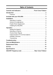
Table of Contents Controls and Indicators Front Cover Foldout Introduction 2 Features 2 Included with your SOLARA 3 Installation 4 Selecting a Location 4 Antenna Considerations 4 Engine Noise Suppression 5 Installing the SOLARA 5 Operation 7 Setting the Squelch 7 Selecting a Channel 8 Channel Auto Repeat 8 Instant Channel 16 Communications 9 USA/INT Channels 9 Transmitting 10 Troubleshooting 12 Care and Maintenance 13 Replacement Parts 13 Service 14 Specifications 15 USA/INT Frequency Lists Rear Cover Foldout 1
Table of Contents Controls and Indicators Front Cover Foldout Introduction 2 Features 2 Included with your SOLARA 3 Installation 4 Selecting a Location 4 Antenna Considerations 4 Engine Noise Suppression 5 Installing the SOLARA 5 Operation 7 Setting the Squelch 7 Selecting a Channel 8 Channel Auto Repeat 8 Instant Channel 16 Communications 9 USA/INT Channels 9 Transmitting 10 Troubleshooting 12 Care and Maintenance 13 Replacement Parts 13 Service 14 Specifications 15 USA/INT Frequency Lists Rear Cover Foldout 1
English Owners Manual
Page 8
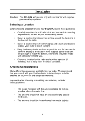
... flow around the heat sink in the back of the radio. • Select a location that you consult with your Uniden dealer in determining a suitable antenna for your vessel and range requirements. Installation Caution: The SOLARA will operate only with nominal 12 volt negative ground battery systems. Selecting a Location Before choosing a location for your...
... flow around the heat sink in the back of the radio. • Select a location that you consult with your Uniden dealer in determining a suitable antenna for your vessel and range requirements. Installation Caution: The SOLARA will operate only with nominal 12 volt negative ground battery systems. Selecting a Location Before choosing a location for your...
English Owners Manual
Page 9
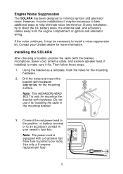
Engine Noise Suppression The SOLARA has been designed to direct the DC battery wires, the antenna lead, and accessory cables away from the engine compartment or ignition and alternator wiring. Contact your Uniden dealer for the mounting surface. Connect the red power lead to the positive (+) battery terminal or to install a noise suppression kit...
Engine Noise Suppression The SOLARA has been designed to direct the DC battery wires, the antenna lead, and accessory cables away from the engine compartment or ignition and alternator wiring. Contact your Uniden dealer for the mounting surface. Connect the red power lead to the positive (+) battery terminal or to install a noise suppression kit...

English Owners Manual
Page 10
Connect the black wire of the power cord to the negative (-) battery terminal or to their appropriate jacks and connectors. Install the radio in the mounting bracket and connect the antenna cable and accessories to a ground source in your vessel's fuse box. 5. Note: Do not use any other mounting knobs than the ones enclosed. Do not insert the screw without attaching the bracket. 6 4.
Connect the black wire of the power cord to the negative (-) battery terminal or to their appropriate jacks and connectors. Install the radio in the mounting bracket and connect the antenna cable and accessories to a ground source in your vessel's fuse box. 5. Note: Do not use any other mounting knobs than the ones enclosed. Do not insert the screw without attaching the bracket. 6 4.
English Owners Manual
Page 17
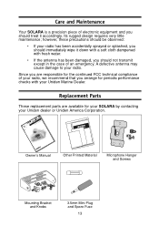
... Parts These replacement parts are responsible for your SOLARA by contacting your radio. however, these precautions should be observed: • If your radio has been accidentally sprayed or splashed, you should immediately wipe it accordingly. A defective antenna may cause damage to your Uniden dealer or Uniden America Corporation. Owner's Manual Other Printed Material Microphone...
... Parts These replacement parts are responsible for your SOLARA by contacting your radio. however, these precautions should be observed: • If your radio has been accidentally sprayed or splashed, you should immediately wipe it accordingly. A defective antenna may cause damage to your Uniden dealer or Uniden America Corporation. Owner's Manual Other Printed Material Microphone...

English Owners Manual
Page 19
... 2nd - 455 kHz 15 Specification General Channels Controls Status Indicators Channel Display Channel Selector Buttons Connectors Size Weight Supply Voltage Antenna Impedance Microphone Speaker Operating Temperature Range Shock and Vibration FCC Approvals Transmitter Power Output Power Requirement Modulation Signal-to-Noise Audio Distortion...OFF/Volume, Squelch 16, INT, LO, TX LED (transmit) LED (Dual 7 segment) UP/DWN select keys CH16, INT, HI/LO Antenna and remote speaker 82mmH x 189mmW x 207mmL 1.2 kg (with Microphone) 13.8V DC negative ground 50Ω, nominal Condenser Microphone with 1000...
... 2nd - 455 kHz 15 Specification General Channels Controls Status Indicators Channel Display Channel Selector Buttons Connectors Size Weight Supply Voltage Antenna Impedance Microphone Speaker Operating Temperature Range Shock and Vibration FCC Approvals Transmitter Power Output Power Requirement Modulation Signal-to-Noise Audio Distortion...OFF/Volume, Squelch 16, INT, LO, TX LED (transmit) LED (Dual 7 segment) UP/DWN select keys CH16, INT, HI/LO Antenna and remote speaker 82mmH x 189mmW x 207mmL 1.2 kg (with Microphone) 13.8V DC negative ground 50Ω, nominal Condenser Microphone with 1000...

