Owners Manual
Page 1
• MRF-25 INSTALLATI MANUAL \\_ Multi-Room "No-Pointing" RF Control of Audio/Video Components HOME THEATERMASTEW Entertainment Made Simple-
• MRF-25 INSTALLATI MANUAL \\_ Multi-Room "No-Pointing" RF Control of Audio/Video Components HOME THEATERMASTEW Entertainment Made Simple-

Owners Manual
Page 2
... change without prior written consent from Universal Remote Control, Inc. UNIVERSAL REMOTE CONTROL INC. All other brand or product names are trademarks or registered trademarks of Universal Remote Control, Inc. No part of Universal Remote Control, Inc. Home Theater Master is copyright protected. X Universal Remote Control° 500 Mamaroneck Avenue, Harrison, NY 10528 Phone: (914) 835-4484 Fax: (914) 835-4532 The information in any form without prior notice. MRF-250 Installation Manual...
... change without prior written consent from Universal Remote Control, Inc. UNIVERSAL REMOTE CONTROL INC. All other brand or product names are trademarks or registered trademarks of Universal Remote Control, Inc. No part of Universal Remote Control, Inc. Home Theater Master is copyright protected. X Universal Remote Control° 500 Mamaroneck Avenue, Harrison, NY 10528 Phone: (914) 835-4484 Fax: (914) 835-4532 The information in any form without prior notice. MRF-250 Installation Manual...

Owners Manual
Page 3
Step by Step 5 Front Blaster Overload 7 Disabling the Front Blaster - Step by Step 7 Controlling An Array of Identical TV's 8 Identical Components - Step by Step 8 Programming For Multiple Equipment Locations II Frequently Asked Questions I2 Specifications 12 Introduction Features and Benefits 2 Parts Guide 2 Front Panel 3 Mounting Plate 3 Power LED 3 Status LED 3 Front Blaster 3 Rear Panel 4 Flashers 4 Power Supply 4 Bottom Panel 4 Receiver ID# 4 A Standard MRF-250 System 5 Standard Installation -
Step by Step 5 Front Blaster Overload 7 Disabling the Front Blaster - Step by Step 7 Controlling An Array of Identical TV's 8 Identical Components - Step by Step 8 Programming For Multiple Equipment Locations II Frequently Asked Questions I2 Specifications 12 Introduction Features and Benefits 2 Parts Guide 2 Front Panel 3 Mounting Plate 3 Power LED 3 Status LED 3 Front Blaster 3 Rear Panel 4 Flashers 4 Power Supply 4 Bottom Panel 4 Receiver ID# 4 A Standard MRF-250 System 5 Standard Installation -

Owners Manual
Page 4
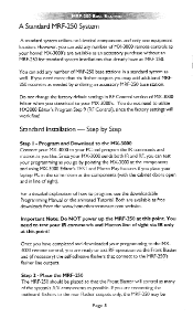
The flashers plug in every direction, so you to the MRF-250 throughout your house (50-100' away, indoors or outdoors). The MX-3000 remote control sends radio waves in to point the remote anymore! 2. The Flashers relay commands to the Infrared sensors...MRF-250's built-in the same cabinet space as the MRF-250. 3. The MRF-250 converts your house. Introduction The combination of the MX-3000 with it's companion MRF-250 base station will enable you don't have to the MRF-250's rear flasher line outputs via their 10 foot cables. The MX3000 sends radio signals to place your audio/video...
The flashers plug in every direction, so you to the MRF-250 throughout your house (50-100' away, indoors or outdoors). The MX-3000 remote control sends radio waves in to point the remote anymore! 2. The Flashers relay commands to the Infrared sensors...MRF-250's built-in the same cabinet space as the MRF-250. 3. The MRF-250 converts your house. Introduction The combination of the MX-3000 with it's companion MRF-250 base station will enable you don't have to the MRF-250's rear flasher line outputs via their 10 foot cables. The MX3000 sends radio signals to place your audio/video...

Owners Manual
Page 5
... additional MRF-250's can be programmed to operate equipment placed throughout the house, by installing an MRF-250 base station at any direction. MRF-250 Receiver with 10 foot plug in another room! Flashers with integrated antenna I - 9V-300mA Power Supply 6 - Reliable Control Throughout Your House The MRF-250 receives RF signals from your MX-3000 from any of your AN components. Page 2 Features and Benefits No More Pointing - No Pointing Remote Controls...
... additional MRF-250's can be programmed to operate equipment placed throughout the house, by installing an MRF-250 base station at any direction. MRF-250 Receiver with 10 foot plug in another room! Flashers with integrated antenna I - 9V-300mA Power Supply 6 - Reliable Control Throughout Your House The MRF-250 receives RF signals from your MX-3000 from any of your AN components. Page 2 Features and Benefits No More Pointing - No Pointing Remote Controls...

Owners Manual
Page 6
The MRF-250 Mounting Plate Using the four enclosed screws, you can choose to fix the mounting plate to all AN components in the same cabinet space. Page 3 The MRF-250's slots enable the Mounting Plate's matching guides to slide and "snap" into an active AC outlet. Red STATUS LED lights when the MRF-250 receives an RF signal from the MX-3000. Front Blaster sends infrared commands to a wall or the back of your component cabinet. MRF-250 Details Red POWER LED lights when the MRF-250's power supply is plugged into place for mounting on the wall.
The MRF-250 Mounting Plate Using the four enclosed screws, you can choose to fix the mounting plate to all AN components in the same cabinet space. Page 3 The MRF-250's slots enable the Mounting Plate's matching guides to slide and "snap" into an active AC outlet. Red STATUS LED lights when the MRF-250 receives an RF signal from the MX-3000. Front Blaster sends infrared commands to a wall or the back of your component cabinet. MRF-250 Details Red POWER LED lights when the MRF-250's power supply is plugged into place for mounting on the wall.

Owners Manual
Page 7
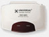
Bottom panel Dial sets the Receiver ID# when more than one MRF-250 receiver is used. Six Rear Flasher Line Output Jacks connect flashers for control of A/V components out of sight of the MRF250's Front Blaster. Six Plug-In Flashers are supplied with 10 foot cables and six extra self-adhesive pads (in any direction to be repositioned). Included 9V power supply plugs into the MRF-250's power connector. Page 4 I, I MRF-250 BASE STATION gen Integrated Antenna swings in case a flasher has to optimize RF reception and range.
Bottom panel Dial sets the Receiver ID# when more than one MRF-250 receiver is used. Six Rear Flasher Line Output Jacks connect flashers for control of A/V components out of sight of the MRF250's Front Blaster. Six Plug-In Flashers are supplied with 10 foot cables and six extra self-adhesive pads (in any direction to be repositioned). Included 9V power supply plugs into the MRF-250's power connector. Page 4 I, I MRF-250 BASE STATION gen Integrated Antenna swings in case a flasher has to optimize RF reception and range.
Owners Manual
Page 8
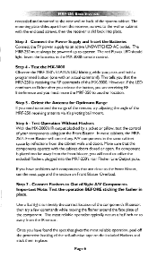
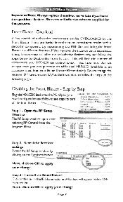
... free downloads from the www.hometheatermaster.com website. However, you download to the rear Flasher outputs only, the MRF-250 may add additional MRF250 receivers as needed by ordering an accessory MRF-250 base station. Important Note: Do NOT power up the MRF-250 at this point! You do not need to test your IR commands and Macros line of MX-3000 remote controls to the MRF-250's flasher line outputs...
... free downloads from the www.hometheatermaster.com website. However, you download to the rear Flasher outputs only, the MRF-250 may add additional MRF250 receivers as needed by ordering an accessory MRF-250 base station. Important Note: Do NOT power up the MRF-250 at this point! You do not need to test your IR commands and Macros line of MX-3000 remote controls to the MRF-250's flasher line outputs...
Owners Manual
Page 9
... the operation BEFORE sticking the flasher in place. concealed and mounted to the rear wall or back of the MRF-250 receiving antenna via it's pivoting ball mount. Test the MX-3000 Observe the MRF-250's STATUS LED blinking while you will control any AN components in the MX-3000 remote control. Step 7 - The red POWER LED should light. Step 3 - Connect Flashers to utilize the included Flashers plugged...
... the operation BEFORE sticking the flasher in place. concealed and mounted to the rear wall or back of the MRF-250 receiving antenna via it's pivoting ball mount. Test the MX-3000 Observe the MRF-250's STATUS LED blinking while you will control any AN components in the MX-3000 remote control. Step 7 - The red POWER LED should light. Step 3 - Connect Flashers to utilize the included Flashers plugged...
Owners Manual
Page 10
... an additional MRF-250 (available as the first unit) then follow these steps to turn off the Front Blaster Click on OK to apply your change. Select OFF from the Program Menu. If this purpose. Al Default Al IR A F Default Al TA IRfl r Default Al Default Al TV Ddrailt Al VC ofeule lit KIE- A list box will limit the number of audio/video components can...
... an additional MRF-250 (available as the first unit) then follow these steps to turn off the Front Blaster Click on OK to apply your change. Select OFF from the Program Menu. If this purpose. Al Default Al IR A F Default Al TA IRfl r Default Al Default Al TV Ddrailt Al VC ofeule lit KIE- A list box will limit the number of audio/video components can...
Owners Manual
Page 11
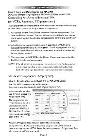
... six identical TV's are installing an MRF-250 to the MX-3000. Program One Device With IR commands. Using either the IR Database or Learning, program one device for each other the Flashers and the actual sensor window of the component should be blocked with black electrical tape (sometimes more ... changes using FilelSave and DOWNLOAD to control an array of TV's (leave the others powered off right now). Each identical component must note the NUMBER of your identical TV's. NOTE: If the identical components are near each of the identical components to the MX-3000 SAVE your work....
... six identical TV's are installing an MRF-250 to the MX-3000. Program One Device With IR commands. Using either the IR Database or Learning, program one device for each other the Flashers and the actual sensor window of the component should be blocked with black electrical tape (sometimes more ... changes using FilelSave and DOWNLOAD to control an array of TV's (leave the others powered off right now). Each identical component must note the NUMBER of your identical TV's. NOTE: If the identical components are near each of the identical components to the MX-3000 SAVE your work....

Owners Manual
Page 12
... RF Setup window opens after selecting RF Control from the three options shown in the pull down list box . Additionally, if you are not using it, you can see that the default sends IR commands for Flashers, you may wish to adjust the Signal output by clicking on the device you to disable the Front Blaster (see that the factory default programming sets...
... RF Setup window opens after selecting RF Control from the three options shown in the pull down list box . Additionally, if you are not using it, you can see that the default sends IR commands for Flashers, you may wish to adjust the Signal output by clicking on the device you to disable the Front Blaster (see that the factory default programming sets...

Owners Manual
Page 13
...other components of the system set to it. Finally, download to ALL. Default Default Default. You may leave the other components of the system set to your work. Step 8 - When you to your identical TV's! Likewise for the rest of your connection notes) for the first ...output by the MX-3000 for each device individually, by clicking on the "cell" for EACH of the identical TV's. Adjust the Flashers For Each of the Identical Devices The RF Setup window enables you select TV I TV 4 Signal IFI & RF IR & RF IR & RF IR & RF IR & FL R= Rece,k,ei. Click on the OK button...
...other components of the system set to it. Finally, download to ALL. Default Default Default. You may leave the other components of the system set to your work. Step 8 - When you to your identical TV's! Likewise for the rest of your connection notes) for the first ...output by the MX-3000 for each device individually, by clicking on the "cell" for EACH of the identical TV's. Adjust the Flashers For Each of the Identical Devices The RF Setup window enables you select TV I TV 4 Signal IFI & RF IR & RF IR & RF IR & RF IR & FL R= Rece,k,ei. Click on the OK button...

Owners Manual
Page 14
... the Receiver settings Extend the RF Setup window by assigning each with an MRF-250 assigned a unique Receiver ID#. Step 3 - Delete receivers by selecting them for the Receivers Name Default Recs.jyei ID IR LED Output -I :Lon-municationg. Cancel Step 4 - Save and Download to a receiver. I - In 0 OFF da Ren.5-Re Add new receivers by clicking on the Receivers button of the RF setup window. Deiete. on the • Add button. Programming...
... the Receiver settings Extend the RF Setup window by assigning each with an MRF-250 assigned a unique Receiver ID#. Step 3 - Delete receivers by selecting them for the Receivers Name Default Recs.jyei ID IR LED Output -I :Lon-municationg. Cancel Step 4 - Save and Download to a receiver. I - In 0 OFF da Ren.5-Re Add new receivers by clicking on the Receivers button of the RF setup window. Deiete. on the • Add button. Programming...

Owners Manual
Page 15
... the MRF-250 directly adjacent to the MRF-250? Frequently Asked Questions Can I use flasher/emitters that I have already installed in the system to connect to satellite receivers, personal computers or any manufacturers defects or workmanship for a period of one of them, the TV next to fit the MRF-250's flasher jacks. Specifications MRF-250 Power Supply: 9V 300mA IR Flasher Line Outputs: 2.5mm Mono Mini Jack RE Frequency: 418MHz Size...
... the MRF-250 directly adjacent to the MRF-250? Frequently Asked Questions Can I use flasher/emitters that I have already installed in the system to connect to satellite receivers, personal computers or any manufacturers defects or workmanship for a period of one of them, the TV next to fit the MRF-250's flasher jacks. Specifications MRF-250 Power Supply: 9V 300mA IR Flasher Line Outputs: 2.5mm Mono Mini Jack RE Frequency: 418MHz Size...

