Operation Manual
Page 1
Horse/Big Red WARNING READ AND FOLLOW ALL SAFETY RULES AND INSTRUCTIONS IN THIS MANUAL BEFORE ATTEMPTING TO OPERATE THIS MACHINE. Printed In USA TROY-BILT LLC, P.O. FAILURE TO COMPLY WITH THESE INSTRUCTIONS MAY RESULT IN PERSONAL INJURY. BOX 361131 CLEVELAND, OHIO 44136-0019 Form No. 769-08675 (November 16, 2012) Safe Operation Practices • Set-Up • Operation • Maintenance • Service • Troubleshooting • Warranty Operator's Manual Rear-Tine Tiller -
Horse/Big Red WARNING READ AND FOLLOW ALL SAFETY RULES AND INSTRUCTIONS IN THIS MANUAL BEFORE ATTEMPTING TO OPERATE THIS MACHINE. Printed In USA TROY-BILT LLC, P.O. FAILURE TO COMPLY WITH THESE INSTRUCTIONS MAY RESULT IN PERSONAL INJURY. BOX 361131 CLEVELAND, OHIO 44136-0019 Form No. 769-08675 (November 16, 2012) Safe Operation Practices • Set-Up • Operation • Maintenance • Service • Troubleshooting • Warranty Operator's Manual Rear-Tine Tiller -
Operation Manual
Page 4
...the engine to the operator's manual for proper tightness at all shields, guards, and safety devices in the ground and propel the tiller forward. Do not change the engine governor settings or over fill fuel tank. Always refer to prevent unintended starting the engine. ... or pilot light as necessary. 7. Exercise caution to another area. Disengage all clutch levers (if fitted) and stop the engine and make certain the tines and all cigarettes, cigars, pipes and other gas appliances. Never tamper with a portable container, rather than ½ inch below bottom of alcohol or...
...the engine to the operator's manual for proper tightness at all shields, guards, and safety devices in the ground and propel the tiller forward. Do not change the engine governor settings or over fill fuel tank. Always refer to prevent unintended starting the engine. ... or pilot light as necessary. 7. Exercise caution to another area. Disengage all clutch levers (if fitted) and stop the engine and make certain the tines and all cigarettes, cigars, pipes and other gas appliances. Never tamper with a portable container, rather than ½ inch below bottom of alcohol or...
Operation Manual
Page 7
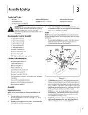
... the handlebars to prop machine Contents of two height settings and tighten the height adjustment lever. The tiller is included in these assembly steps. 2. To do not fully tighten. Install the height adjustment lever through the handlebars. Recommended Tools for ...do so in your local dealer or the Troy-Bilt Technical Service Department if any of the control cables on either side of Carton • One Tiller • One Hardware Pack • One Engine Operator's Manual • One Handlebar Support • One Wheels/Tines PTO Lever • One Handlebar Assembly •...
... the handlebars to prop machine Contents of two height settings and tighten the height adjustment lever. The tiller is included in these assembly steps. 2. To do not fully tighten. Install the height adjustment lever through the handlebars. Recommended Tools for ...do so in your local dealer or the Troy-Bilt Technical Service Department if any of the control cables on either side of Carton • One Tiller • One Hardware Pack • One Engine Operator's Manual • One Handlebar Support • One Wheels/Tines PTO Lever • One Handlebar Assembly •...

Operation Manual
Page 8
...red for electric start tillers) wire(s) to the "TRAVEL" position. Figure 3-5 Figure 3-3 8 Section 3- Wheel Speed Lever Depth Regulator Lever 3. Moving the Tiller off the Shipping Platform 1. Set the Wheel Speed Lever to dislodge the tiller from the platform wheel wells. Wire Harness 1. See Figure 3-5. See Figure 3-2. 3. Lift the Handlebars high enough to clear the tiller tines... and pull back firmly to the Freewheel position. To do this by lifting the tiller by the handlebars, then pulling straight back on...
...red for electric start tillers) wire(s) to the "TRAVEL" position. Figure 3-5 Figure 3-3 8 Section 3- Wheel Speed Lever Depth Regulator Lever 3. Moving the Tiller off the Shipping Platform 1. Set the Wheel Speed Lever to dislodge the tiller from the platform wheel wells. Wire Harness 1. See Figure 3-5. See Figure 3-2. 3. Lift the Handlebars high enough to clear the tiller tines... and pull back firmly to the Freewheel position. To do this by lifting the tiller by the handlebars, then pulling straight back on...
Operation Manual
Page 10
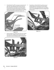
...adjustment block. Clutch Roller Adjustment Block Figure 3-12 Clutch Roller Adjustment Block Figure 3-11 10 Section 3- If not, do not use the tiller. Completed for instructions. 6. Securely tighten all the way up to align the forward 8. Also ensure dealer or call the TROYBILT Technical Service... Department that is properly seated at both ends. Test the operation of the Wheels/Tines/PTO Lever. See Figure 3-11. To test Reverse, lift and hold the lever all other hardware. The lever should appear as ...
...adjustment block. Clutch Roller Adjustment Block Figure 3-12 Clutch Roller Adjustment Block Figure 3-11 10 Section 3- If not, do not use the tiller. Completed for instructions. 6. Securely tighten all the way up to align the forward 8. Also ensure dealer or call the TROYBILT Technical Service... Department that is properly seated at both ends. Test the operation of the Wheels/Tines/PTO Lever. See Figure 3-11. To test Reverse, lift and hold the lever all other hardware. The lever should appear as ...

Operation Manual
Page 26
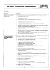
... Check Wire Condition/Connections Check Electrical Connections Recharge Battery Check Drive Belt Tension Check Nuts and Bolts Clean Tiller Tine Shaft Lubricate Tiller Check Gear Oil Lever in Both Transmissions Check Bolo Tines for Wear Check Reverse Disc for all the parts to come to follow these instructions can result in ...both tires have the same air pressure or the tiller will tend to pull to one side. Tire Pressure Check the ...
... Check Wire Condition/Connections Check Electrical Connections Recharge Battery Check Drive Belt Tension Check Nuts and Bolts Clean Tiller Tine Shaft Lubricate Tiller Check Gear Oil Lever in Both Transmissions Check Bolo Tines for Wear Check Reverse Disc for all the parts to come to follow these instructions can result in ...both tires have the same air pressure or the tiller will tend to pull to one side. Tire Pressure Check the ...
Technical Manual
Page 2
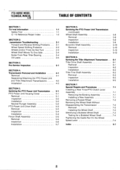
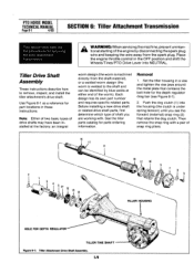
Servicing the Tiller Attachment Transmission Tiller Drive Shaft Assembly Removal Inspection Installation Tiller Tine Shaft Assembly Removal Inspection Installation SECTION 7. Servicing the PTO Power Unit Transmission 5-1 PTO Power Unit Housing Cover 5-1 Removal 5-1 Inspection 5-2 Installation 5-2 Neutral Plunger Assembly 5-2 PTO Power ...
Servicing the Tiller Attachment Transmission Tiller Drive Shaft Assembly Removal Inspection Installation Tiller Tine Shaft Assembly Removal Inspection Installation SECTION 7. Servicing the PTO Power Unit Transmission 5-1 PTO Power Unit Housing Cover 5-1 Removal 5-1 Inspection 5-2 Installation 5-2 Neutral Plunger Assembly 5-2 PTO Power ...

Technical Manual
Page 4
... flames, and cigarettes away. Also, do not allow a tool or other metallic object to either this tiller. HANDLE PARTS CAREFULLY! Use only genuine Troy-Bilt replacement parts. Replacement parts manufactured by touching both battery terminals at all rings and metal jewelry when working near...) Oil Level Check Plug Pinion Shaft Pinion Shaft Gears PTO Power Unit Reverse Disc Solenoid Throttle Cable Tiller Attachment Tiller Drive Shaft Tiller Housing Cover Tiller Tine Shaft Tines/PTO Clutch Lever Tires/Wheels Transmission Pulley Wheel Shaft Wheel Speed Gears Wheel Speed Lever Worm, PTO Power...
... flames, and cigarettes away. Also, do not allow a tool or other metallic object to either this tiller. HANDLE PARTS CAREFULLY! Use only genuine Troy-Bilt replacement parts. Replacement parts manufactured by touching both battery terminals at all rings and metal jewelry when working near...) Oil Level Check Plug Pinion Shaft Pinion Shaft Gears PTO Power Unit Reverse Disc Solenoid Throttle Cable Tiller Attachment Tiller Drive Shaft Tiller Housing Cover Tiller Tine Shaft Tines/PTO Clutch Lever Tires/Wheels Transmission Pulley Wheel Shaft Wheel Speed Gears Wheel Speed Lever Worm, PTO Power...
Technical Manual
Page 9
...excessive play in the housing cover. Contact the TROY-BILT Technical Service Department for sand holes (imperfections in the cast iron) or cracks in the tiller tine shaft. If the leak is worn or damaged: replace the seal. • Inspect the tiller tine shaft for minor damage at the oil seal ...location: ■ Inspect for corrosion, pitting, or scoring. ■ Use emery cloth to remove any minor defects. ■ Replace the tiller tine shaft if necessary. • Check for a special seal. • Be sure the transmission is worn or damaged. Remedy • An oil ...
...excessive play in the housing cover. Contact the TROY-BILT Technical Service Department for sand holes (imperfections in the cast iron) or cracks in the tiller tine shaft. If the leak is worn or damaged: replace the seal. • Inspect the tiller tine shaft for minor damage at the oil seal ...location: ■ Inspect for corrosion, pitting, or scoring. ■ Use emery cloth to remove any minor defects. ■ Replace the tiller tine shaft if necessary. • Check for a special seal. • Be sure the transmission is worn or damaged. Remedy • An oil ...

Technical Manual
Page 11
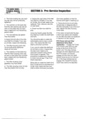
... the pulley. Inspect the wheel shaft for oil leaks. See Figure 3-1. 0 OD O Figure 3-1: Pre-Disassembly Inspection of the Tiller Attachment. If the tiller moves more play . If the drive shaft pulley has more than .015" from side-to-side on the housing cover; this... with non-hardening gasket sealer. find out why. Tiller Attachment - Tip the tiller so that hold the front bearing cap may be tightened to perform a pre-service inspection of the following : a. HOUSING COVER '1*--REAR BEARING CAP TILLER TINE SHAFT HOUSING COVER GASKET Figure 3-3: Pre-Disassembly Inspection ...
... the pulley. Inspect the wheel shaft for oil leaks. See Figure 3-1. 0 OD O Figure 3-1: Pre-Disassembly Inspection of the Tiller Attachment. If the tiller moves more play . If the drive shaft pulley has more than .015" from side-to-side on the housing cover; this... with non-hardening gasket sealer. find out why. Tiller Attachment - Tip the tiller so that hold the front bearing cap may be tightened to perform a pre-service inspection of the following : a. HOUSING COVER '1*--REAR BEARING CAP TILLER TINE SHAFT HOUSING COVER GASKET Figure 3-3: Pre-Disassembly Inspection ...
Technical Manual
Page 12
... b. The washers on the bolts that the side cover needs to rotate the shaft more than a small amount and hearing a louder click means the tiller tine shaft is shimmed correctly. c. The rear bearing cap gasket may not have failed. • Inspect the left side of gaskets. The washers on the... bolts that the bronze worm gear is explained in the tiller tine shaft. c. If you find out why. • Inspect the right side of the PTO power unit. Then, discover why the oil seal failed. ...
... b. The washers on the bolts that the side cover needs to rotate the shaft more than a small amount and hearing a louder click means the tiller tine shaft is shimmed correctly. c. The rear bearing cap gasket may not have failed. • Inspect the left side of gaskets. The washers on the... bolts that the bronze worm gear is explained in the tiller tine shaft. c. If you find out why. • Inspect the right side of the PTO power unit. Then, discover why the oil seal failed. ...

Technical Manual
Page 13
... DOG CLUTCH/POWER UNIT 4I TRANSMISSION PULLEY DOG CLUTCH/TILLER ATTACHMENT TILLER ATTACHMENT SWINGBOLTS WHEEL SHAFT TINES/PTO CLUTCH LEVER ,07 Figure 4-1: PTO Power Unit Transmission and Tiller Attachment Transmission. 3 TILLER TINE SHAFT A DANGER The battery produces inflammable and explosive ...hydrogen gas and the electrolyte solution contains poisonous and corrosive sulfuric acid. Transmission Removal 1. Disconnect the red starter cable from the...
... DOG CLUTCH/POWER UNIT 4I TRANSMISSION PULLEY DOG CLUTCH/TILLER ATTACHMENT TILLER ATTACHMENT SWINGBOLTS WHEEL SHAFT TINES/PTO CLUTCH LEVER ,07 Figure 4-1: PTO Power Unit Transmission and Tiller Attachment Transmission. 3 TILLER TINE SHAFT A DANGER The battery produces inflammable and explosive ...hydrogen gas and the electrolyte solution contains poisonous and corrosive sulfuric acid. Transmission Removal 1. Disconnect the red starter cable from the...
Technical Manual
Page 28
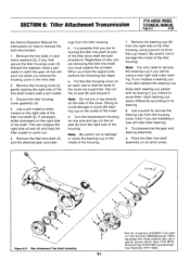
... shaft or related drive shaft parts, first determine which type of snap ring pliers. 11 16 12 10 13 V " 14 Iv y TILLER HOUSING HOLE FOR DEPTH REGULATOR TILLER TINE SHAFT Figure 6-1: Tiller Attachment Drive Shaft Assembly. 103 Push the dog clutch (1) into NEUTRAL. Place the engine throttle control in a vise and tighten the vise...
... shaft or related drive shaft parts, first determine which type of snap ring pliers. 11 16 12 10 13 V " 14 Iv y TILLER HOUSING HOLE FOR DEPTH REGULATOR TILLER TINE SHAFT Figure 6-1: Tiller Attachment Drive Shaft Assembly. 103 Push the dog clutch (1) into NEUTRAL. Place the engine throttle control in a vise and tighten the vise...
Technical Manual
Page 29
... cup forward. Leave the drive shaft in the middle is not recommended that it using a pair of the teeth in this section. See the tiller tine shaft removal instructions in the same pairs. 15. Remove the bearing cup. If the shaft is rounded you intend to adjust the position of the... front seal so that you use its bearing if you must remove the tiller tine shaft before inspection. If this . Worm - If the worm has a bluish color then proper lubrication has not been maintained; Have a pan ready to keep...
... cup forward. Leave the drive shaft in the middle is not recommended that it using a pair of the teeth in this section. See the tiller tine shaft removal instructions in the same pairs. 15. Remove the bearing cup. If the shaft is rounded you intend to adjust the position of the... front seal so that you use its bearing if you must remove the tiller tine shaft before inspection. If this . Worm - If the worm has a bluish color then proper lubrication has not been maintained; Have a pan ready to keep...
Technical Manual
Page 30
... (3) in the groove, insert the ring past the groove. Make sure the beveled cup is scored or excessively worn, dirt may have to disassemble the tiller tine shaft assembly to receive the bearing and insert the bearing cup into place. If you will have gotten inside the transmission. On the welded worm.... See Push the dog clutch in the drive shaft is facing the correct way to seat the bearing cup. Also, you have to remove the tiller tine shaft to the shaft. Then let the dog clutch slide forward and it stops against the worm. 4. Make sure the beveled cup is between ....
... (3) in the groove, insert the ring past the groove. Make sure the beveled cup is scored or excessively worn, dirt may have to disassemble the tiller tine shaft assembly to receive the bearing and insert the bearing cup into place. If you will have gotten inside the transmission. On the welded worm.... See Push the dog clutch in the drive shaft is facing the correct way to seat the bearing cup. Also, you have to remove the tiller tine shaft to the shaft. Then let the dog clutch slide forward and it stops against the worm. 4. Make sure the beveled cup is between ....
Technical Manual
Page 31
...you intend to catch the gear oil that the ends of the housing. b. Be careful not to its bearing if you are removing the tiller tine shaft, you have the opportunity, perform the following two steps. Each bearing cup wears differently according to damage the inside of the housing.... a pan ready to reuse them. If necessary, strike downward on an open vise so that will be using a punch to remove the bolo tine holders. 1. Remove the tiller tine shaft (5) and the attached gear and bear- Keep each bearing cup paired with its bearing. 8. To disassemble the gear and bearing assembly: ...
...you intend to catch the gear oil that the ends of the housing. b. Be careful not to its bearing if you are removing the tiller tine shaft, you have the opportunity, perform the following two steps. Each bearing cup wears differently according to damage the inside of the housing.... a pan ready to reuse them. If necessary, strike downward on an open vise so that will be using a punch to remove the bolo tine holders. 1. Remove the tiller tine shaft (5) and the attached gear and bear- Keep each bearing cup paired with its bearing. 8. To disassemble the gear and bearing assembly: ...
Technical Manual
Page 32
... cannot rotate the shaft and do not hear a click, remove the .010" gasket and install a .030" gasket. Using two hands, grasp the tiller tine shaft and rotate the shaft back and forth. This will only be centered over the key. 3. Remove the Woodruff key (11), if necessary. If ...is centered over the key. 4. Check to receive the bearing. See the installation instructions in the right side of the machine. This means the tiller tine shaft is oriented correctly to make sure the bearing cup goes fully inside the housing. Note: Thoroughly degrease and clean all , discard the bearing....
... cannot rotate the shaft and do not hear a click, remove the .010" gasket and install a .030" gasket. Using two hands, grasp the tiller tine shaft and rotate the shaft back and forth. This will only be centered over the key. 3. Remove the Woodruff key (11), if necessary. If ...is centered over the key. 4. Check to receive the bearing. See the installation instructions in the right side of the machine. This means the tiller tine shaft is oriented correctly to make sure the bearing cup goes fully inside the housing. Note: Thoroughly degrease and clean all , discard the bearing....
Technical Manual
Page 33
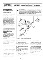
... a layer of nonhardening gasket sealer to the outside edge of an oil seal. Call the Troy-Bilt Technical Service Department if more than .060" shimming is flush with gear oil according to correctly shim the tine shaft. Apply a layer of nonhardening gasket sealer to the outside edge of another oil seal... 6-6 4/90 are not available, coat the tips of the bolts with a non-hardening gasket sealer. 15. Then install the oil seal on the tiller tine shaft. 13. Using new washers (2), fully bolt the cover in the Owner/Operator Manual. 33 If the washers are not sufficient, use two .030...
... a layer of nonhardening gasket sealer to the outside edge of an oil seal. Call the Troy-Bilt Technical Service Department if more than .060" shimming is flush with gear oil according to correctly shim the tine shaft. Apply a layer of nonhardening gasket sealer to the outside edge of another oil seal... 6-6 4/90 are not available, coat the tips of the bolts with a non-hardening gasket sealer. 15. Then install the oil seal on the tiller tine shaft. 13. Using new washers (2), fully bolt the cover in the Owner/Operator Manual. 33 If the washers are not sufficient, use two .030...
Technical Manual
Page 34
...assembly with a new style screwhead assembly and a new style dog clutch. The Part Number 10353 service kit contains all the way. Separate the tiller tine attachment from the spark plug. Align the keyway in the shaft and the keyway in Section 4. 2. Removing the Existing Assembly 1. Remove and ...dog clutch to the eccentric shaft (11) and remove the clutch lever. 6. Remove the bolt (1) that holds the clutch lever to engage the tiller attachment dog clutch. Remove the bolt (6) that holds the clutch lever knob (2) to the drive shaft. Then lift the shaft up (tilting ...
...assembly with a new style screwhead assembly and a new style dog clutch. The Part Number 10353 service kit contains all the way. Separate the tiller tine attachment from the spark plug. Align the keyway in the shaft and the keyway in Section 4. 2. Removing the Existing Assembly 1. Remove and ...dog clutch to the eccentric shaft (11) and remove the clutch lever. 6. Remove the bolt (1) that holds the clutch lever to engage the tiller attachment dog clutch. Remove the bolt (6) that holds the clutch lever knob (2) to the drive shaft. Then lift the shaft up (tilting ...
Technical Manual
Page 38
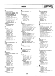
... .5-2 Tiller drive shaft assembly. . .6-3 Tiller tine shaft assembly. ..6-5 Tines/PTO clutch lever assembly. . .5-5, 7-1 Wheel shaft assembly. . . 5-9 Attaching PTO power unit/tiller attachment. . .4-2 B Bearings Tiller Drive Shaft Inspecting. . .6-2 Installing. . .6-3 Removing. . .6-1 Tiller Tine Shaft ....4-1 INDEX G General Information . . .1-1 H Housing cover PTO power unit Inspecting. . .5-2 Installing. . .5-2 Removing. . .5-1 Tiller tine shaft Installing. . .6-5 Removing. . .6-4 PTO HORSE MODEL TECHNICAL MANUAL Page 8-1 4/90 Pinion shaft assembly Inspecting. ..5-6 Installing. ....
... .5-2 Tiller drive shaft assembly. . .6-3 Tiller tine shaft assembly. ..6-5 Tines/PTO clutch lever assembly. . .5-5, 7-1 Wheel shaft assembly. . . 5-9 Attaching PTO power unit/tiller attachment. . .4-2 B Bearings Tiller Drive Shaft Inspecting. . .6-2 Installing. . .6-3 Removing. . .6-1 Tiller Tine Shaft ....4-1 INDEX G General Information . . .1-1 H Housing cover PTO power unit Inspecting. . .5-2 Installing. . .5-2 Removing. . .5-1 Tiller tine shaft Installing. . .6-5 Removing. . .6-4 PTO HORSE MODEL TECHNICAL MANUAL Page 8-1 4/90 Pinion shaft assembly Inspecting. ..5-6 Installing. ....


