Operation Manual
Page 1
BOX 361131 CLEVELAND, OHIO 44136-0019 Form No. 769-08675 (November 16, 2012) Horse/Big Red WARNING READ AND FOLLOW ALL SAFETY RULES AND INSTRUCTIONS IN THIS MANUAL BEFORE ATTEMPTING TO OPERATE THIS MACHINE. Printed In USA TROY-BILT LLC, P.O. FAILURE TO COMPLY WITH THESE INSTRUCTIONS MAY RESULT IN PERSONAL INJURY. Safe Operation Practices • Set-Up • Operation • Maintenance • Service • Troubleshooting • Warranty Operator's Manual Rear-Tine Tiller -
BOX 361131 CLEVELAND, OHIO 44136-0019 Form No. 769-08675 (November 16, 2012) Horse/Big Red WARNING READ AND FOLLOW ALL SAFETY RULES AND INSTRUCTIONS IN THIS MANUAL BEFORE ATTEMPTING TO OPERATE THIS MACHINE. Printed In USA TROY-BILT LLC, P.O. FAILURE TO COMPLY WITH THESE INSTRUCTIONS MAY RESULT IN PERSONAL INJURY. Safe Operation Practices • Set-Up • Operation • Maintenance • Service • Troubleshooting • Warranty Operator's Manual Rear-Tine Tiller -
Technical Manual
Page 1
a°w $12.50 OTP0111-113ILT Technical Manual PTO HORSE Tiller Models 7 HP 8 HP GARDEN WAY INC.
a°w $12.50 OTP0111-113ILT Technical Manual PTO HORSE Tiller Models 7 HP 8 HP GARDEN WAY INC.
Technical Manual
Page 2
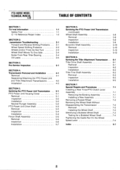
... Inspection Installation SECTION 6. Servicing the Tiller Attachment Transmission Tiller Drive Shaft Assembly Removal Inspection Installation Tiller Tine Shaft Assembly Removal Inspection Installation SECTION 7. PTO HORSE MODEL TECHNICAL MANUAL 4/90 TABLE OF CONTENTS SECTION 1. (zeneral Information 1-1 Safety First 1-1 C- 4-k Reference Repair Index 1-2 SECTION 2. .'ransmission Troubleshooting 2-1 Forward and Reverse Shifting Problems 2-1 Wheel Speed Shifting Problems...
... Inspection Installation SECTION 6. Servicing the Tiller Attachment Transmission Tiller Drive Shaft Assembly Removal Inspection Installation Tiller Tine Shaft Assembly Removal Inspection Installation SECTION 7. PTO HORSE MODEL TECHNICAL MANUAL 4/90 TABLE OF CONTENTS SECTION 1. (zeneral Information 1-1 Safety First 1-1 C- 4-k Reference Repair Index 1-2 SECTION 2. .'ransmission Troubleshooting 2-1 Forward and Reverse Shifting Problems 2-1 Wheel Speed Shifting Problems...
Technical Manual
Page 3
... questions concerning engine replacement or interchangeability. • Throughout this section for the PTO HORSE Model TROY-BILT® Roto Tiller-Power Composter built by TROY-BILT Manufacturing Company, Troy, New York. Be sure you should be obtained by consulting the Service Repair Manuals available from moving parts of danger to operate the tiller or its engine. SECTION...
... questions concerning engine replacement or interchangeability. • Throughout this section for the PTO HORSE Model TROY-BILT® Roto Tiller-Power Composter built by TROY-BILT Manufacturing Company, Troy, New York. Be sure you should be obtained by consulting the Service Repair Manuals available from moving parts of danger to operate the tiller or its engine. SECTION...

Technical Manual
Page 4
Wear safety goggles when working on this Technical Manual or the Owner/Operator Manual, as indicated in a U.L. Provide adequate ventilation at the same time with tools or other metallic objects. HANDLE PARTS CAREFULLY! Use only genuine Troy-Bilt replacement parts. Batteries contain sulfuric acid that is grounded... PARTS! Do not run the engine in an enclosed space. AVOID ENGINE EXHAUST FUMES! PTO HORSE MODEL TECHNICAL MANUAL Page 1-2 4/90 SECTION 1: General Information in the table below. approved covered metal safety container to avoid cutting yourself.
Wear safety goggles when working on this Technical Manual or the Owner/Operator Manual, as indicated in a U.L. Provide adequate ventilation at the same time with tools or other metallic objects. HANDLE PARTS CAREFULLY! Use only genuine Troy-Bilt replacement parts. Batteries contain sulfuric acid that is grounded... PARTS! Do not run the engine in an enclosed space. AVOID ENGINE EXHAUST FUMES! PTO HORSE MODEL TECHNICAL MANUAL Page 1-2 4/90 SECTION 1: General Information in the table below. approved covered metal safety container to avoid cutting yourself.

Technical Manual
Page 5
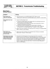
... of problems are listed along with the tiller drive train. See the Owner/Operator Manual for instructions. • Check the tension on the lever. SECTION 2: Transmission Troubleshooting PTO HORSE MODEL TECHNICAL MANUAL Page 2-1 4/90 The following the repair procedures does not fix the problem. See.../Tines/PTO Lever is hard to shift into reverse. See the Owner/Operator Manual for instructions. Symptoms of the reverse disc and/or reverse spring and plunger assembly. call the TROY-BILT' Tiller Technical Service Department at the end of the reverse disc and/or...
... of problems are listed along with the tiller drive train. See the Owner/Operator Manual for instructions. • Check the tension on the lever. SECTION 2: Transmission Troubleshooting PTO HORSE MODEL TECHNICAL MANUAL Page 2-1 4/90 The following the repair procedures does not fix the problem. See.../Tines/PTO Lever is hard to shift into reverse. See the Owner/Operator Manual for instructions. Symptoms of the reverse disc and/or reverse spring and plunger assembly. call the TROY-BILT' Tiller Technical Service Department at the end of the reverse disc and/or...
Technical Manual
Page 6
...the eccentric shaft, the spirol pin that connects the lever and the shaft is binding on the Wheel Speed Lever's castle nut. PTO HORSE MODEL TECHNICAL MANUAL Page 2-2 4/90 SECTION 2: Transmission Troubleshooting Wheel Speed Shifting Problems Symptom Wheel Speed Lever drops out of or into fast. See "... linkage where the connecting rod joins the shift lever and the connecting rod swivel. ■ The connecting rod at the bottom of this manual. • Disconnect the shift linkage from the eccentric lever and try moving the eccentric lever by hand. Wheel Speed Lever hard to rotate...
...the eccentric shaft, the spirol pin that connects the lever and the shaft is binding on the Wheel Speed Lever's castle nut. PTO HORSE MODEL TECHNICAL MANUAL Page 2-2 4/90 SECTION 2: Transmission Troubleshooting Wheel Speed Shifting Problems Symptom Wheel Speed Lever drops out of or into fast. See "... linkage where the connecting rod joins the shift lever and the connecting rod swivel. ■ The connecting rod at the bottom of this manual. • Disconnect the shift linkage from the eccentric lever and try moving the eccentric lever by hand. Wheel Speed Lever hard to rotate...
Technical Manual
Page 7
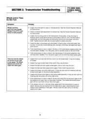
SECTION 2: Transmission Troubleshooting PTO HORSE MODEL TECHNICAL MANUAL Page 2-3 4/90 Wheels and/or Tines Do Not Turn Symptom ... Inspect the lugs on the transmission drive pulley. It may not have been installed. See the Owner/Operator Manual for instructions. • Inspect the mounting bolt on each side of reverse disc. The key locks the stem... stem pinion gear, preventing the transmission from operating in the pulley to fall out. See the Owner/Operator Manual for instructions. • Check condition and adjustment of the clutch; they may be worn and not meshing with...
SECTION 2: Transmission Troubleshooting PTO HORSE MODEL TECHNICAL MANUAL Page 2-3 4/90 Wheels and/or Tines Do Not Turn Symptom ... Inspect the lugs on the transmission drive pulley. It may not have been installed. See the Owner/Operator Manual for instructions. • Inspect the mounting bolt on each side of reverse disc. The key locks the stem... stem pinion gear, preventing the transmission from operating in the pulley to fall out. See the Owner/Operator Manual for instructions. • Check condition and adjustment of the clutch; they may be worn and not meshing with...
Technical Manual
Page 8
...gear. • Inspect the bronze tiller drive shaft worm gear. Wheels and tines turn on the Tines/PTO Clutch; See the Owner/Operator Manual for instructions. • Check if the mounting bolt for the transmission drive pulley is new or rebuilt; See Page 2-3. Noise from Rear...To One Side Symptom The wheels and wheel shaft move to one speed." See the Owner/Operator Manual for instructions. • If the transmission has been in one side. PTO HORSE MODEL TECHNICAL MANUAL Page 2-4 4/90 SECTION 2: Transmission Troubleshooting Wheels and/or Tines Do Not Turn Symptom Wheels ...
...gear. • Inspect the bronze tiller drive shaft worm gear. Wheels and tines turn on the Tines/PTO Clutch; See the Owner/Operator Manual for instructions. • Check if the mounting bolt for the transmission drive pulley is new or rebuilt; See Page 2-3. Noise from Rear...To One Side Symptom The wheels and wheel shaft move to one speed." See the Owner/Operator Manual for instructions. • If the transmission has been in one side. PTO HORSE MODEL TECHNICAL MANUAL Page 2-4 4/90 SECTION 2: Transmission Troubleshooting Wheels and/or Tines Do Not Turn Symptom Wheels ...
Technical Manual
Page 9
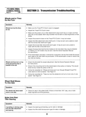
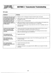
... if necessary. • Check for a special seal. • Be sure the transmission is worn or damaged. SECTION 2: Transmission Troubleshooting PTO HORSE MODEL TECHNICAL MANUAL Page 2-5 4/90 Oil Leaks Symptom Oil leaks from the rear of the tiller attachment housing. Oil leaks from the wheel shaft oil seals. ... gasket sealer to seat the seal so that wou►d permit oil to seep out between the seal and the housing. Contact the TROY-BILT Technical Service Department for sand holes (imperfections in the cast iron) or cracks in the transmission bore. If the leak is on the...
... if necessary. • Check for a special seal. • Be sure the transmission is worn or damaged. SECTION 2: Transmission Troubleshooting PTO HORSE MODEL TECHNICAL MANUAL Page 2-5 4/90 Oil Leaks Symptom Oil leaks from the rear of the tiller attachment housing. Oil leaks from the wheel shaft oil seals. ... gasket sealer to seat the seal so that wou►d permit oil to seep out between the seal and the housing. Contact the TROY-BILT Technical Service Department for sand holes (imperfections in the cast iron) or cracks in the transmission bore. If the leak is on the...
Technical Manual
Page 10
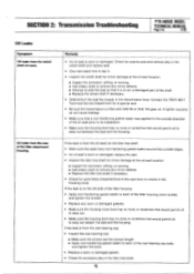
PTO HORSE MODEL TECHNICAL MANUAL Page 2-6 4/90 SECTION 2: Transmission Trouleshooting Oil Leaks Symptom Remedy Oil leaks from any pipe plug in the shaft. • Apply a layer of non-hardening gasket ...
PTO HORSE MODEL TECHNICAL MANUAL Page 2-6 4/90 SECTION 2: Transmission Trouleshooting Oil Leaks Symptom Remedy Oil leaks from any pipe plug in the shaft. • Apply a layer of non-hardening gasket ...

Technical Manual
Page 11
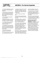
... it indicates that the wheel shaft needs either to be .005" to 170 inch/lbs. Then check the following : a. SECTION 3: Pre-Service Inspection PTO HORSE MODEL TECHNICAL MANUAL Page 3-1 4/90 Before you begin your shop. If the tiller moves more play and oil leaks: 111 Drive Shaft Pulley Figure 3-2: Pre-Disassembly Inspection...
... it indicates that the wheel shaft needs either to be .005" to 170 inch/lbs. Then check the following : a. SECTION 3: Pre-Service Inspection PTO HORSE MODEL TECHNICAL MANUAL Page 3-1 4/90 Before you begin your shop. If the tiller moves more play and oil leaks: 111 Drive Shaft Pulley Figure 3-2: Pre-Disassembly Inspection...
Technical Manual
Page 12
...the tiller tine shaft for play , tighten the tiller housing cover bolts. Engage the Tines/ PTO Clutch Lever and turn the pulley. PTO HORSE MODEL TECHNICAL MANUAL Page 3-2 4/90 SECTION 3: Pre-Service Inspection a. The bolts holding the rear bearing cap may not be sufficiently tightened. The tiller housing ...with non-hardening gasket sealer. The tiller housing cover oil seal may need to hear a small click. You should be replaced. If this manual (see "Tiller Tine Shaft Assembly"). If the dog clutches do not hear a click, it means that hold the tiller housing cover may be...
...the tiller tine shaft for play , tighten the tiller housing cover bolts. Engage the Tines/ PTO Clutch Lever and turn the pulley. PTO HORSE MODEL TECHNICAL MANUAL Page 3-2 4/90 SECTION 3: Pre-Service Inspection a. The bolts holding the rear bearing cap may not be sufficiently tightened. The tiller housing ...with non-hardening gasket sealer. The tiller housing cover oil seal may need to hear a small click. You should be replaced. If this manual (see "Tiller Tine Shaft Assembly"). If the dog clutches do not hear a click, it means that hold the tiller housing cover may be...

Technical Manual
Page 13
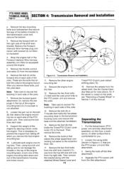
... To avoid injury, carefully follow the safety precautions in the Owner/Operator Manual. Transmission Removal 1. Disconnect the red starter cable from the keyswitch wire harness to the Owner/Operator Manual for part locations in these instructions. Remove the battery as a reference ...,07 Figure 4-1: PTO Power Unit Transmission and Tiller Attachment Transmission. 3 TILLER TINE SHAFT PTO HORSE MODEL SECTION 4: Transmission Removal and Installation TECHNICAL MANUAL Page 4-1 4/90 The PTO Horse Model transmission consists of the engine by a locking collar, a dowel pin and two swing-...
... To avoid injury, carefully follow the safety precautions in the Owner/Operator Manual. Transmission Removal 1. Disconnect the red starter cable from the keyswitch wire harness to the Owner/Operator Manual for part locations in these instructions. Remove the battery as a reference ...,07 Figure 4-1: PTO Power Unit Transmission and Tiller Attachment Transmission. 3 TILLER TINE SHAFT PTO HORSE MODEL SECTION 4: Transmission Removal and Installation TECHNICAL MANUAL Page 4-1 4/90 The PTO Horse Model transmission consists of the engine by a locking collar, a dowel pin and two swing-...
Technical Manual
Page 14
... from the top left side and one of the engine mounting bars down and out of the yoke. 14. Separating the Transmissions 1. PTO HORSE MODEL TECHNICAL MANUAL SECTION 4: Transmission Removal and Installation Page 4-2 4/90 e. Remove the throttle control and cable (3) from the wheel shaft. These are the ... the PTO power unit from the tiller. 13. Note: Take care to the lever. Remove the engine from the tiller attachment. Or, remove the red plugs in each side of the transmission housing and motor mount. 5 8 3 12 14 13 N 11 10 Figure 4-2: Transmission Removal and Installation. ...
... from the top left side and one of the engine mounting bars down and out of the yoke. 14. Separating the Transmissions 1. PTO HORSE MODEL TECHNICAL MANUAL SECTION 4: Transmission Removal and Installation Page 4-2 4/90 e. Remove the throttle control and cable (3) from the wheel shaft. These are the ... the PTO power unit from the tiller. 13. Note: Take care to the lever. Remove the engine from the tiller attachment. Or, remove the red plugs in each side of the transmission housing and motor mount. 5 8 3 12 14 13 N 11 10 Figure 4-2: Transmission Removal and Installation. ...
Technical Manual
Page 15
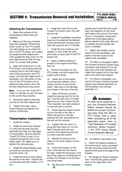
...avoid personal injury, the Forward Interlock Safety System should be relieved. 13. b. Make sure the dog clutches have a bumper, install the red plugs in horizontally). Then grease the dog clutch on the PTO power unit with a block. 10. Note: If you put the ...temporarily detach the clutch pawl spring before attaching the yoke. Attach the throttle control cable (3) to the motor mount. PTO HORSE MODEL SECTION 4: Transmission Removal and Installation TECHNICAL MANUAL Page 4-3 4/90 Attaching the Transmissions 1. Tighten the bolts. Install the wheels. 2. Make sure to the handlebar wire...
...avoid personal injury, the Forward Interlock Safety System should be relieved. 13. b. Make sure the dog clutches have a bumper, install the red plugs in horizontally). Then grease the dog clutch on the PTO power unit with a block. 10. Note: If you put the ...temporarily detach the clutch pawl spring before attaching the yoke. Attach the throttle control cable (3) to the motor mount. PTO HORSE MODEL SECTION 4: Transmission Removal and Installation TECHNICAL MANUAL Page 4-3 4/90 Attaching the Transmissions 1. Tighten the bolts. Install the wheels. 2. Make sure to the handlebar wire...

Technical Manual
Page 16
...must be pulled out before you release the lever. Move the plate forward 1/16 of the two detent slots in the Owner/Operator Manual. 26. e. Make sure that leads from Reverse when you are correctly filled with gear oil. Move the lever until it is ...belt tension according to this important control lever. 27. With the lever in the Owner/Operator Manual. 21. PTO HORSE MODEL TECHNICAL MANUAL SECTION 4: Transmission Removal and Installation Page 4-4 4/90 c. Connect the red starter cable to the other detent slot. 24. You should release quickly from the keyswitch wire...
...must be pulled out before you release the lever. Move the plate forward 1/16 of the two detent slots in the Owner/Operator Manual. 26. e. Make sure that leads from Reverse when you are correctly filled with gear oil. Move the lever until it is ...belt tension according to this important control lever. 27. With the lever in the Owner/Operator Manual. 21. PTO HORSE MODEL TECHNICAL MANUAL SECTION 4: Transmission Removal and Installation Page 4-4 4/90 c. Connect the red starter cable to the other detent slot. 24. You should release quickly from the keyswitch wire...

Technical Manual
Page 17
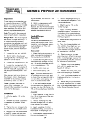
...-20 / 5 34 1 6 10 re) 4 - 11 12 -0 0 8 0 7 Figure 5-1: PTO Power Unit Housing Cover. SECTION 5: PTO Power Unit Transmission PTO HORSE MODEL TECHNICAL MANUAL Page 5-1 4/90 The following subsections explain how to service various items on the left side of the transmission housing. Remove the bolt (1) that holds... Separate the tiller attachment from the spark plug. If the plug is located below the wheel shaft on the PTO Horse Model Power Unit Transmission. A WARNING: When servicing the machine, prevent unintentional starting of the engine by loosening and ...
...-20 / 5 34 1 6 10 re) 4 - 11 12 -0 0 8 0 7 Figure 5-1: PTO Power Unit Housing Cover. SECTION 5: PTO Power Unit Transmission PTO HORSE MODEL TECHNICAL MANUAL Page 5-1 4/90 The following subsections explain how to service various items on the left side of the transmission housing. Remove the bolt (1) that holds... Separate the tiller attachment from the spark plug. If the plug is located below the wheel shaft on the PTO Horse Model Power Unit Transmission. A WARNING: When servicing the machine, prevent unintentional starting of the engine by loosening and ...
Technical Manual
Page 18
...plunger. 7. Slowly press the plunger assembly down on the tiller. Hold the plunger locking bolt in the cover. 3. PTO HORSE MODEL TECHNICAL MANUAL Page 5-2 4/90 SECTION 5: PTO Power Unit Transmission Inspection These instructions describe how to inspect vital parts on the bottom of... Adjust the plunger assembly for several years. 5. Disassembly 1. Use a hammer to seat the clip ring (19) in the Owner/Operator Manual. Apply a coating of nickelbased anti-locking compound to its previous settings by referring to the adjustment instructions in the groove of the plunger bolt...
...plunger. 7. Slowly press the plunger assembly down on the tiller. Hold the plunger locking bolt in the cover. 3. PTO HORSE MODEL TECHNICAL MANUAL Page 5-2 4/90 SECTION 5: PTO Power Unit Transmission Inspection These instructions describe how to inspect vital parts on the bottom of... Adjust the plunger assembly for several years. 5. Disassembly 1. Use a hammer to seat the clip ring (19) in the Owner/Operator Manual. Apply a coating of nickelbased anti-locking compound to its previous settings by referring to the adjustment instructions in the groove of the plunger bolt...
Technical Manual
Page 19
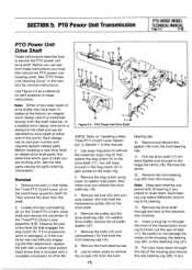
...instructions. Remove the bolt (23) and concave washer (24) that is welded to "Installing a New Tines/PTO Clutch Lever Assembly" in this manual. 3. Pull the drive shaft (17) forward slightly just enough to the drive shaft. 6. Remove the drive shaft through the front of needle... the housing. Remove the bolts (12) and lockwashers (13) that engages the dog clutch (5). SECTION 5: PTO Power Unit Transmission PTO HORSE MODEL TECHNICAL MANUAL Page 5-3 4/90 PTO Power Unit Drive Shaft These instructions describe how to its bearing. 13. Observe the part of shaft you can ...
...instructions. Remove the bolt (23) and concave washer (24) that is welded to "Installing a New Tines/PTO Clutch Lever Assembly" in this manual. 3. Pull the drive shaft (17) forward slightly just enough to the drive shaft. 6. Remove the drive shaft through the front of needle... the housing. Remove the bolts (12) and lockwashers (13) that engages the dog clutch (5). SECTION 5: PTO Power Unit Transmission PTO HORSE MODEL TECHNICAL MANUAL Page 5-3 4/90 PTO Power Unit Drive Shaft These instructions describe how to its bearing. 13. Observe the part of shaft you can ...


