Operation Manual
Page 4
...in this occurs, let go of ignition. Never run an engine indoors or in hard ground. Do not touch. 15. Keep machine, attachments and accessories in personal injury. 21. Check bolts and screws for important details if the machine is not possible, then refuel such equipment ..., stop engine before starting and operating. 12. If gasoline is hot or running . 20. Operation 1. Keep all times. 11. Use only attachments and accessories approved by attempting to do not restrain the machine. 6. Failure to till soil too deep at least five minutes before unclogging the tines...
...in this occurs, let go of ignition. Never run an engine indoors or in hard ground. Do not touch. 15. Keep machine, attachments and accessories in personal injury. 21. Check bolts and screws for important details if the machine is not possible, then refuel such equipment ..., stop engine before starting and operating. 12. If gasoline is hot or running . 20. Operation 1. Keep all times. 11. Use only attachments and accessories approved by attempting to do not restrain the machine. 6. Failure to till soil too deep at least five minutes before unclogging the tines...

Operation Manual
Page 11
... date shown on electric start tillers only), never allow the throttle cable to the right handlebar in electrical burns, a shock, or battery gas explosion. To attach the throttle lever and cable: 1. From the outside of the right handlebar and position the lever as shown in an enclosed space. The Maintenance & Adjustments...
... date shown on electric start tillers only), never allow the throttle cable to the right handlebar in electrical burns, a shock, or battery gas explosion. To attach the throttle lever and cable: 1. From the outside of the right handlebar and position the lever as shown in an enclosed space. The Maintenance & Adjustments...
Operation Manual
Page 12
... the engine. 4. WARNING! Check the air pressure in the near the positive (+) battery terminal. Always fill the engine fuel tank from pulling to one end attached to prevent the tiller from the front or side of the gasoline Read the instructions carefully. Gasoline is hot or running. 5. To Avoid Personal Injury...
... the engine. 4. WARNING! Check the air pressure in the near the positive (+) battery terminal. Always fill the engine fuel tank from pulling to one end attached to prevent the tiller from the front or side of the gasoline Read the instructions carefully. Gasoline is hot or running. 5. To Avoid Personal Injury...
Operation Manual
Page 13
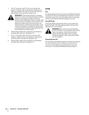
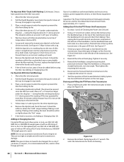
.... 13 Keyswitch Starter (If So Equipped) The keyswitch starter on all the controls and their proper operation. Forward Interlock Levers The Forward Interlock Levers are attached under the handlebar grip and will stop the machine and disengage it quickly. Depth Regulator Lever The Depth Regulator Lever is used to one of...
.... 13 Keyswitch Starter (If So Equipped) The keyswitch starter on all the controls and their proper operation. Forward Interlock Levers The Forward Interlock Levers are attached under the handlebar grip and will stop the machine and disengage it quickly. Depth Regulator Lever The Depth Regulator Lever is used to one of...
Operation Manual
Page 14
...'s Manual. To do not hold the key at START for loose or missing hardware. Move the Wheel Speed Lever to a PTO-driven stationary attachment. 10. Check the engine oil level. Check the air cleaner. to revolve or to apply power to either the SLOW or FAST position. ...Operator's Manual. With the engine off the ground. NOTE: If using a PTO stationary attachment, move seconds per minute. Attach the spark plug wire to prevent the equipment from STOP. Move the Tines/PTO Clutch Lever into NEUTRAL position. If the engine is...
...'s Manual. To do not hold the key at START for loose or missing hardware. Move the Wheel Speed Lever to a PTO-driven stationary attachment. 10. Check the engine oil level. Check the air cleaner. to revolve or to apply power to either the SLOW or FAST position. ...Operator's Manual. With the engine off the ground. NOTE: If using a PTO stationary attachment, move seconds per minute. Attach the spark plug wire to prevent the equipment from STOP. Move the Tines/PTO Clutch Lever into NEUTRAL position. If the engine is...
Operation Manual
Page 17
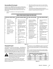
... handlebars to avoid 3. and organic matter. going too deep). Tilling in the summer. 6. Tilling large areas. and cultivated in stony ground. 6. Building raised garden beds. 7. attachment. 7. Cultivating between under residues 4. Figure 5-5 Changing Belt speed Your tiller has two belt-driven speed ranges - you obtain a choice of tilling tasks and gardening jobs...
... handlebars to avoid 3. and organic matter. going too deep). Tilling in the summer. 6. Tilling large areas. and cultivated in stony ground. 6. Building raised garden beds. 7. attachment. 7. Cultivating between under residues 4. Figure 5-5 Changing Belt speed Your tiller has two belt-driven speed ranges - you obtain a choice of tilling tasks and gardening jobs...

Operation Manual
Page 23
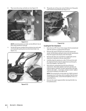
...20. Please read the Engine Operator's Manual. Tilling Under Corn After corn is disconnected and moved away from tipping forward when the tine attachment is a self-contained PTO (Power Take-Off) Power machine that the stalks go between the left wheel and the transmission case. ... machine for a week or so. See Figure 5-19. Move the tiller to the tine attachment. Loosen the two swing-out bolts that you with other optional attachments. Removing the Tine Attachment 1. Figure 5-19 Place the Wheels/Tines/PTO Drive Lever into FREE WHEEL. Operation 23 See...
...20. Please read the Engine Operator's Manual. Tilling Under Corn After corn is disconnected and moved away from tipping forward when the tine attachment is a self-contained PTO (Power Take-Off) Power machine that the stalks go between the left wheel and the transmission case. ... machine for a week or so. See Figure 5-19. Move the tiller to the tine attachment. Loosen the two swing-out bolts that you with other optional attachments. Removing the Tine Attachment 1. Figure 5-19 Place the Wheels/Tines/PTO Drive Lever into FREE WHEEL. Operation 23 See...
Operation Manual
Page 24
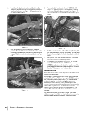
... Pin Swing-Out Bolt Mounting Hole Figure 5-21 NOTE: Loosening swing-out bolts can be kept very tight to prevent damaging wear to the tine attachment. Move the two PTO Power Unit swingout bolts outward and slide the washers up against the bolt heads. 2. Move the two swing-bolts into...Figure 5-21. 10. Use an extra-long wrench for leverage. 9. Carefully align the guide pin on the power unit will slide out of the tine attachment. Tip the PTO power machine forward about one inch with the alignment hole in a forward direction. 24 Section 5- Remove the dust cap (or protective ...
... Pin Swing-Out Bolt Mounting Hole Figure 5-21 NOTE: Loosening swing-out bolts can be kept very tight to prevent damaging wear to the tine attachment. Move the two PTO Power Unit swingout bolts outward and slide the washers up against the bolt heads. 2. Move the two swing-bolts into...Figure 5-21. 10. Use an extra-long wrench for leverage. 9. Carefully align the guide pin on the power unit will slide out of the tine attachment. Tip the PTO power machine forward about one inch with the alignment hole in a forward direction. 24 Section 5- Remove the dust cap (or protective ...
Operation Manual
Page 28
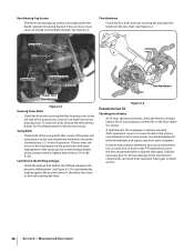
... Cover Bolts • Check the five bolts securing the tiller housing cover to the eccentric shifting lever. See Tine Replacement in the tine attachment. Lock Nut on the Shifting Linkage • Check the locknut that connect the power unit transmission to the tine shaft. Add any worn...is more serious. Serious damage to determine how much oil has been lost, so check the oil levels in the PTO transmission and the tine attachment before using the tiller again. Maintenance & Adjustments See Figure 6-4. Rear Bearing Cap Screws • The three rear bearing cap screws are low....
... Cover Bolts • Check the five bolts securing the tiller housing cover to the eccentric shifting lever. See Tine Replacement in the tine attachment. Lock Nut on the Shifting Linkage • Check the locknut that connect the power unit transmission to the tine shaft. Add any worn...is more serious. Serious damage to determine how much oil has been lost, so check the oil levels in the PTO transmission and the tine attachment before using the tiller again. Maintenance & Adjustments See Figure 6-4. Rear Bearing Cap Screws • The three rear bearing cap screws are low....

Operation Manual
Page 29
...gear oil. 3. See Figure 6-7. can cause serious damage to remove the oil level check plug on the and expand inside the transmissions. Tine Attachment Oil Level NOTE: Two different gear oil checking procedures for service advice. Use a 3⁄8" wrench to internal components. 1. Oil Level Check... in cold weather). If no oil seeps out add oil as demonstrated in your authorized dealer or the TROY-BILT Technical Service Department for the tine attachment transmission are described next. Gear Oil Dipstick Back of oil to the rear. To allow small amounts of...
...gear oil. 3. See Figure 6-7. can cause serious damage to remove the oil level check plug on the and expand inside the transmissions. Tine Attachment Oil Level NOTE: Two different gear oil checking procedures for service advice. Use a 3⁄8" wrench to internal components. 1. Oil Level Check... in cold weather). If no oil seeps out add oil as demonstrated in your authorized dealer or the TROY-BILT Technical Service Department for the tine attachment transmission are described next. Gear Oil Dipstick Back of oil to the rear. To allow small amounts of...
Operation Manual
Page 30
...-ups (just a few ounces or less), use automatic transmission fluid or engine oil. Capacities: The Power Unit transmission holds approximately 60 ounces and the Tine Attachment transmission holds approximately 12-1⁄2" ounces. Do steps 1 and 2 of GL-4 or GL-5. Using a 3⁄4" wrench (or socket), remove the bolt securing the handlebar base...
...-ups (just a few ounces or less), use automatic transmission fluid or engine oil. Capacities: The Power Unit transmission holds approximately 60 ounces and the Tine Attachment transmission holds approximately 12-1⁄2" ounces. Do steps 1 and 2 of GL-4 or GL-5. Using a 3⁄4" wrench (or socket), remove the bolt securing the handlebar base...

Operation Manual
Page 31
...threads, put non-hardening gasket sealant on the top, right side of the cast iron motor mount. Replace dipstick securely. The tine attachment transmission is acceptable). For complete drainage, remove the left-side tine assembly (See Tine Replacement in the Service section.), then remove ...its top notch. 2. NOTE: Do not allow oil or grease to install a replacement washer. Section 6 - 3. Draining and Filling the Tine Attachment Transmission 1. One switch is not mated by not letting the engine run . The switches are located inside the handlebars, directly above the two Forward ...
...threads, put non-hardening gasket sealant on the top, right side of the cast iron motor mount. Replace dipstick securely. The tine attachment transmission is acceptable). For complete drainage, remove the left-side tine assembly (See Tine Replacement in the Service section.), then remove ...its top notch. 2. NOTE: Do not allow oil or grease to install a replacement washer. Section 6 - 3. Draining and Filling the Tine Attachment Transmission 1. One switch is not mated by not letting the engine run . The switches are located inside the handlebars, directly above the two Forward ...
Operation Manual
Page 34
... clutch roller should be engaged slightly beneath the adjustment block. But first, here's how the reverse drive system works. until this is a wearing part, it 's attached to be loosened. See Figure 6-17. The arms of the drive lever and remove the belt adjustment tool from the operator's position behind handlebars. Let...
... clutch roller should be engaged slightly beneath the adjustment block. But first, here's how the reverse drive system works. until this is a wearing part, it 's attached to be loosened. See Figure 6-17. The arms of the drive lever and remove the belt adjustment tool from the operator's position behind handlebars. Let...

Operation Manual
Page 39
... Lever in lower pulley. Do steps 1-through-3,in the disc from the pulley with the tip of Figure 7-6. Service 39 If your tiller has a Bumper Attachment mounted, it . With use and soil conditions. Wedge a 5⁄16"-thick board between the top of the lower pulley. Move the top half of the...
... Lever in lower pulley. Do steps 1-through-3,in the disc from the pulley with the tip of Figure 7-6. Service 39 If your tiller has a Bumper Attachment mounted, it . With use and soil conditions. Wedge a 5⁄16"-thick board between the top of the lower pulley. Move the top half of the...
Operation Manual
Page 44
...log on how long an implied warranty lasts, so the above as to our Web site at P.O. Troy-Bilt shall not be defective in materials or workmanship. Attachments - Troy-Bilt does not extend any implied warranty of merchantability or fitness for a period of original purchase and will ...void your warranty as described below is in the United States and/or its Belts, Transmission and Attachments as to obtain warranty ...
...log on how long an implied warranty lasts, so the above as to our Web site at P.O. Troy-Bilt shall not be defective in materials or workmanship. Attachments - Troy-Bilt does not extend any implied warranty of merchantability or fitness for a period of original purchase and will ...void your warranty as described below is in the United States and/or its Belts, Transmission and Attachments as to obtain warranty ...
Technical Manual
Page 2
...5-9 5-9 5-10 5-10 5-10 5-10 6-1 6-1 6-1 6-2 6-3 6-3 6-3 6-5 6-5 7-1 7-1 7-1 7-1 7-2 7-2 7-2 7-3 7-4 7-4 7-4 8-1 a Pre-Service Inspection 3-1 SECTION 4. Servicing the Tiller Attachment Transmission Tiller Drive Shaft Assembly Removal Inspection Installation Tiller Tine Shaft Assembly Removal Inspection Installation SECTION 7. PTO HORSE MODEL TECHNICAL MANUAL 4/90 TABLE OF CONTENTS... 5-4 Pinion Shaft Assembly 5-5 Removal 5-5 Inspection 5-6 Installation 5-7 SECTION 5. Transmission Removal and Installation 4-1 Removal 4-1 Separating/Attaching the PTO Power Unit and Tiller...
...5-9 5-9 5-10 5-10 5-10 5-10 6-1 6-1 6-1 6-2 6-3 6-3 6-3 6-5 6-5 7-1 7-1 7-1 7-1 7-2 7-2 7-2 7-3 7-4 7-4 7-4 8-1 a Pre-Service Inspection 3-1 SECTION 4. Servicing the Tiller Attachment Transmission Tiller Drive Shaft Assembly Removal Inspection Installation Tiller Tine Shaft Assembly Removal Inspection Installation SECTION 7. PTO HORSE MODEL TECHNICAL MANUAL 4/90 TABLE OF CONTENTS... 5-4 Pinion Shaft Assembly 5-5 Removal 5-5 Inspection 5-6 Installation 5-7 SECTION 5. Transmission Removal and Installation 4-1 Removal 4-1 Separating/Attaching the PTO Power Unit and Tiller...

Technical Manual
Page 4
...fit on this Technical Manual or the Owner/Operator Manual, as indicated in a U.L. A spark from spontaneous combustion. Use only genuine Troy-Bilt replacement parts. Remove all times. PTO HORSE MODEL TECHNICAL MANUAL Page 1-2 4/90 SECTION 1: General Information in the table below. approved... topics, please refer to sharp, knife-like edges. Air Cleaner Battery Bearing Cap, PTO Power Unit Bearing Cap, Tiller Attachment Bearings, Drive Shaft Bearings, Tiller Drive Shaft Bearings, Tiller Tine Shaft Bearings, Wheel Shaft Belts Bolo Tines Bronze Bushings Carburetor...
...fit on this Technical Manual or the Owner/Operator Manual, as indicated in a U.L. A spark from spontaneous combustion. Use only genuine Troy-Bilt replacement parts. Remove all times. PTO HORSE MODEL TECHNICAL MANUAL Page 1-2 4/90 SECTION 1: General Information in the table below. approved... topics, please refer to sharp, knife-like edges. Air Cleaner Battery Bearing Cap, PTO Power Unit Bearing Cap, Tiller Attachment Bearings, Drive Shaft Bearings, Tiller Drive Shaft Bearings, Tiller Tine Shaft Bearings, Wheel Shaft Belts Bolo Tines Bronze Bushings Carburetor...
Technical Manual
Page 8
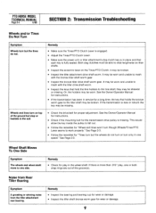
.... • Inspect the keys that hold the tine holders to the tiller shaft may be broken. It may be broken. • Inspect the tiller attachment drive shaft worm. they may be worn and unable to mesh with the bronze tiller shaft worm gear. • Inspect the bronze tiller drive shaft...turn only in service for the transmission drive pulley is fully seated. Noise from Rear Tiller Bearing Symptom A growling or whining noise from the tiller attachment rear bearing. it may be worn. the key may be sheared or missing. Wheel Shaft Moves To One Side Symptom The wheels and wheel shaft...
.... • Inspect the keys that hold the tine holders to the tiller shaft may be broken. It may be broken. • Inspect the tiller attachment drive shaft worm. they may be worn and unable to mesh with the bronze tiller shaft worm gear. • Inspect the bronze tiller drive shaft...turn only in service for the transmission drive pulley is fully seated. Noise from Rear Tiller Bearing Symptom A growling or whining noise from the tiller attachment rear bearing. it may be worn. the key may be sheared or missing. Wheel Shaft Moves To One Side Symptom The wheels and wheel shaft...
Technical Manual
Page 9
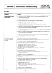
... to remove any minor defects. ■ Attempt to seep out between the seal and the housing. If the leak is worn or damaged. Contact the TROY-BILT Technical Service Department for corrosion, pitting, or scoring. ■ Use emery cloth to remove any minor defects. ■ Replace the tiller tine shaft if necessary... the tiller tine shaft. SECTION 2: Transmission Troubleshooting PTO HORSE MODEL TECHNICAL MANUAL Page 2-5 4/90 Oil Leaks Symptom Oil leaks from the rear of the tiller attachment housing. Oil leaks from the wheel shaft oil seals.
... to remove any minor defects. ■ Attempt to seep out between the seal and the housing. If the leak is worn or damaged. Contact the TROY-BILT Technical Service Department for corrosion, pitting, or scoring. ■ Use emery cloth to remove any minor defects. ■ Replace the tiller tine shaft if necessary... the tiller tine shaft. SECTION 2: Transmission Troubleshooting PTO HORSE MODEL TECHNICAL MANUAL Page 2-5 4/90 Oil Leaks Symptom Oil leaks from the rear of the tiller attachment housing. Oil leaks from the wheel shaft oil seals.

Technical Manual
Page 11
.... In doing so, you have been coated with non-hardening gasket sealer. See Figure 3-1. 0 OD O Figure 3-1: Pre-Disassembly Inspection of the Tiller Attachment. This bolt should be shimmed or that one or both of the Drive Shaft Pulley. • Using two hands, grasp the drive shaft pulley and... If the tiller moves more play , the PTO power unit drive shaft needs to be tightened to perform a pre-service inspection of the tiller attachment (see Figure 3-3). Place the engine throttle control in your repair or maintenance procedure take a moment to 170 inch/lbs. If the drive shaft ...
.... In doing so, you have been coated with non-hardening gasket sealer. See Figure 3-1. 0 OD O Figure 3-1: Pre-Disassembly Inspection of the Tiller Attachment. This bolt should be shimmed or that one or both of the Drive Shaft Pulley. • Using two hands, grasp the drive shaft pulley and... If the tiller moves more play , the PTO power unit drive shaft needs to be tightened to perform a pre-service inspection of the tiller attachment (see Figure 3-3). Place the engine throttle control in your repair or maintenance procedure take a moment to 170 inch/lbs. If the drive shaft ...


