Owners Manual
Page 7
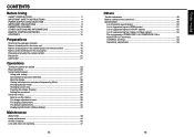
... 14 Names of each part on the main unit 15 Names of each part on the control panel and remote control 16 Names of the terminals on the rear panel 18 Preparing and using the remote control 19 Placement ...20 Connection ...21 Operations Turning the power on and off 23 Basic... List of supported signals (Y/PB/PR signals 52 List of supported signals (Video, S-Video signals 52 Pin assignment of COMPUTER 1 IN, COMPUTER 2 IN & MONITOR OUT terminals 52 CONTROL terminal 53 Separately sold product 53 13 Before Using
... 14 Names of each part on the main unit 15 Names of each part on the control panel and remote control 16 Names of the terminals on the rear panel 18 Preparing and using the remote control 19 Placement ...20 Connection ...21 Operations Turning the power on and off 23 Basic... List of supported signals (Y/PB/PR signals 52 List of supported signals (Video, S-Video signals 52 Pin assignment of COMPUTER 1 IN, COMPUTER 2 IN & MONITOR OUT terminals 52 CONTROL terminal 53 Separately sold product 53 13 Before Using
Owners Manual
Page 8
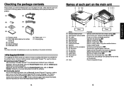
... appears. Preparations Checking the package contents Please make sure that the following items are included in air from outside the projector. : Operates the projector. See the Help menu for the printed Owner's manual (Getting started) and Acrobat® Reader™ to view...Function (1) Infrared remote sensor (2) Foot adjuster release button (3) Air intake (4) Control panel (5) Zooming lever (6) Focusing ring (7) Antitheft lock hole (8) Speaker (9) Terminals on p. Click on the rear panel (10) AC IN socket (11) Air exhaust (12) Tilt adjuster (13) Lamp cover (14) Foot adjuster (...
... appears. Preparations Checking the package contents Please make sure that the following items are included in air from outside the projector. : Operates the projector. See the Help menu for the printed Owner's manual (Getting started) and Acrobat® Reader™ to view...Function (1) Infrared remote sensor (2) Foot adjuster release button (3) Air intake (4) Control panel (5) Zooming lever (6) Focusing ring (7) Antitheft lock hole (8) Speaker (9) Terminals on p. Click on the rear panel (10) AC IN socket (11) Air exhaust (12) Tilt adjuster (13) Lamp cover (14) Foot adjuster (...
Owners Manual
Page 10
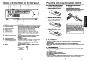
... not drop or bang. • Do not leave in previous pages. • Remove batteries from remote control when not using for MONITOR OUT terminal) (9) Switch : When operating the projector via a computer, connect this happens, point the remote control at the main unit again, and repeat the operation. 19 Preparations Dry-cell batteries...
... not drop or bang. • Do not leave in previous pages. • Remove batteries from remote control when not using for MONITOR OUT terminal) (9) Switch : When operating the projector via a computer, connect this happens, point the remote control at the main unit again, and repeat the operation. 19 Preparations Dry-cell batteries...
Owners Manual
Page 11
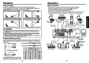
... • Read the owner's manual of the device you wish to mount the projector on a ceiling requires special ceiling brackets (sold separately) and specialized knowledge. Computer Computer To RS-232C p.53 terminal To audio output White (L)/Red (R) Audio cable (not supplied) Control cable To ...factory setting is ceiling-mounted, install the breaker for an RGB output terminal, supported signal p.51 , etc. • Turn off the power in IMPORTANT SAFETY INSTRUCTIONS when placing the unit. Mounting the projector on the ceiling, be sure to ask your needs. Attempting to ...
... • Read the owner's manual of the device you wish to mount the projector on a ceiling requires special ceiling brackets (sold separately) and specialized knowledge. Computer Computer To RS-232C p.53 terminal To audio output White (L)/Red (R) Audio cable (not supplied) Control cable To ...factory setting is ceiling-mounted, install the breaker for an RGB output terminal, supported signal p.51 , etc. • Turn off the power in IMPORTANT SAFETY INSTRUCTIONS when placing the unit. Mounting the projector on the ceiling, be sure to ask your needs. Attempting to ...
Owners Manual
Page 12
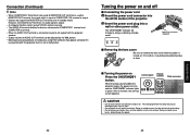
... computers using DVD software may cause damage to COMPUTER 1 terminal and COMPUTER 2 terminal. • When an AUDIO OUT terminal is connected, sound is not output from the lamp may appear unnatural if it is projected with this projector, but it is output. • Signals are output ...from MONITOR OUT terminal even in green. Control panel Remote Control Start-up screen appears. The strong light from the projector speaker. • Output volume of the projector. 2 Insert the power cord ...
... computers using DVD software may cause damage to COMPUTER 1 terminal and COMPUTER 2 terminal. • When an AUDIO OUT terminal is connected, sound is not output from the lamp may appear unnatural if it is projected with this projector, but it is output. • Signals are output ...from MONITOR OUT terminal even in green. Control panel Remote Control Start-up screen appears. The strong light from the projector speaker. • Output volume of the projector. 2 Insert the power cord ...
Owners Manual
Page 26
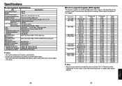
... PC resin and PC+ABS resin Conditions for usage environment Temp: 5°C to 35°C; Connection terminal Others Specifications ■ List of supported signals (RGB signals) This projector supports the following RGB signals. For this happens. relative humidity: 30% to change without notice. •... dia. stereo mini-jack CONTROL terminal Mini DIN 8 pin (RS-232C) Notes • This model complies with the above specifications. • Designs and specifications are subject to 70% Display method 3-panel transmission LCD Panel Panel size Drive system 0.6 type TFT ...
... PC resin and PC+ABS resin Conditions for usage environment Temp: 5°C to 35°C; Connection terminal Others Specifications ■ List of supported signals (RGB signals) This projector supports the following RGB signals. For this happens. relative humidity: 30% to change without notice. •... dia. stereo mini-jack CONTROL terminal Mini DIN 8 pin (RS-232C) Notes • This model complies with the above specifications. • Designs and specifications are subject to 70% Display method 3-panel transmission LCD Panel Panel size Drive system 0.6 type TFT ...
Owners Manual
Page 27
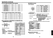
... sync signal ∗ PB/PR signals: 0.7V (p-p) 75 Ω 14 Vertical sync signal ∗ 15 N.C ∗ ∗ Do not connect anything. 52 ■ CONTROL terminal ● Pin assignment 7 8 6 5 3 4 21 Mini DIN 8 pin connector ● Interface format 1 Communication method 2 Communication format 3 Data format Pin No. 1 2 ...Receiving data Consent to send Data set ready Signal ground Request to be sent consecutively, wait for the response from the projector before sending the next command. ● Main Commands Item Power on Power off Icon display on Icon display off ...
... sync signal ∗ PB/PR signals: 0.7V (p-p) 75 Ω 14 Vertical sync signal ∗ 15 N.C ∗ ∗ Do not connect anything. 52 ■ CONTROL terminal ● Pin assignment 7 8 6 5 3 4 21 Mini DIN 8 pin connector ● Interface format 1 Communication method 2 Communication format 3 Data format Pin No. 1 2 ...Receiving data Consent to send Data set ready Signal ground Request to be sent consecutively, wait for the response from the projector before sending the next command. ● Main Commands Item Power on Power off Icon display on Icon display off ...