
Maintenance Manual
Page 4
... that could cause overheating, smoke or fire. ? Be sure to explode. iv Satellite A100/A105 / TECRA A7 Maintenance Manual WARNING: "Warning" indicates the existence of these messages will be sure to use only the same model battery or an equivalent battery recommended by Toshiba. CAUTION: "Caution" indicates the existence of a hazard that could result in...
... that could cause overheating, smoke or fire. ? Be sure to explode. iv Satellite A100/A105 / TECRA A7 Maintenance Manual WARNING: "Warning" indicates the existence of these messages will be sure to use only the same model battery or an equivalent battery recommended by Toshiba. CAUTION: "Caution" indicates the existence of a hazard that could result in...
Maintenance Manual
Page 7
... Battery 20 1.1.2 Battery Charging Control 20 1.1.3 RTC Battery 21 Chapter 2 Troubleshooting 2.1 Outline ...2-1 2.2 Basic Flowchart...2-2 2.3 Power Supply...2-6 Procedure 1 Power Icon Check 2-6 Procedure 2 Connection Check 2-8 Procedure 3 Replacement Check 2-8 2.4 System Board...2-9 Procedure 3 Replacement Check 2-10 2.5 2.5-inch HDD ...2-11 Procedure 1 Message Check 2-11 Procedure 2 Partition Check 2-11 Procedure 3 Format Check 2-12 Procedure 4 Test Program Check 2-13 Satellite A100/A105...
... Battery 20 1.1.2 Battery Charging Control 20 1.1.3 RTC Battery 21 Chapter 2 Troubleshooting 2.1 Outline ...2-1 2.2 Basic Flowchart...2-2 2.3 Power Supply...2-6 Procedure 1 Power Icon Check 2-6 Procedure 2 Connection Check 2-8 Procedure 3 Replacement Check 2-8 2.4 System Board...2-9 Procedure 3 Replacement Check 2-10 2.5 2.5-inch HDD ...2-11 Procedure 1 Message Check 2-11 Procedure 2 Partition Check 2-11 Procedure 3 Format Check 2-12 Procedure 4 Test Program Check 2-13 Satellite A100/A105...
Maintenance Manual
Page 11
... Procedures 4-5 Tools and Equipment 4-6 Screw Tightening Torque 4-6 Colors of Screw Shanks 4-7 Symbols of Screws on the Computer Body 4-7 Symbol examples 4-7 Removing the Battery Pack 4-8 Installing the Battery Pack 4-9 Removing the PCI Expresss Card 4-10 Installing the PCI Expresss Card 4-11 Removing the Optional PC Card 4-12 Installing the Optional PC Card...22 Installing the HDD 4-24 4.3 Speaker Cover and Keyboard 4-24 Removing the Speaker Cover and Keyboard 4-25 Installing the Speaker Cover and Keyboard 4-26 Satellite A100/A105 / TECRA A7 Maintenance Manual xi
... Procedures 4-5 Tools and Equipment 4-6 Screw Tightening Torque 4-6 Colors of Screw Shanks 4-7 Symbols of Screws on the Computer Body 4-7 Symbol examples 4-7 Removing the Battery Pack 4-8 Installing the Battery Pack 4-9 Removing the PCI Expresss Card 4-10 Installing the PCI Expresss Card 4-11 Removing the Optional PC Card 4-12 Installing the Optional PC Card...22 Installing the HDD 4-24 4.3 Speaker Cover and Keyboard 4-24 Removing the Speaker Cover and Keyboard 4-25 Installing the Speaker Cover and Keyboard 4-26 Satellite A100/A105 / TECRA A7 Maintenance Manual xi
Maintenance Manual
Page 17
1 Hardware Overview Chapter 1 Contents 1.1 Features...1 1.2 System Unit Components...9 1.3 2.5-inch HDD...15 1.4 DVD-ROM Drive...16 1.5 CD-RW/DVD-ROM Drive 17 1.6 DVD Super Multi (+-R Double Layer 18 1.7 Power Supply ...19 1.8 Batteries ...20 1.1.1 Main Battery 20 1.1.2 Battery Charging Control 20 1.1.3 RTC Battery 21 Satellite A100/A105 / TECRA A7 Maintenance Manual iii
1 Hardware Overview Chapter 1 Contents 1.1 Features...1 1.2 System Unit Components...9 1.3 2.5-inch HDD...15 1.4 DVD-ROM Drive...16 1.5 CD-RW/DVD-ROM Drive 17 1.6 DVD Super Multi (+-R Double Layer 18 1.7 Power Supply ...19 1.8 Batteries ...20 1.1.1 Main Battery 20 1.1.2 Battery Charging Control 20 1.1.3 RTC Battery 21 Satellite A100/A105 / TECRA A7 Maintenance Manual iii

Maintenance Manual
Page 18
... 15 Table 1- 2 DVD-ROM drive specifications 16 Table 1- 3 CD-RW/DVD-ROM drive specifications 17 Table 1- 4 DVD Super Multi drive (+-R Double Layer) specifications 18 Table 1- 5 Battery specifications 20 Table 1-6 Quick/normal charging time 21 iv Satellite A100/A105 / TECRA A7 Maintenance Manual
... 15 Table 1- 2 DVD-ROM drive specifications 16 Table 1- 3 CD-RW/DVD-ROM drive specifications 17 Table 1- 4 DVD Super Multi drive (+-R Double Layer) specifications 18 Table 1- 5 Battery specifications 20 Table 1-6 Quick/normal charging time 21 iv Satellite A100/A105 / TECRA A7 Maintenance Manual
Maintenance Manual
Page 19
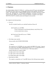
...16? 8P)/533/667 MHZ ? 1024 MB (64Mx16x8P)/533/667 MHZ ? The computer employs a Lithium Ion battery that the system can incorporate up to suit your memory requirements. Intel Yonah Processor (667MHz) T2300(1.66G)/T2400(1....Intel Yonah based Celeron M Processor (533MHz) 410/420/430 ? It can be battery-operated for your needs. 1.1 Features 1 Hardware Overview 1.1 Features The Toshiba Satellite A100/A105 / TECRA A7 is the Intel Yonah Processor and Intel Yonah based Celeron M. ... to 4 GB of the following storage capacities: Satellite A100/A105 / TECRA A7 Maintenance Manual 1
...16? 8P)/533/667 MHZ ? 1024 MB (64Mx16x8P)/533/667 MHZ ? The computer employs a Lithium Ion battery that the system can incorporate up to suit your memory requirements. Intel Yonah Processor (667MHz) T2300(1.66G)/T2400(1....Intel Yonah based Celeron M Processor (533MHz) 410/420/430 ? It can be battery-operated for your needs. 1.1 Features 1 Hardware Overview 1.1 Features The Toshiba Satellite A100/A105 / TECRA A7 is the Intel Yonah Processor and Intel Yonah based Celeron M. ... to 4 GB of the following storage capacities: Satellite A100/A105 / TECRA A7 Maintenance Manual 1
Maintenance Manual
Page 20
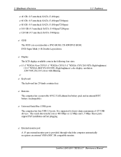
...four USB 2.0 ports, It is provided, through which the computer automatically recognizes an external VESA DDC 2B compatible monitor. 2 Satellite A100/A105 / TECRA A7 Maintenance Manual External monitor port A 15-pin external monitor port is supported to daisy-chain a maximum of ... ODD The ODD can accommodate a DVD-ROM, CD-RW/DVD ROM, DVD Super Multi (+-R Double Layer)drives. ? Batteries The computer has a removable 6/9/12 Cell Lithium Ion battery pack and an internal RTC battery (rechargeable). ? 1 Hardware Overview 1.1 Features ? 40 GB (9.5 mm thick) SATA (5,400rpm) ? 60 GB (9.5 ...
...four USB 2.0 ports, It is provided, through which the computer automatically recognizes an external VESA DDC 2B compatible monitor. 2 Satellite A100/A105 / TECRA A7 Maintenance Manual External monitor port A 15-pin external monitor port is supported to daisy-chain a maximum of ... ODD The ODD can accommodate a DVD-ROM, CD-RW/DVD ROM, DVD Super Multi (+-R Double Layer)drives. ? Batteries The computer has a removable 6/9/12 Cell Lithium Ion battery pack and an internal RTC battery (rechargeable). ? 1 Hardware Overview 1.1 Features ? 40 GB (9.5 mm thick) SATA (5,400rpm) ? 60 GB (9.5 ...
Maintenance Manual
Page 31
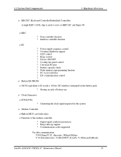
...? Digital signal conductor protection ? 1.2 System Unit Components 1 Hardware Overview ? EC ? LED control ? Beep control ? Battery capacity check ? Flash memory reprogramming function ? Battery EE PROM ? 24C02 equivalent (128 words x 16 bits, I2C interface) integrated in MDC card with askey ? Ring ...? Device ON/OFF ? Functions of battery use ? Communication codes supported: For data communication: V.90(China)/V.92 data rates: 28kbps/56kbps V.34 Extended rates: 33.6K/2400/V.32 turbo, V.32bits,and fallbacks Satellite A100/A105 / TECRA A7 Maintenance Manual 13 Modem...
...? Digital signal conductor protection ? 1.2 System Unit Components 1 Hardware Overview ? EC ? LED control ? Beep control ? Battery capacity check ? Flash memory reprogramming function ? Battery EE PROM ? 24C02 equivalent (128 words x 16 bits, I2C interface) integrated in MDC card with askey ? Ring ...? Device ON/OFF ? Functions of battery use ? Communication codes supported: For data communication: V.90(China)/V.92 data rates: 28kbps/56kbps V.34 Extended rates: 33.6K/2400/V.32 turbo, V.32bits,and fallbacks Satellite A100/A105 / TECRA A7 Maintenance Manual 13 Modem...
Maintenance Manual
Page 37
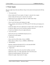
Controls the supply of power to enable/disable tuning the power on. ?Controls power-on/off the battery pack charging power supply. ? Output monitor ? Satellite A100/A105 / TECRA A7 Maintenance Manual 19 Instructs the gate array to the system block (load/logic circuit side). ? Controls... the supply of DC power supply input (AC Adapter output) to the PWM control IC of the battery pack. ? Controls forced ...
Controls the supply of power to enable/disable tuning the power on. ?Controls power-on/off the battery pack charging power supply. ? Output monitor ? Satellite A100/A105 / TECRA A7 Maintenance Manual 19 Instructs the gate array to the system block (load/logic circuit side). ? Controls... the supply of DC power supply input (AC Adapter output) to the PWM control IC of the battery pack. ? Controls forced ...
Maintenance Manual
Page 38
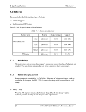
... off-state charge when the system is powered off state and detects a full charge. ? When the AC adapter and battery pack are attached to the computer, the LPC 47N249 controls the charge on . 20 Satellite A100/A105 / TECRA A7 Maintenance Manual Main battery pack ? Real time clock (RTC) battery Table 1-5 lists the specifications of these...
... off-state charge when the system is powered off state and detects a full charge. ? When the AC adapter and battery pack are attached to the computer, the LPC 47N249 controls the charge on . 20 Satellite A100/A105 / TECRA A7 Maintenance Manual Main battery pack ? Real time clock (RTC) battery Table 1-5 lists the specifications of these...
Maintenance Manual
Page 39
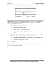
...voltage is removed. 3. The charging time exceeds the fixed limit. 1.1.3 RTC Battery The RTC battery provides power to keep the current date, time and other system information in the battery charging circuit drops below the predetermined value. 2. Any of the following conditions ... either of full charge A full charge is detected only when the battery is turned off. Satellite A100/A105 / Satellite Pro A100 / EQUIUM A100 Maintenance Manual 21 The AC adapter or battery pack is abnormal. ? 1.8 Batteries 1 Hardware Overview Table 1-6 Quick/normal charging time State Charge time ...
...voltage is removed. 3. The charging time exceeds the fixed limit. 1.1.3 RTC Battery The RTC battery provides power to keep the current date, time and other system information in the battery charging circuit drops below the predetermined value. 2. Any of the following conditions ... either of full charge A full charge is detected only when the battery is turned off. Satellite A100/A105 / Satellite Pro A100 / EQUIUM A100 Maintenance Manual 21 The AC adapter or battery pack is abnormal. ? 1.8 Batteries 1 Hardware Overview Table 1-6 Quick/normal charging time State Charge time ...

Maintenance Manual
Page 46
Yes BATTERY LED on . Yes Turn the power on ?? No Message "In Touch with Tomorrow Toshiba" displayed Yes Follow the system board diagnostic procedure in Section 2.4 No Follow the display diagnostic procedure in Section 2.3 Any error message ...the power supply diagnostic procedure in Section 2.7 Yes "Password=" displayed ?? Yes 1 Figure 2-1 Follow the HDD diagnostic procedure in Section 2.5 No Basic flowchart(1/2) Satellite A100/A105 / TECRA A7 Maintenance Manual 2-3 2.2 Basic Flowchart 2 Troubleshooting Star t Connect the AC Adapter DC IN LED on ?? OS started ??
Yes BATTERY LED on . Yes Turn the power on ?? No Message "In Touch with Tomorrow Toshiba" displayed Yes Follow the system board diagnostic procedure in Section 2.4 No Follow the display diagnostic procedure in Section 2.3 Any error message ...the power supply diagnostic procedure in Section 2.7 Yes "Password=" displayed ?? Yes 1 Figure 2-1 Follow the HDD diagnostic procedure in Section 2.5 No Basic flowchart(1/2) Satellite A100/A105 / TECRA A7 Maintenance Manual 2-3 2.2 Basic Flowchart 2 Troubleshooting Star t Connect the AC Adapter DC IN LED on ?? OS started ??
Maintenance Manual
Page 49
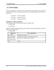
... in Green/Blue Blinking in the tables below as in Amber (at equal intervals) Off Power supply status Battery being charged Battery fully charged, with AC adapter connected Battery low *1 while driving the computer Else 2-6 Satellite A100/A105 / TECRA A7 Maintenance Manual Procedure 1 Procedure 2 Procedure 3 Power Icon Check Connection Check Replacement Check Procedure 1 Power Icon...
... in Green/Blue Blinking in the tables below as in Amber (at equal intervals) Off Power supply status Battery being charged Battery fully charged, with AC adapter connected Battery low *1 while driving the computer Else 2-6 Satellite A100/A105 / TECRA A7 Maintenance Manual Procedure 1 Procedure 2 Procedure 3 Power Icon Check Connection Check Replacement Check Procedure 1 Power Icon...
Maintenance Manual
Page 50
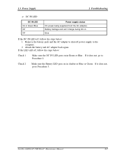
... the computer. 2. DC IN LED DC IN LED On in Green/Blue Off Off Power supply status DC power being supplied (from the AC adapter) Battery damage and can't charge during DC-in Green or Blue . If the LED still off , follow the steps below : 1. If it does not, go ... below : Check 1 Make sure the DC IN LED goes on in Amber or Blue or Green . Remove the battery pack and the AC adapter to shut off power supply to Procedure 3. Check 2 Make sure the Battery LED goes on in . Satellite A100/A105 / TECRA A7 Maintenance Manual 2-7 Attach the battery and AC adapter back again.
... the computer. 2. DC IN LED DC IN LED On in Green/Blue Off Off Power supply status DC power being supplied (from the AC adapter) Battery damage and can't charge during DC-in Green or Blue . If the LED still off , follow the steps below : 1. If it does not, go ... below : Check 1 Make sure the DC IN LED goes on in Amber or Blue or Green . Remove the battery pack and the AC adapter to shut off power supply to Procedure 3. Check 2 Make sure the Battery LED goes on in . Satellite A100/A105 / TECRA A7 Maintenance Manual 2-7 Attach the battery and AC adapter back again.

Maintenance Manual
Page 51
... corre ctly, perform Check 2. Procedure 3 Replacement Check The system board, power supply board, or CPU may be faulty. If the battery pack is still not working properly, perform Check 2. 2 Troubleshooting 2.3 Power Supply Procedure 2 Connection Check Power is supplied to the system... board as illustrated below: AC adaptor System board AC power cord AC adaptor cord Battery pack Follow the steps below : Check 1 Replace the power supply board with a new one . 2-8 Satellite A100/A105 / TECRA A7 Maintenance Manual Check 2 Connect a new AC adaptor and AC power cord...
... corre ctly, perform Check 2. Procedure 3 Replacement Check The system board, power supply board, or CPU may be faulty. If the battery pack is still not working properly, perform Check 2. 2 Troubleshooting 2.3 Power Supply Procedure 2 Connection Check Power is supplied to the system... board as illustrated below: AC adaptor System board AC power cord AC adaptor cord Battery pack Follow the steps below : Check 1 Replace the power supply board with a new one . 2-8 Satellite A100/A105 / TECRA A7 Maintenance Manual Check 2 Connect a new AC adaptor and AC power cord...
Maintenance Manual
Page 52
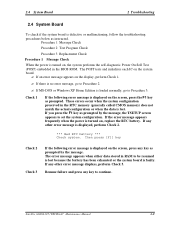
... in the BIOS ROM. If any other error message is displayed, perform Check 2. *** Bad RTC battery *** Check system. Then press [F1] key Check 2 Check 3 If the following error message is displayed on the display, perform Check 1. ? Satellite A100/A105 / TECRA A7 Maintenance Manual 2-9 Check 1 If the following error message is displayed on , the...
... in the BIOS ROM. If any other error message is displayed, perform Check 2. *** Bad RTC battery *** Check system. Then press [F1] key Check 2 Check 3 If the following error message is displayed on the display, perform Check 1. ? Satellite A100/A105 / TECRA A7 Maintenance Manual 2-9 Check 1 If the following error message is displayed on , the...
Maintenance Manual
Page 98
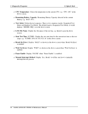
... the above screen; ? Manual Interrupt Method: Display 'Esc: Break' to tell the user how to manually interrupt the test process. 22 Satellite A100/A105 / TECRA A7 Maintenance Manual 3 Diagnostic Programs 3.2 Quick Start ? Start Test Time (S.TIME): Display the test start time for the current ...test item or the test script, e.g. 'S.TIME: 2004-01-04 19:21:16' in the above screen; ? Remaining Battery Capacity: Remaining Battery Capacity detected...
... the above screen; ? Manual Interrupt Method: Display 'Esc: Break' to tell the user how to manually interrupt the test process. 22 Satellite A100/A105 / TECRA A7 Maintenance Manual 3 Diagnostic Programs 3.2 Quick Start ? Start Test Time (S.TIME): Display the test start time for the current ...test item or the test script, e.g. 'S.TIME: 2004-01-04 19:21:16' in the above screen; ? Remaining Battery Capacity: Remaining Battery Capacity detected...

Maintenance Manual
Page 101
... confirmation while an error occurs. ? Test Order Specify the order of the following options: ? choose 'Random' to assist the test processes, such as Mouse test; Satellite A100/A105 / TECRA A7 Maintenance Manual 25 Monitor Battery Life Monitor the remaining battery capacity (percent). 3.3 Option 3 Diagnostic Programs ?
... confirmation while an error occurs. ? Test Order Specify the order of the following options: ? choose 'Random' to assist the test processes, such as Mouse test; Satellite A100/A105 / TECRA A7 Maintenance Manual 25 Monitor Battery Life Monitor the remaining battery capacity (percent). 3.3 Option 3 Diagnostic Programs ?

Maintenance Manual
Page 137
There are three kind s of LEDs test including: (1). Power LED , Battery LED , etc. (3). Subtest 02 Mouse Test Check whether the point devices work normally. Satellite A100/A105 / TECRA A7 Maintenance Manual 61 Keyboard Data Line Test Check whether the keyboard data line works normally. 2. Caps Lock LED, Num Lock LED and Scroll ...
There are three kind s of LEDs test including: (1). Power LED , Battery LED , etc. (3). Subtest 02 Mouse Test Check whether the point devices work normally. Satellite A100/A105 / TECRA A7 Maintenance Manual 61 Keyboard Data Line Test Check whether the keyboard data line works normally. 2. Caps Lock LED, Num Lock LED and Scroll ...

Maintenance Manual
Page 148
... Assembly Procedures 4-5 Tools and Equipment 4-6 Screw Tightening Torque 4-6 Colors of Screw Shanks 4-7 Symbols of Screws on the Computer Body 4-7 Symbol examples 4-7 Removing the Battery Pack 4-8 Installing the Battery Pack 4-9 Removing the PCI Expresss Card 4-10 Installing the PCI Expresss Card 4-11 Removing the Optional PC Card 4-12 Installing the Optional PC Card...MDC Card 4-21 4.2 HDD ...4-22 Removing the HDD 4-22 Installing the HDD 4-24 4.3 Speaker Cover and Keyboard 4-24 Removing the Speaker Cover and Keyboard 4-25 Satellite A100/A105 / TECRA A7 Maintenance Manual 4-iii
... Assembly Procedures 4-5 Tools and Equipment 4-6 Screw Tightening Torque 4-6 Colors of Screw Shanks 4-7 Symbols of Screws on the Computer Body 4-7 Symbol examples 4-7 Removing the Battery Pack 4-8 Installing the Battery Pack 4-9 Removing the PCI Expresss Card 4-10 Installing the PCI Expresss Card 4-11 Removing the Optional PC Card 4-12 Installing the Optional PC Card...MDC Card 4-21 4.2 HDD ...4-22 Removing the HDD 4-22 Installing the HDD 4-24 4.3 Speaker Cover and Keyboard 4-24 Removing the Speaker Cover and Keyboard 4-25 Satellite A100/A105 / TECRA A7 Maintenance Manual 4-iii


