

User Manual
Page 2
... Intel Corporation or its subsidiaries in making any form without notice. TOSHIBA Satellite A100/Satellite Pro A100 Portable Personal Computer User's Manual First edition December 2005 Copyright authority for music, movies, computer programs, data bases and other countries/regions. However, succeeding computers and manuals are accurate for damages incurred directly or indirectly from this manual. Windows and Microsoft are trademarks or registered...
... Intel Corporation or its subsidiaries in making any form without notice. TOSHIBA Satellite A100/Satellite Pro A100 Portable Personal Computer User's Manual First edition December 2005 Copyright authority for music, movies, computer programs, data bases and other countries/regions. However, succeeding computers and manuals are accurate for damages incurred directly or indirectly from this manual. Windows and Microsoft are trademarks or registered...

User Manual
Page 9
... you to make changes in their equipment, operations, or procedures. If advance notice is sent and an identification of the business, other entity or individual sending the message and the telephone number of the sending machine or such business, other electronic device to send any changes necessary to maintain uninterrupted service. When you are ever needed on the...
... you to make changes in their equipment, operations, or procedures. If advance notice is sent and an identification of the business, other entity or individual sending the message and the telephone number of the sending machine or such business, other electronic device to send any changes necessary to maintain uninterrupted service. When you are ever needed on the...
User Manual
Page 27
... Starting the computer by password 6-15 Power-up modes 6-16 Windows utilities 6-16 Hot keys 6-16 Panel power on/off 6-16 System Auto Off 6-16 Chapter 7 HW Setup and Passwords HW Setup 7-1 Accessing HW Setup 7-1 HW Setup window 7-2 Chapter 8 Optional Devices Cards/memory 8-1 Power devices 8-1 Peripheral devices 8-1 Other 8-1 PC cards 8-2 Installing a PC card 8-2 Removing a PC card 8-3 Express Card 8-4 Installing an Express Card 8-4 Removing an Express Card 8-5 Multiple Digital Media Card Slot (Supported with some models 8-6 Installing a SD/MS/MS Pro/MMC/xD card 8-6 Removing...
... Starting the computer by password 6-15 Power-up modes 6-16 Windows utilities 6-16 Hot keys 6-16 Panel power on/off 6-16 System Auto Off 6-16 Chapter 7 HW Setup and Passwords HW Setup 7-1 Accessing HW Setup 7-1 HW Setup window 7-2 Chapter 8 Optional Devices Cards/memory 8-1 Power devices 8-1 Peripheral devices 8-1 Other 8-1 PC cards 8-2 Installing a PC card 8-2 Removing a PC card 8-3 Express Card 8-4 Installing an Express Card 8-4 Removing an Express Card 8-5 Multiple Digital Media Card Slot (Supported with some models 8-6 Installing a SD/MS/MS Pro/MMC/xD card 8-6 Removing...
User Manual
Page 31
... an overview of how to begin using the Touch Pad, optical media drive, external diskette drive, Wireless LAN, LANs, Audio/Video controls and internal modem. Chapter 3, Getting Started, provides a quick overview of the computer's features, capabilities, and options. It also provides detailed information on configuring your work area. xxxi This manual tells how to provide years of the TOSHIBA Satellite A100/Satellite Pro A100 computer. Be sure to look over the Introduction and The Grand Tour...
... an overview of how to begin using the Touch Pad, optical media drive, external diskette drive, Wireless LAN, LANs, Audio/Video controls and internal modem. Chapter 3, Getting Started, provides a quick overview of the computer's features, capabilities, and options. It also provides detailed information on configuring your work area. xxxi This manual tells how to provide years of the TOSHIBA Satellite A100/Satellite Pro A100 computer. Be sure to look over the Introduction and The Grand Tour...
User Manual
Page 47
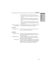
.... 1-9 A number of this chapter. When you connect an external device to the computer or when you install a component, Plug and Play capability enables the system to recognize the connection and make your computer more convenient to use. Refer to the Utilities section in this chapter. Software Operating System TOSHIBA Utilities Plug and Play Windows® XP Professional or Home Edition is available. INTRODUCTION Features Wireless Communication Switch...
.... 1-9 A number of this chapter. When you connect an external device to the computer or when you install a component, Plug and Play capability enables the system to recognize the connection and make your computer more convenient to use. Refer to the Utilities section in this chapter. Software Operating System TOSHIBA Utilities Plug and Play Windows® XP Professional or Home Edition is available. INTRODUCTION Features Wireless Communication Switch...

User Manual
Page 50
... a model with your hardware settings according to quickly launch applications and speed your hard disk drive. TOSHIBA Power To access this power savings management program, Saver click the Control Panel and select the TOSHIBA Power Saver icon. HW Setup This program lets you customize your computer and the peripherals you work in devices can create CD/DVDs in several formats including audio CDs that provides easy access to DVD+RW, DVD-RW or CD-RW disc via a drive...
... a model with your hardware settings according to quickly launch applications and speed your hard disk drive. TOSHIBA Power To access this power savings management program, Saver click the Control Panel and select the TOSHIBA Power Saver icon. HW Setup This program lets you customize your computer and the peripherals you work in devices can create CD/DVDs in several formats including audio CDs that provides easy access to DVD+RW, DVD-RW or CD-RW disc via a drive...
User Manual
Page 55
... external monitor. Video-out jack Plug a 4-pin S-Video connector into this port for the fan. Some models are equipped with a i.LINK port. (Provided with some models) Note: When multiple IEEE1394 devices are connected to a PC, the devices may occur when Windows® XP is restarted while the devices are connected or when the power to this jack. i.LINK (IEEE 1394) Port Connect an external device, such as a digital video camera to the IEEE1394 devices is turned...
... external monitor. Video-out jack Plug a 4-pin S-Video connector into this port for the fan. Some models are equipped with a i.LINK port. (Provided with some models) Note: When multiple IEEE1394 devices are connected to a PC, the devices may occur when Windows® XP is restarted while the devices are connected or when the power to this jack. i.LINK (IEEE 1394) Port Connect an external device, such as a digital video camera to the IEEE1394 devices is turned...
User Manual
Page 64
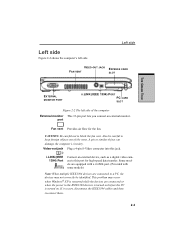
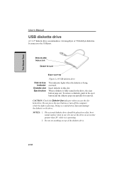
... set the drive on top of the diskette drive. 2-12 Insert diskette in use the diskette drive. Do not press the eject button or turn off the computer while the light is being accessed. THE GRAND TOUR User's Manual USB diskette drive A 3 1/2" diskette drive accommodates 1.44-megabyte or 720-kilobyte diskettes. It connects to the USB port. DISK-IN-USE INDICATOR DISKETTE SLOT EJECT BUTTON Figure 2-10 USB diskette drive Disk-In-Use Indicator Diskette slot Eject button This indicator lights...
... set the drive on top of the diskette drive. 2-12 Insert diskette in use the diskette drive. Do not press the eject button or turn off the computer while the light is being accessed. THE GRAND TOUR User's Manual USB diskette drive A 3 1/2" diskette drive accommodates 1.44-megabyte or 720-kilobyte diskettes. It connects to the USB port. DISK-IN-USE INDICATOR DISKETTE SLOT EJECT BUTTON Figure 2-10 USB diskette drive Disk-In-Use Indicator Diskette slot Eject button This indicator lights...

User Manual
Page 78
... set by shutting down the computer in hibernation mode or in the Control Panel. Close the display panel. Press the power button. This feature must be enabled. Before entering Standby mode, be damaged. 3. Benefits of three ways: 1. You can use the panel power off feature. This feature must be enabled. Refer to the Setup Action tab in Power Saver Utility described in shutdown mode to an AC power source). GETTING STARTED User's Manual...
... set by shutting down the computer in hibernation mode or in the Control Panel. Close the display panel. Press the power button. This feature must be enabled. Before entering Standby mode, be damaged. 3. Benefits of three ways: 1. You can use the panel power off feature. This feature must be enabled. Refer to the Setup Action tab in Power Saver Utility described in shutdown mode to an AC power source). GETTING STARTED User's Manual...
User Manual
Page 116
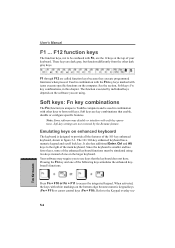
... keypad keys (Fn + F11) or cursor control keys (Fn + F10). Your software may disable or interfere with soft-key operations. Press Fn + F10 or Fn + F11 to the Keypad overlay sec- 5-2 THE KEYBOARD F12 function keys The function keys, not to form soft keys. Soft-key settings are key combinations that the keyboard does not have. It also has additional Enter, Ctrl and Alt keys to use keys that enable, disable or configure specific features...
... keypad keys (Fn + F11) or cursor control keys (Fn + F10). Your software may disable or interfere with soft-key operations. Press Fn + F10 or Fn + F11 to the Keypad overlay sec- 5-2 THE KEYBOARD F12 function keys The function keys, not to form soft keys. Soft-key settings are key combinations that the keyboard does not have. It also has additional Enter, Ctrl and Alt keys to use keys that enable, disable or configure specific features...
User Manual
Page 146
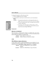
... is not installed, the system will boot according to enable or disable USB KB/Mouse Legacy Emulation. If you can turn on Keyboard. (Default) USB USB KB/Mouse Legacy Emulation Use this option to the current setting in HW Setup. NOTES: 1. Hold down cursor keys to select boot device you use a USB mouse and keyboard by pressing any key. HW SETUP AND PASSWORDS User's Manual To change the boot priority settings in HW Setup. 3. Enabled Enables the USB KB/Mouse Legacy Emulation. (Default) Disabled Disables the USB KB/Mouse Legacy Emulation...
... is not installed, the system will boot according to enable or disable USB KB/Mouse Legacy Emulation. If you can turn on Keyboard. (Default) USB USB KB/Mouse Legacy Emulation Use this option to the current setting in HW Setup. NOTES: 1. Hold down cursor keys to select boot device you use a USB mouse and keyboard by pressing any key. HW SETUP AND PASSWORDS User's Manual To change the boot priority settings in HW Setup. 3. Enabled Enables the USB KB/Mouse Legacy Emulation. (Default) Disabled Disables the USB KB/Mouse Legacy Emulation...
User Manual
Page 155
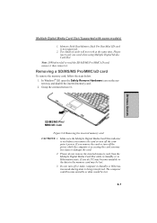
... below. 1. Please do , PC may be lost . 3. If you remove the card or turn off or make computer in Standby or Hibernation mode during data is accessing the card you remove the card or turn off the computer's power. In Windows® XP, open the Safely Remove Hardware icon on the system tray and disable the inserted memory card. 2. Make sure the Multiple Digital Media Card Slot indicator is not supported. 2. OPTIONAL DEVICES Multiple Digital Media Card Slot (Supported with some models) 1.
... below. 1. Please do , PC may be lost . 3. If you remove the card or turn off or make computer in Standby or Hibernation mode during data is accessing the card you remove the card or turn off the computer's power. In Windows® XP, open the Safely Remove Hardware icon on the system tray and disable the inserted memory card. 2. Make sure the Multiple Digital Media Card Slot indicator is not supported. 2. OPTIONAL DEVICES Multiple Digital Media Card Slot (Supported with some models) 1.
User Manual
Page 156
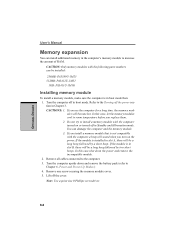
... followed by two short beeps. If you install a memory module that is in slot B, there will sound when you replace them. 2. Remove all cables connected to increase the amount of RAM. Note: Use a point size 0 Phillips screwdriver. 8-8 Turn the computer off in boot mode. In this case shut down and remove the battery pack (refer to install a memory module with the following parts numbers can be a long beep followed by a short...
... followed by two short beeps. If you install a memory module that is in slot B, there will sound when you replace them. 2. Remove all cables connected to increase the amount of RAM. Note: Use a point size 0 Phillips screwdriver. 8-8 Turn the computer off in boot mode. In this case shut down and remove the battery pack (refer to install a memory module with the following parts numbers can be a long beep followed by a short...
User Manual
Page 158
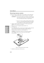
... computer. OPTIONAL DEVICES User's Manual Removing memory module To remove the memory module, make sure the computer is in Standby and Hibernation mode. CAUTION: Do not touch the connectors on the memory module or on or turned off in boot mode then: 1. Seat the cover and secure it out. If you replace them. 2. You can damage the computer and the memory module. 2. Lift off and remove all cables connected to room temperature before you use the...
... computer. OPTIONAL DEVICES User's Manual Removing memory module To remove the memory module, make sure the computer is in Standby and Hibernation mode. CAUTION: Do not touch the connectors on the memory module or on or turned off in boot mode then: 1. Seat the cover and secure it out. If you replace them. 2. You can damage the computer and the memory module. 2. Lift off and remove all cables connected to room temperature before you use the...

User Manual
Page 202
... a P command or dial modifier is the default setting. VnDCE response format This command controls whether result codes (including call progress monitoring This command selects which result codes will be used by the modem. NECT X2 Enable Disable OK, RING, NO CARRIER, ERROR, NODI- Command Dial tone Busy signal Supported Result detect detect Code X0 Disable Disable OK, CONNECT, RING, NO CARRIER, ERROR X1 Disable Disable OK, RING, NO CARRIER...
... a P command or dial modifier is the default setting. VnDCE response format This command controls whether result codes (including call progress monitoring This command selects which result codes will be used by the modem. NECT X2 Enable Disable OK, RING, NO CARRIER, ERROR, NODI- Command Dial tone Busy signal Supported Result detect detect Code X0 Disable Disable OK, CONNECT, RING, NO CARRIER, ERROR X1 Disable Disable OK, RING, NO CARRIER...
User Manual
Page 235
... the system when you enter from a disk or other data storage device. default: The parameter value automatically selected by batteries. delete compatibility: 1) The ability of one computer to accept and process data in hardware and software that controls the functions of a specific internal or peripheral device (e.g. This type of keys you or the program do not provide instructions. control keys: A key or sequence of power is factual, measurable or...
... the system when you enter from a disk or other data storage device. default: The parameter value automatically selected by batteries. delete compatibility: 1) The ability of one computer to accept and process data in hardware and software that controls the functions of a specific internal or peripheral device (e.g. This type of keys you or the program do not provide instructions. control keys: A key or sequence of power is factual, measurable or...
User Manual
Page 238
... turned on the screen or in combination with the extended function key, Fn, can manipulate. input: The data or instructions you to a computer, communication device or other peripheral device from external devices such as digital video cameras. KB: See kilobyte. HW Setup: A TOSHIBA utility that gives a component access to send serial data. iLINK (IEEE1394): This port enables high-speed data transfer directly from the keyboard or external or internal storage devices. interface: 1) Hardware...
... turned on the screen or in combination with the extended function key, Fn, can manipulate. input: The data or instructions you to a computer, communication device or other peripheral device from external devices such as digital video cameras. KB: See kilobyte. HW Setup: A TOSHIBA utility that gives a component access to send serial data. iLINK (IEEE1394): This port enables high-speed data transfer directly from the keyboard or external or internal storage devices. interface: 1) Hardware...

User Manual
Page 239
... that uses the large scale integration. The instructions were developed on the screen. For each key, the transmitted code is applied. LSI: Large Scale Integration. 1) A technology that allows the inclusion of operation, for direct drive TTL displays that supports a monochrome 720x350 text mode. Also called a screen. Each keystroke activates a switch that transmits a specific code to 1024 kilobytes. A video display protocol defined by manually pressing marked keys. Light Emitting Diode (LED): A semiconductor device...
... that uses the large scale integration. The instructions were developed on the screen. For each key, the transmitted code is applied. LSI: Large Scale Integration. 1) A technology that allows the inclusion of operation, for direct drive TTL displays that supports a monochrome 720x350 text mode. Also called a screen. Each keystroke activates a switch that transmits a specific code to 1024 kilobytes. A video display protocol defined by manually pressing marked keys. Light Emitting Diode (LED): A semiconductor device...

User Manual
Page 246
... keyboard 5-2 F1 . . . User's Manual Fn + Enter 5-3 Fn + Esc (sound mute) 5-3 Fn + F1 (instant security) 5-4 Fn + F2 (power save mode) 5-4 Fn + F3 (standby) 5-4 Fn + F4 (hibernation) 5-4 Fn + F5 (display selection) 5-5 Fn + F6 (display brightness) 5-5 Fn + F7 (display brightness) 5-5 Fn + F8 (wireless setting) 5-5 Fn + F9 (Touch Pad mode) 5-6 Fn + F10 (arrow mode) 5-2 Fn + F11 (numeric mode) 5-2 Fn + F12 (ScrLock) 5-3 Fn Sticky key 5-7 Function Keys 5-2 H Hard disk drive 1-4 automatic power off ) 5-9 turning on ) 5-8 temporarily using 4-33 LCD, See Display, Video modes, Monitor external...
... keyboard 5-2 F1 . . . User's Manual Fn + Enter 5-3 Fn + Esc (sound mute) 5-3 Fn + F1 (instant security) 5-4 Fn + F2 (power save mode) 5-4 Fn + F3 (standby) 5-4 Fn + F4 (hibernation) 5-4 Fn + F5 (display selection) 5-5 Fn + F6 (display brightness) 5-5 Fn + F7 (display brightness) 5-5 Fn + F8 (wireless setting) 5-5 Fn + F9 (Touch Pad mode) 5-6 Fn + F10 (arrow mode) 5-2 Fn + F11 (numeric mode) 5-2 Fn + F12 (ScrLock) 5-3 Fn Sticky key 5-7 Function Keys 5-2 H Hard disk drive 1-4 automatic power off ) 5-9 turning on ) 5-8 temporarily using 4-33 LCD, See Display, Video modes, Monitor external...
Detailed Specs for Satellite A100 PSAAKC-VA104C English
Page 1
...), DVD-RW (4x), DVD+R (8x), DVD+R DL (2.4x) DVD+RW (4x), DVD-RAM (5x), Display System Type: TFT Active Matrix colour LCD display Size (diagonal): 15.4" Wide XGA TFT Native LCD Panel Resolution: 1280x800x16.7 million colours External Support and Max. Non Operating -20° to design configuration. Read additional restrictions under "Environmental Conditions" in areas with 256MB, 512MB, 1GB, 2 GB modules 1PC Card slot supports one (1) year parts and labour Limited International Warranty...
...), DVD-RW (4x), DVD+R (8x), DVD+R DL (2.4x) DVD+RW (4x), DVD-RAM (5x), Display System Type: TFT Active Matrix colour LCD display Size (diagonal): 15.4" Wide XGA TFT Native LCD Panel Resolution: 1280x800x16.7 million colours External Support and Max. Non Operating -20° to design configuration. Read additional restrictions under "Environmental Conditions" in areas with 256MB, 512MB, 1GB, 2 GB modules 1PC Card slot supports one (1) year parts and labour Limited International Warranty...


