
User Manual
Page 14
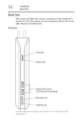
For a description of the dynadock™ Front view Power light Indicator light Powered USB 2.0 ports (USB Sleep and Charge) Microphone jack Headphone jack (Sample Illustration) Lights and connectors on the front of each component, please refer to the table beneath each illustration. 14 Introduction Quick Tour Quick Tour This section identifies the various components of the dynadock™ wireless U.
For a description of the dynadock™ Front view Power light Indicator light Powered USB 2.0 ports (USB Sleep and Charge) Microphone jack Headphone jack (Sample Illustration) Lights and connectors on the front of each component, please refer to the table beneath each illustration. 14 Introduction Quick Tour Quick Tour This section identifies the various components of the dynadock™ wireless U.

User Manual
Page 15
... phones) even when the dynadock™ is disconnected from your computer or your USB device came with the AC adaptor. Note 3: If your computer is off . Off: Computer is docked. Note 1: Some USB devices may not be sure to connect the device to headphones/headsets/speakers. A standard ... audio input from the AC adaptor. Component Power light Indicator light Powered USB 2.0 ports (USB Sleep and Charge ports) Microphone jack Headphone jack Introduction 15 Quick Tour Description Glows blue when power is in process. Indicates the status of the USB ports, you may not...
... phones) even when the dynadock™ is disconnected from your computer or your USB device came with the AC adaptor. Note 3: If your computer is off . Off: Computer is docked. Note 1: Some USB devices may not be sure to connect the device to headphones/headsets/speakers. A standard ... audio input from the AC adaptor. Component Power light Indicator light Powered USB 2.0 ports (USB Sleep and Charge ports) Microphone jack Headphone jack Introduction 15 Quick Tour Description Glows blue when power is in process. Indicates the status of the USB ports, you may not...

User Manual
Page 16
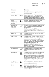
16 Introduction Quick Tour Back view Antennas Antenna switch Line out (Headphones, Speakers) S/PDIF port Network port USB 2.0 ports DVI-I video port Mini USB jack Security Lock Slot DC-IN (Sample Illustration) Connections on the back of the dynadock™
16 Introduction Quick Tour Back view Antennas Antenna switch Line out (Headphones, Speakers) S/PDIF port Network port USB 2.0 ports DVI-I video port Mini USB jack Security Lock Slot DC-IN (Sample Illustration) Connections on the back of the dynadock™
User Manual
Page 17
...the provided USB cable, used to deter theft. Connection point for AC adaptor (provided). Socket for digital audio equipment (e.g. Note: The dynadock™ requires an external power supply, as optical disk drives and hard disk drives, have high power requirements. A standard 3.5 mm ... USB jack Security lock slot DC-IN Introduction 17 Quick Tour Description Send and receive wireless signals to/from the computer's USB bus. Connection point for stereo audio output to headphones/headsets/speakers. Connection point for USB 2.0 and 1.1 devices. Connection points for a ...
...the provided USB cable, used to deter theft. Connection point for AC adaptor (provided). Socket for digital audio equipment (e.g. Note: The dynadock™ requires an external power supply, as optical disk drives and hard disk drives, have high power requirements. A standard 3.5 mm ... USB jack Security lock slot DC-IN Introduction 17 Quick Tour Description Send and receive wireless signals to/from the computer's USB bus. Connection point for stereo audio output to headphones/headsets/speakers. Connection point for USB 2.0 and 1.1 devices. Connection points for a ...
User Manual
Page 30
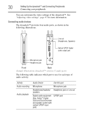
...) See "Adjusting video settings" page 47 for each type of the dynadock™. Line out (Headphones, Speakers) Optical S/PDIF digital audio output jack Microphone jack Headphone jack Front Back (Sample Illustration) dynadock™ wireless U audio ports The following illustrations. 30 Setting Up the dynadock™ and Connecting Peripherals Connecting your peripherals You can customize the video...
...) See "Adjusting video settings" page 47 for each type of the dynadock™. Line out (Headphones, Speakers) Optical S/PDIF digital audio output jack Microphone jack Headphone jack Front Back (Sample Illustration) dynadock™ wireless U audio ports The following illustrations. 30 Setting Up the dynadock™ and Connecting Peripherals Connecting your peripherals You can customize the video...

User Manual
Page 51
...icon in the System tray/Notification Area of your Windows® desktop. (Sample Image) TOSHIBA dynadock Utility icon NOTE If the icon is not visible in your System tray/Notification Area, make sure the dynadock™ is connected and docked, and then click the Show Hidden Icons button [ ...the Recording tab of the dialog box, select one of the following : ❖ To use the dynadock's Headphone/Speakers/Line out jack, select USB Multi-Channel Audio Device. ❖ To use the dynadock's Microphone jack, select USB Multi-Channel Audio Device. from the menu. 3 On the Playback tab of...
...icon in the System tray/Notification Area of your Windows® desktop. (Sample Image) TOSHIBA dynadock Utility icon NOTE If the icon is not visible in your System tray/Notification Area, make sure the dynadock™ is connected and docked, and then click the Show Hidden Icons button [ ...the Recording tab of the dialog box, select one of the following : ❖ To use the dynadock's Headphone/Speakers/Line out jack, select USB Multi-Channel Audio Device. ❖ To use the dynadock's Microphone jack, select USB Multi-Channel Audio Device. from the menu. 3 On the Playback tab of...

User Manual
Page 52
...; is connected and docked, and then click the Show Hidden Icons button [ ], if necessary, to the dynadock™. To enable virtual 7.1-channel sound: 1 Connect your two-channel speakers or headphones to the dynadock™. 2 Click the USB Multi-Channel Audio Device icon in the System tray/Notification Area of your Windows® desktop... quality With the included software, you enabled in your microphone to the jack you can experience 7.1-channel virtual surround sound through two-channel speakers or headphones connected to display hidden icons.
...; is connected and docked, and then click the Show Hidden Icons button [ ], if necessary, to the dynadock™. To enable virtual 7.1-channel sound: 1 Connect your two-channel speakers or headphones to the dynadock™. 2 Click the USB Multi-Channel Audio Device icon in the System tray/Notification Area of your Windows® desktop... quality With the included software, you enabled in your microphone to the jack you can experience 7.1-channel virtual surround sound through two-channel speakers or headphones connected to display hidden icons.

User Manual
Page 53
Using the dynadock™ and Adjusting Settings 53 Adjusting audio settings (Sample Image) The USB Multi-Channel Audio Device Utility 3 In the Analog Output section of the dialog box, select one of the following: ❖ Headphone or [ ], if you connected headphones in step 1. ❖ 2 Speakers, if you connected speakers in step 1. 4 In the DSP Mode section of the dialog box, click the 7.1 Virtual Speaker Shifter button. (Sample Image) The 7.1 Virtual Speaker Shifter button 5 Click the Advanced Settings button next to DSP Mode. (Sample Image) The Advanced Settings button
Using the dynadock™ and Adjusting Settings 53 Adjusting audio settings (Sample Image) The USB Multi-Channel Audio Device Utility 3 In the Analog Output section of the dialog box, select one of the following: ❖ Headphone or [ ], if you connected headphones in step 1. ❖ 2 Speakers, if you connected speakers in step 1. 4 In the DSP Mode section of the dialog box, click the 7.1 Virtual Speaker Shifter button. (Sample Image) The 7.1 Virtual Speaker Shifter button 5 Click the Advanced Settings button next to DSP Mode. (Sample Image) The Advanced Settings button

User Manual
Page 55
...Reset Manually change the location of sound quality. You can now listen to virtual 7.1-channel sound through your audio equipment. Using the dynadock™ and Adjusting Settings 55 Adjusting audio settings Control(s) Click to the desired location. Enabling digital S/PDIF output Using the S/...This control enables you can be enhanced by dragging it closer to your twochannel headphones or speakers. You will also need a TOSlink optical digital audio cable (purchased separately), to connect the dynadock™ to the listener. You will need to enable the S/PDIF output...
...Reset Manually change the location of sound quality. You can now listen to virtual 7.1-channel sound through your audio equipment. Using the dynadock™ and Adjusting Settings 55 Adjusting audio settings Control(s) Click to the desired location. Enabling digital S/PDIF output Using the S/...This control enables you can be enhanced by dragging it closer to your twochannel headphones or speakers. You will also need a TOSlink optical digital audio cable (purchased separately), to connect the dynadock™ to the listener. You will need to enable the S/PDIF output...

User Manual
Page 65
Make sure the cable connecting the audio device to the dynadock's Line out, Headphone, or Microphone jack is restarted. The audio port on page 50. Check that the Mute all /Mute checkboxes in Microsoft® Windows® are not ... disabled when the computer is docked. Close your media player application, if it is no sound coming from the computer's internal speakers, or from the headphones/headset connected directly to your media player application. There is running . Close the media player application, if it is no sound coming from standby/ sleep...
Make sure the cable connecting the audio device to the dynadock's Line out, Headphone, or Microphone jack is restarted. The audio port on page 50. Check that the Mute all /Mute checkboxes in Microsoft® Windows® are not ... disabled when the computer is docked. Close your media player application, if it is no sound coming from the computer's internal speakers, or from the headphones/headset connected directly to your media player application. There is running . Close the media player application, if it is no sound coming from standby/ sleep...

User Manual
Page 72
... digital audio output) 1 Ethernet port (10/100 Base-T Ethernet RJ-45 connector) 1 DVI-I port (Digital 24-pin Female Connector) 1 Microphone connector (3.5 mm mono audio in) 1 Headphones connector (3.5 mm stereo audio out) 1 Line out(3.5 mm stereo audio out) 1 DC-IN socket 1 Security lock slot Supported Video Display Windows® XP: Mirror Desktop...
... digital audio output) 1 Ethernet port (10/100 Base-T Ethernet RJ-45 connector) 1 DVI-I port (Digital 24-pin Female Connector) 1 Microphone connector (3.5 mm mono audio in) 1 Headphones connector (3.5 mm stereo audio out) 1 Line out(3.5 mm stereo audio out) 1 DC-IN socket 1 Security lock slot Supported Video Display Windows® XP: Mirror Desktop...

User Manual
Page 74
...peripherals 28 to a network 28 USB cable to computer 26 USB devices 31 connecting/disconnecting dynadock™ from computer 39 Connection Rules changing 39 connection/docking issues 66 contacting Toshiba 69 D DC-IN connection 21 DC-IN port 17 disable/enable pop-up messages 40...47 F FCC information 5 front view Quick Tour 14 G general specifications dynadock™ 72 H Headphone jack 15, 17 Hibernation mode 57 Host/Device Drivers uninstalling 41 I icon safety 2 icons safety 2 indicator light 15 inserting wireless USB adaptor 25 install software 21 instructions safety 3 introduction 12 issues ...
...peripherals 28 to a network 28 USB cable to computer 26 USB devices 31 connecting/disconnecting dynadock™ from computer 39 Connection Rules changing 39 connection/docking issues 66 contacting Toshiba 69 D DC-IN connection 21 DC-IN port 17 disable/enable pop-up messages 40...47 F FCC information 5 front view Quick Tour 14 G general specifications dynadock™ 72 H Headphone jack 15, 17 Hibernation mode 57 Host/Device Drivers uninstalling 41 I icon safety 2 icons safety 2 indicator light 15 inserting wireless USB adaptor 25 install software 21 instructions safety 3 introduction 12 issues ...

User Manual
Page 75
...O Optical S/PDIF 17 Other issues 69 P package contents 18 peripherals connecting 28 physical dimensions dynadock™ 71 pop-up messages disable/enable 40 port DC-IN 17 Headphone jack 15 Line out (Headphones, Speakers) 17 Microphone jack 15 Mini USB 17 Mini USB, connecting 26 Network 17 Optical...enabling 55 safety icons 2 instructions 3 security lock slot 17 dynadock™ 58 selecting Extended/Mirror mode 47 message options 44 set up USB cable connection 28 wireless connection 24 setting Sleep mode options 43 setting up the dynadock™ 20 Sleep mode 57 undocking 35 Sleep mode options ...
...O Optical S/PDIF 17 Other issues 69 P package contents 18 peripherals connecting 28 physical dimensions dynadock™ 71 pop-up messages disable/enable 40 port DC-IN 17 Headphone jack 15 Line out (Headphones, Speakers) 17 Microphone jack 15 Mini USB 17 Mini USB, connecting 26 Network 17 Optical...enabling 55 safety icons 2 instructions 3 security lock slot 17 dynadock™ 58 selecting Extended/Mirror mode 47 message options 44 set up USB cable connection 28 wireless connection 24 setting Sleep mode options 43 setting up the dynadock™ 20 Sleep mode 57 undocking 35 Sleep mode options ...

pa3686uspec.pdf
Page 1
...Toshiba Green Procurement Requirements Color: Champagne Metallic Opal & Black Product Dimensions: 1.7" x 3.1" x 8.7" (w/o base plate) Product Dimensions: 4.5" x 5.2" x 9.3" (with base plate) Product Weight: 3 lbs 4 oz Package Contents: Wireless U docking station, Wireless USB Adapter, base plate, USB 2.0 cable (for connecting dynadock... to computer during setup and can be used for wired connectivity), AC power adapter, AC power cord/cable, DVI-I Video Port (DVI to VGA adapter (Headphone) ...
...Toshiba Green Procurement Requirements Color: Champagne Metallic Opal & Black Product Dimensions: 1.7" x 3.1" x 8.7" (w/o base plate) Product Dimensions: 4.5" x 5.2" x 9.3" (with base plate) Product Weight: 3 lbs 4 oz Package Contents: Wireless U docking station, Wireless USB Adapter, base plate, USB 2.0 cable (for connecting dynadock... to computer during setup and can be used for wired connectivity), AC power adapter, AC power cord/cable, DVI-I Video Port (DVI to VGA adapter (Headphone) ...