Quick Start Guide
Page 1
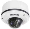
The application Adobe Reader is needed to the Toshiba website (http://www.toshiba.com). If you do not have this application, download it from the Adobe Systems Incorporated website. For information on our latest products and peripheral devices, refer to the following Website: n http://www.toshibasecurity.com If the URL changes, refer to view PDF files. Refer to the user's manual (PDF file) contained in the CD-ROM for settings, operations and other information. NETWORK CAMERA Model: IK-WR12A Quick Start Guide and Important Safeguards This guide describes the hardware installation.
The application Adobe Reader is needed to the Toshiba website (http://www.toshiba.com). If you do not have this application, download it from the Adobe Systems Incorporated website. For information on our latest products and peripheral devices, refer to the following Website: n http://www.toshibasecurity.com If the URL changes, refer to view PDF files. Refer to the user's manual (PDF file) contained in the CD-ROM for settings, operations and other information. NETWORK CAMERA Model: IK-WR12A Quick Start Guide and Important Safeguards This guide describes the hardware installation.
Quick Start Guide
Page 3
...for future reference. Windows Vista®: Microsoft® Windows Vista® Business operating system -- NOTE l The performance of the network camera may be trademarks or registered trademarks of their respective holders. Terms and Trademarks l The term "OS" is used in this quick ... l The formal name of Windows® is a trademark of Microsoft® Corporation in a convenient place for purchasing the IK-WR12A Network Camera. Before you start using the camera, read this product. -- The design, specifications, software, and quick start guide, keep it in the United States and other...
...for future reference. Windows Vista®: Microsoft® Windows Vista® Business operating system -- NOTE l The performance of the network camera may be trademarks or registered trademarks of their respective holders. Terms and Trademarks l The term "OS" is used in this quick ... l The formal name of Windows® is a trademark of Microsoft® Corporation in a convenient place for purchasing the IK-WR12A Network Camera. Before you start using the camera, read this product. -- The design, specifications, software, and quick start guide, keep it in the United States and other...
Quick Start Guide
Page 4
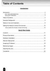
Table of Contents Introduction Introduction 2 FCC (USA)-INFORMATION 2 Terms and Trademarks 3 Table of Contents 4 Important Safeguards 5 Notes on Use and Installation 9 Setting the Network Camera Environment 10 Items needed for network camera monitoring 10 Quick Start Guide Contents 11 Physical Description 12 Hardware Installation 14 Network Deployment 17 Assigning IP Address 19 Retrieving Images 20 Adjusting the Lens 21 Completion 22 4
Table of Contents Introduction Introduction 2 FCC (USA)-INFORMATION 2 Terms and Trademarks 3 Table of Contents 4 Important Safeguards 5 Notes on Use and Installation 9 Setting the Network Camera Environment 10 Items needed for network camera monitoring 10 Quick Start Guide Contents 11 Physical Description 12 Hardware Installation 14 Network Deployment 17 Assigning IP Address 19 Retrieving Images 20 Adjusting the Lens 21 Completion 22 4
Quick Start Guide
Page 5
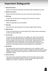
... table recommended by the manufacturer, or sold with all warnings on the product and in installation verify that there is proper ventilation so that the camera temperature operates within the recommended temperature range. 9. Any mounting of the product should follow the manufacturer's instructions, and should use a mounting accessory recommended by the...
... table recommended by the manufacturer, or sold with all warnings on the product and in installation verify that there is proper ventilation so that the camera temperature operates within the recommended temperature range. 9. Any mounting of the product should follow the manufacturer's instructions, and should use a mounting accessory recommended by the...

Quick Start Guide
Page 6
... that they exit the product. 11. Overloading Do not overload the power supply or extension cords as this video product on an unsecured location, the camera could result in a fire or electrical shock. Never intentionally spill liquid of fire or electric shock. 14. Servicing Do not attempt to be walked on...
... that they exit the product. 11. Overloading Do not overload the power supply or extension cords as this video product on an unsecured location, the camera could result in a fire or electrical shock. Never intentionally spill liquid of fire or electric shock. 14. Servicing Do not attempt to be walked on...

Quick Start Guide
Page 8
... in the literature accompanying the appliance. NO USER SERVICEABLE PARTS INSIDE. WARNING: TO REDUCE THE RISK OF FIRE OR ELECTRIC SHOCK, DO NOT SUBMERGE THIS CAMERA IN WATER. FIELD INSTALLATION MARKING: WORDED: "THIS INSTALLATION SHOULD BE MADE BY A QUALIFIED SERVICE PERSON AND SHOULD CONFORM TO ALL LOCAL CODES." 8
... in the literature accompanying the appliance. NO USER SERVICEABLE PARTS INSIDE. WARNING: TO REDUCE THE RISK OF FIRE OR ELECTRIC SHOCK, DO NOT SUBMERGE THIS CAMERA IN WATER. FIELD INSTALLATION MARKING: WORDED: "THIS INSTALLATION SHOULD BE MADE BY A QUALIFIED SERVICE PERSON AND SHOULD CONFORM TO ALL LOCAL CODES." 8
Quick Start Guide
Page 9
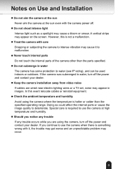
...protection to intense vibration may cause it , the trouble may get worse and an unpredictable problem may cause a bloom or smear. If the camera was submerged in water, turn off the power and contact your dealer. However, this event relocate cables or reinstall equipment. l Do not ...submerge in images. l Keep the camera installation away from video noise If cables are using the camera where the temperature is hotter or colder than the parts specified. If you are wired near electric lighting wires...
...protection to intense vibration may cause it , the trouble may get worse and an unpredictable problem may cause a bloom or smear. If the camera was submerged in water, turn off the power and contact your dealer. However, this event relocate cables or reinstall equipment. l Do not ...submerge in images. l Keep the camera installation away from video noise If cables are using the camera where the temperature is hotter or colder than the parts specified. If you are wired near electric lighting wires...
Quick Start Guide
Page 10
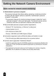
..."administrator's personal computer" in this guide. * The personal computer for network camera monitoring l Administrator's personal computer The personal computer that allows setting, operating, monitoring and other functions with the network camera is called the "user's personal computer" in the CD-ROM and install... the application by more than one personal computer at the same time. The network camera can be viewed by following the onscreen instructions.) -- Using this application from the CD-ROM supplied as Ethernet cables, and switch ...
..."administrator's personal computer" in this guide. * The personal computer for network camera monitoring l Administrator's personal computer The personal computer that allows setting, operating, monitoring and other functions with the network camera is called the "user's personal computer" in the CD-ROM and install... the application by more than one personal computer at the same time. The network camera can be viewed by following the onscreen instructions.) -- Using this application from the CD-ROM supplied as Ethernet cables, and switch ...
Quick Start Guide
Page 11
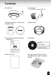
N.C. Refer to the Toshiba website (http://www.toshiba.com/tai/products/ prod_biz.jsp). l Warranty Card l CD-ROM IK-WR12A Content: User's Manual Quick Installation Guide Installation Wizard l L-type Hex Key Wrench / RJ45 Female/Female Coupler / Slica ...Alignment Sticker / Ceiling Hole Template Sticker l Bottom Base Drill hole Ceiling Hole Template Sticker l Quick Start Guide and Important Safeguards NETWORK CAMERA Model: IK-WR12A Quick Start Guide and Important Safeguards This guide describes the hardware installation. N.C. The application Adobe Reader is needed to view PDF &#...
N.C. Refer to the Toshiba website (http://www.toshiba.com/tai/products/ prod_biz.jsp). l Warranty Card l CD-ROM IK-WR12A Content: User's Manual Quick Installation Guide Installation Wizard l L-type Hex Key Wrench / RJ45 Female/Female Coupler / Slica ...Alignment Sticker / Ceiling Hole Template Sticker l Bottom Base Drill hole Ceiling Hole Template Sticker l Quick Start Guide and Important Safeguards NETWORK CAMERA Model: IK-WR12A Quick Start Guide and Important Safeguards This guide describes the hardware installation. N.C. The application Adobe Reader is needed to view PDF &#...
Quick Start Guide
Page 12
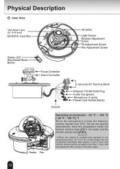
...{14 °F}, normal images may not be obtained immediately after turning on the power again. 12 In such a case, wait until the camera warms up (taking more than 1 hour) and start adjustment after startup. N.C. AACC2244VV General I/O Terminal Block Ethernet 10/100 RJ45 Plug Audio ... Ground Heater Fan Operating environment: -30 °C ~ +50 °C {-22 °F ~ 122 °F} *1 When the temparature inside the Network Camera drops to 0°C, the heater and fan will operate automatically; Physical Description Inner View Vari-focal Lens (f= 3~9 mm) SD/SDHC Card Slot IR LEDs...
...{14 °F}, normal images may not be obtained immediately after turning on the power again. 12 In such a case, wait until the camera warms up (taking more than 1 hour) and start adjustment after startup. N.C. AACC2244VV General I/O Terminal Block Ethernet 10/100 RJ45 Plug Audio ... Ground Heater Fan Operating environment: -30 °C ~ +50 °C {-22 °F ~ 122 °F} *1 When the temparature inside the Network Camera drops to 0°C, the heater and fan will operate automatically; Physical Description Inner View Vari-focal Lens (f= 3~9 mm) SD/SDHC Card Slot IR LEDs...

Quick Start Guide
Page 13
Outer View Camera Base Dome Cover Treat the dome cover with care when installing, Or it may be damaged. b 13 N.C. N.C. N.C. AC24V AC24V c b a Bottom Base c a Record the MAC address under 5678 the camera base before installing 714270 the camera. Hole a~c: Holes to secure the bottom base.
Outer View Camera Base Dome Cover Treat the dome cover with care when installing, Or it may be damaged. b 13 N.C. N.C. N.C. AC24V AC24V c b a Bottom Base c a Record the MAC address under 5678 the camera base before installing 714270 the camera. Hole a~c: Holes to secure the bottom base.

Quick Start Guide
Page 14
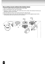
... into the corresponding holes and secure the bottom base with a screwdriver. 4. N.C. AC24V AC24V Ceiling mount (with the bottom base) 1. Secure the camera base to either a ceiling or a wall. A 1 2 4 B 5 3 14 N.C. Attach the supplied alignment sticker to loosen the three screws ...and detach the dome cover from the camera base. Hardware Installation First, use hole B, remove the rubber stopper with a screwdriver. 5. Feed the cables through hole A or B. If you want to...
... into the corresponding holes and secure the bottom base with a screwdriver. 4. N.C. AC24V AC24V Ceiling mount (with the bottom base) 1. Secure the camera base to either a ceiling or a wall. A 1 2 4 B 5 3 14 N.C. Attach the supplied alignment sticker to loosen the three screws ...and detach the dome cover from the camera base. Hardware Installation First, use hole B, remove the rubber stopper with a screwdriver. 5. Feed the cables through hole A or B. If you want to...

Quick Start Guide
Page 15
.... 3. If you want to the wall. 2. Attach the supplied alignment sticker to use hole B, remove the rubber stopper with three supplied screws. 1 3 2 4 A B 5 15 Secure the camera base to corresponding holes and secure the bottom base with the bottom base) 1. Feed the cables through hole A or B. Then hammer the four supplied plastic...
.... 3. If you want to the wall. 2. Attach the supplied alignment sticker to use hole B, remove the rubber stopper with three supplied screws. 1 3 2 4 A B 5 15 Secure the camera base to corresponding holes and secure the bottom base with the bottom base) 1. Feed the cables through hole A or B. Then hammer the four supplied plastic...
Quick Start Guide
Page 16
... the ceiling. 2. Attach the supplied ceiling hole template sticker to the ceiling and feed the cables through. 5. Open a hole along the inner circle of the camera base, insert the three supplied screws into the corresponding holes and secure them with a screwdriver. 5 4 1 2 3 Drill hole Ceiling Hole Template Sticker 16 plied plastic anchors...
... the ceiling. 2. Attach the supplied ceiling hole template sticker to the ceiling and feed the cables through. 5. Open a hole along the inner circle of the camera base, insert the three supplied screws into the corresponding holes and secure them with a screwdriver. 5 4 1 2 3 Drill hole Ceiling Hole Template Sticker 16 plied plastic anchors...
Quick Start Guide
Page 17
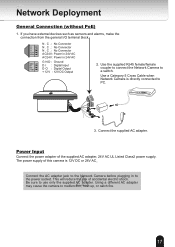
... No Connector AC24V AC24V AC24V: Power in 24V AC AC24V: Power in to PC. AC. Using a different AC adapter may cause the camera to a switch. A.C. If you have external devices such as sensors and alarms, make the connection from the general I : Digital Input ... No Connector N.C. C242V4V POWER COLLISION 1 2 3 4 5 LINK PARERCTIETIIVOEN 3. N.C. Use the supplied RJ45 female/female coupler to connect the Network Camera to malfunction, heat up, or catch fire. 17 Power Input Connect the power adapter of accidental electric shock. The power supply of this...
... No Connector AC24V AC24V AC24V: Power in 24V AC AC24V: Power in to PC. AC. Using a different AC adapter may cause the camera to a switch. A.C. If you have external devices such as sensors and alarms, make the connection from the general I : Digital Input ... No Connector N.C. C242V4V POWER COLLISION 1 2 3 4 5 LINK PARERCTIETIIVOEN 3. N.C. Use the supplied RJ45 female/female coupler to connect the Network Camera to malfunction, heat up, or catch fire. 17 Power Input Connect the power adapter of accidental electric shock. The power supply of this...
Quick Start Guide
Page 18
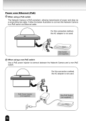
... a non-PoE switch Use a PoE power injector to a PoE switch via a single Ethernet cable. N.C. N.C. N.C. N.C. Follow the below illustration to connect the Network Camera to connect between the Network Camera and a non-PoE switch. N.C. For this connection method, the AC adapter is not used . For this connection method, the AC adapter is PoE...) POWER COLLISION 1 2 3 4 5 LINK RECEIVE PARTITION 18 NA.CC.24V AC24V POWER COLLISION 1 2 3 4 5 LINK RECEIVE PARTITION PoE Switch (not supplied) When using a PoE switch The Network Camera is not used .
... a non-PoE switch Use a PoE power injector to a PoE switch via a single Ethernet cable. N.C. N.C. N.C. N.C. Follow the below illustration to connect the Network Camera to connect between the Network Camera and a non-PoE switch. N.C. For this connection method, the AC adapter is not used . For this connection method, the AC adapter is PoE...) POWER COLLISION 1 2 3 4 5 LINK RECEIVE PARTITION 18 NA.CC.24V AC24V POWER COLLISION 1 2 3 4 5 LINK RECEIVE PARTITION PoE Switch (not supplied) When using a PoE switch The Network Camera is not used .
Quick Start Guide
Page 19
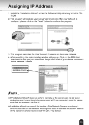
... "Installation Wizard" under the Software Utility directory from the product label of a PC. MAC:0002D1714270 00-02-D1-71-42-70 169.254.0.99 IK-WR12A 0002D1714270 NOTE l If "Installation Wizard" does not perform normally or the camera can search the location of the Network Camera has been set 169.254.*.* by default. 19
... "Installation Wizard" under the Software Utility directory from the product label of a PC. MAC:0002D1714270 00-02-D1-71-42-70 169.254.0.99 IK-WR12A 0002D1714270 NOTE l If "Installation Wizard" does not perform normally or the camera can search the location of the Network Camera has been set 169.254.*.* by default. 19
Quick Start Guide
Page 20
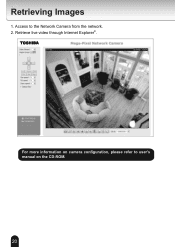
Access to user's manual on the CD-ROM. 20 Retrieve live video through Internet Explorer®. 2010/09/01 16:34:42 For more information on camera configuration, please refer to the Network Camera from the network. 2. Retrieving Images 1.
Access to user's manual on the CD-ROM. 20 Retrieve live video through Internet Explorer®. 2010/09/01 16:34:42 For more information on camera configuration, please refer to the Network Camera from the network. 2. Retrieving Images 1.

Quick Start Guide
Page 21
... lens module left and right. Upon completion, tighten screw. Loosen the tilt adjustment screws on the live image retrieved from the camera, adjust the camera lens by screw driver. Upon completion, tighten the focus controller. Upon completion, tighten the screws. 3. Loosen 1 Tighten Do ... The sophisticated 3-axis mechanism design offers very flexible, easy hardware installation for either ceiling or wall mount. Doing so will damage the camera lens module. 21 Upon completion, tighten the zoom controller. 2. Loosen the zoom controller to adjust the focus range. Loosen 2 Tighten...
... lens module left and right. Upon completion, tighten screw. Loosen the tilt adjustment screws on the live image retrieved from the camera, adjust the camera lens by screw driver. Upon completion, tighten the focus controller. Upon completion, tighten the screws. 3. Loosen 1 Tighten Do ... The sophisticated 3-axis mechanism design offers very flexible, easy hardware installation for either ceiling or wall mount. Doing so will damage the camera lens module. 21 Upon completion, tighten the zoom controller. 2. Loosen the zoom controller to adjust the focus range. Loosen 2 Tighten...

Quick Start Guide
Page 22
Attach the dome cover to fit the lens shooting direction. 2. Finally, make sure all parts of the camera are securely installed. 2 3 1 3 3 22 Rotate the black cover inside the dome cover to the camera. 3. Secure the three dome screws with the supplied hex key wrench. Completion 1.
Attach the dome cover to fit the lens shooting direction. 2. Finally, make sure all parts of the camera are securely installed. 2 3 1 3 3 22 Rotate the black cover inside the dome cover to the camera. 3. Secure the three dome screws with the supplied hex key wrench. Completion 1.
