Quick Start Guide
Page 1
NETWORK CAMERA Model: IK-WR12A Quick Start Guide and Important Safeguards This guide describes the hardware installation. Refer to the Toshiba website (http://www.toshiba.com). If you do not have this application, download it from the Adobe Systems Incorporated website. For information on our latest products and peripheral devices, refer to the following Website: n http://www.toshibasecurity.com If the URL changes, refer to the user's manual (PDF file) contained in the CD-ROM for settings, operations and other information. The application Adobe Reader is needed to view PDF files.
NETWORK CAMERA Model: IK-WR12A Quick Start Guide and Important Safeguards This guide describes the hardware installation. Refer to the Toshiba website (http://www.toshiba.com). If you do not have this application, download it from the Adobe Systems Incorporated website. For information on our latest products and peripheral devices, refer to the following Website: n http://www.toshibasecurity.com If the URL changes, refer to the user's manual (PDF file) contained in the CD-ROM for settings, operations and other information. The application Adobe Reader is needed to view PDF files.

Quick Start Guide
Page 2
...operated in which case the user will be voided if you make changes or modifications not expressly approved by the party. USER-INSTALLER CAUTION: Your authority to operate this device must accept any interference received, including interference that may cause undesired operation. This Class A digital apparatus complies with the instruction manual... complies with the limits for a Class A digital device, pursuant to Part 15 of the FCC Rules. Introduction FCC (USA)-INFORMATION NOTE: This equipment has been tested and found to comply with Part 15 of the FCC Rules. These limits are...
...operated in which case the user will be voided if you make changes or modifications not expressly approved by the party. USER-INSTALLER CAUTION: Your authority to operate this device must accept any interference received, including interference that may cause undesired operation. This Class A digital apparatus complies with the instruction manual... complies with the limits for a Class A digital device, pursuant to Part 15 of the FCC Rules. Introduction FCC (USA)-INFORMATION NOTE: This equipment has been tested and found to comply with Part 15 of the FCC Rules. These limits are...
Quick Start Guide
Page 3
... quick start guide may vary depending on the network environment. 3 Windows Vista®: Microsoft® Windows Vista® Business operating system -- l Other product names appearing in this quick start guide, keep it in this manual to indicate operating systems compatible with this quick start guide carefully to change without prior notice. Terms and Trademarks l The term "OS" is used in a convenient place for purchasing the IK-WR12A Network Camera...
... quick start guide may vary depending on the network environment. 3 Windows Vista®: Microsoft® Windows Vista® Business operating system -- l Other product names appearing in this quick start guide, keep it in this manual to indicate operating systems compatible with this quick start guide carefully to change without prior notice. Terms and Trademarks l The term "OS" is used in a convenient place for purchasing the IK-WR12A Network Camera...
Quick Start Guide
Page 4
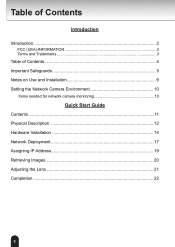
Table of Contents Introduction Introduction 2 FCC (USA)-INFORMATION 2 Terms and Trademarks 3 Table of Contents 4 Important Safeguards 5 Notes on Use and Installation 9 Setting the Network Camera Environment 10 Items needed for network camera monitoring 10 Quick Start Guide Contents 11 Physical Description 12 Hardware Installation 14 Network Deployment 17 Assigning IP Address 19 Retrieving Images 20 Adjusting the Lens 21 Completion 22 4
Table of Contents Introduction Introduction 2 FCC (USA)-INFORMATION 2 Terms and Trademarks 3 Table of Contents 4 Important Safeguards 5 Notes on Use and Installation 9 Setting the Network Camera Environment 10 Items needed for network camera monitoring 10 Quick Start Guide Contents 11 Physical Description 12 Hardware Installation 14 Network Deployment 17 Assigning IP Address 19 Retrieving Images 20 Adjusting the Lens 21 Completion 22 4
Quick Start Guide
Page 5
..., stand, tripod, bracket or table. Cleaning Disconnect this video product from the type of power source indicated on the product and in installation verify that the camera temperature operates within the recommended temperature range. 9. The video product may pose safety risks. 7. Ventilation This video product should never be operated only from the power supply before operating the product. 2. Attachments Do not use instructions. 5. If...
..., stand, tripod, bracket or table. Cleaning Disconnect this video product from the type of power source indicated on the product and in installation verify that the camera temperature operates within the recommended temperature range. 9. The video product may pose safety risks. 7. Ventilation This video product should never be operated only from the power supply before operating the product. 2. Attachments Do not use instructions. 5. If...

Quick Start Guide
Page 6
...Servicing Do not attempt to service this video product yourself as this video product on an unsecured location, the camera could result in a risk of time, unplug it from the wall outlet and disconnect the power supply and cable system. Pay particular attention to dangerous electrical or other hazards. Installation Install... Do not overload the power supply or extension cords as opening or removing covers may touch dangerous electrical points or short-out parts that they exit the product. 11. If installed on a secure part of any kind into this video product during a lightning storm...
...Servicing Do not attempt to service this video product yourself as this video product on an unsecured location, the camera could result in a risk of time, unplug it from the wall outlet and disconnect the power supply and cable system. Pay particular attention to dangerous electrical or other hazards. Installation Install... Do not overload the power supply or extension cords as opening or removing covers may touch dangerous electrical points or short-out parts that they exit the product. 11. If installed on a secure part of any kind into this video product during a lightning storm...
Quick Start Guide
Page 7
... adjustment of any service or repairs to this video product from the power supply and refer servicing to its normal operation. If the video product has been submerged in performance which indicates a need for service. 17. Safety Check Upon completion of other hazards. 18. When the power-supply cord or plug is in damage and will often require extensive work by the user's manual as the original part...
... adjustment of any service or repairs to this video product from the power supply and refer servicing to its normal operation. If the video product has been submerged in performance which indicates a need for service. 17. Safety Check Upon completion of other hazards. 18. When the power-supply cord or plug is in damage and will often require extensive work by the user's manual as the original part...

Quick Start Guide
Page 8
... to constitute a risk of important operating and maintenance (servicing) instructions in the literature accompanying the appliance. FIELD INSTALLATION MARKING: WORDED: "THIS INSTALLATION SHOULD BE MADE BY A QUALIFIED SERVICE PERSON AND SHOULD CONFORM TO ALL LOCAL CODES." 8 WARNING: TO REDUCE THE RISK OF FIRE OR ELECTRIC SHOCK, DO NOT SUBMERGE THIS CAMERA IN WATER. NO USER SERVICEABLE PARTS INSIDE. Important Safeguards (Cont...
... to constitute a risk of important operating and maintenance (servicing) instructions in the literature accompanying the appliance. FIELD INSTALLATION MARKING: WORDED: "THIS INSTALLATION SHOULD BE MADE BY A QUALIFIED SERVICE PERSON AND SHOULD CONFORM TO ALL LOCAL CODES." 8 WARNING: TO REDUCE THE RISK OF FIRE OR ELECTRIC SHOCK, DO NOT SUBMERGE THIS CAMERA IN WATER. NO USER SERVICEABLE PARTS INSIDE. Important Safeguards (Cont...
Quick Start Guide
Page 9
... parts specified. l Do not submerge in images. Special care is not a malfunction. l Should you notice any trouble If any trouble occurs while you continue to water (see IP rating), and can be used indoors or outdoors. Notes on the screen. l Treat the camera with the camera power off. If you are wired near electric lighting wires or a TV set, noise may appear on Use and Installation...
... parts specified. l Do not submerge in images. Special care is not a malfunction. l Should you notice any trouble If any trouble occurs while you continue to water (see IP rating), and can be used indoors or outdoors. Notes on the screen. l Treat the camera with the camera power off. If you are wired near electric lighting wires or a TV set, noise may appear on Use and Installation...
Quick Start Guide
Page 10
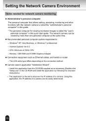
... setting, operating, monitoring and other functions with the network camera is called the "user's personal computer" in the CD-ROM and install the application by more than one personal computer at the same time. Internet Explorer Ver 8.0 -- Windows® XP, Vista Business, or Windows 7 professional. -- Memory: 1GB RAM and 512MB Graphics Adapter l Connection equipment such as an accessory (Double-click "Setup.exe" in this quick start guide...
... setting, operating, monitoring and other functions with the network camera is called the "user's personal computer" in the CD-ROM and install the application by more than one personal computer at the same time. Internet Explorer Ver 8.0 -- Windows® XP, Vista Business, or Windows 7 professional. -- Memory: 1GB RAM and 512MB Graphics Adapter l Connection equipment such as an accessory (Double-click "Setup.exe" in this quick start guide...
Quick Start Guide
Page 11
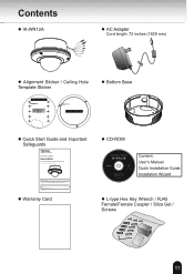
... the URL changes, refer to view PDF files. N.C. AACC2244VV l Alignment Sticker / Ceiling Hole Template Sticker l Bottom Base Drill hole Ceiling Hole Template Sticker l Quick Start Guide and Important Safeguards NETWORK CAMERA Model: IK-WR12A Quick Start Guide and Important Safeguards This guide describes the hardware installation. Contents l IK-WR12A l AC Adapter Cord length: 72 inches (1828 mm) N.C. The application Adobe Reader is needed to the Toshiba website (http://www.toshiba.com...
... the URL changes, refer to view PDF files. N.C. AACC2244VV l Alignment Sticker / Ceiling Hole Template Sticker l Bottom Base Drill hole Ceiling Hole Template Sticker l Quick Start Guide and Important Safeguards NETWORK CAMERA Model: IK-WR12A Quick Start Guide and Important Safeguards This guide describes the hardware installation. Contents l IK-WR12A l AC Adapter Cord length: 72 inches (1828 mm) N.C. The application Adobe Reader is needed to the Toshiba website (http://www.toshiba.com...
Quick Start Guide
Page 12
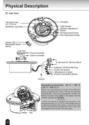
... Description Inner View Vari-focal Lens (f= 3~9 mm) SD/SDHC Card Slot IR LEDs Light Sensor Rotation Adjustment Screw Tilt Adjustment Screw Pan Adjustment Screw Status LED Reccessed Reset Button Focus Controller Zoom Controller N.C. N.C. AACC2244VV General I/O Terminal Block Ethernet 10/100 RJ45 Plug Audio Out (green) Microphone In (pink) Power Cord Socket (black) Ground Heater Fan Operating environment: -30 °C ~ +50 °C {-22 °F ~ 122 °F} *1 When the temparature inside the Network Camera drops to...
... Description Inner View Vari-focal Lens (f= 3~9 mm) SD/SDHC Card Slot IR LEDs Light Sensor Rotation Adjustment Screw Tilt Adjustment Screw Pan Adjustment Screw Status LED Reccessed Reset Button Focus Controller Zoom Controller N.C. N.C. AACC2244VV General I/O Terminal Block Ethernet 10/100 RJ45 Plug Audio Out (green) Microphone In (pink) Power Cord Socket (black) Ground Heater Fan Operating environment: -30 °C ~ +50 °C {-22 °F ~ 122 °F} *1 When the temparature inside the Network Camera drops to...

Quick Start Guide
Page 13
N.C. Hole a~c: Holes to secure the bottom base. N.C. b 13 N.C. Outer View Camera Base Dome Cover Treat the dome cover with care when installing, Or it may be damaged. AC24V AC24V c b a Bottom Base c a Record the MAC address under 5678 the camera base before installing 714270 the camera.
N.C. Hole a~c: Holes to secure the bottom base. N.C. b 13 N.C. Outer View Camera Base Dome Cover Treat the dome cover with care when installing, Or it may be damaged. AC24V AC24V c b a Bottom Base c a Record the MAC address under 5678 the camera base before installing 714270 the camera.

Quick Start Guide
Page 14
N.C. AC24V AC24V Ceiling mount (with a screwdriver. 4. Through the four holes on each side into the holes. 3. N.C. Secure the camera base to use a hex key wrench to all local codes. N.C. Feed the cables through hole A or B. If you want to the bottom base with a screwdriver. 5. Hardware Installation First, use hole B, remove the rubber stopper with three supplied screws. Using the 10 circles on the...
N.C. AC24V AC24V Ceiling mount (with a screwdriver. 4. Through the four holes on each side into the holes. 3. N.C. Secure the camera base to use a hex key wrench to all local codes. N.C. Feed the cables through hole A or B. If you want to the bottom base with a screwdriver. 5. Hardware Installation First, use hole B, remove the rubber stopper with three supplied screws. Using the 10 circles on the...

Quick Start Guide
Page 15
... symmetrically on the bottom base, insert the four supplied screws to the wall. 2. Feed the cables through hole A or B. Wall mount (with a screwdriver. 4. Using the four holes on each side into the holes. 3. Secure the camera base to use hole B, remove the rubber stopper with three supplied screws. 1 3 2 4 A B 5 15 Attach the supplied alignment sticker to corresponding holes and secure the bottom base with the bottom...
... symmetrically on the bottom base, insert the four supplied screws to the wall. 2. Feed the cables through hole A or B. Wall mount (with a screwdriver. 4. Using the four holes on each side into the holes. 3. Secure the camera base to use hole B, remove the rubber stopper with three supplied screws. 1 3 2 4 A B 5 15 Attach the supplied alignment sticker to corresponding holes and secure the bottom base with the bottom...
Quick Start Guide
Page 17
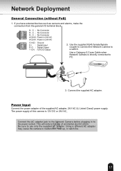
.... 17 NN.CN.C. Using a different AC adapter may cause the camera to a switch. N.C. N . Power Input Connect the power adapter of accidental electric shock. Network Deployment General Connection (without PoE) 1. AC. Connect the supplied AC adapter. If you have external devices such as sensors and alarms, make the connection from the general I : Digital Input DO +12V D O : Digital Output + 1 2 V : 12V DC Output 2. C242V4V POWER COLLISION 1 2 3 4 5 LINK PARERCTIETIIVOEN 3. The power supply of this camera is directly connected to PC.
.... 17 NN.CN.C. Using a different AC adapter may cause the camera to a switch. N.C. N . Power Input Connect the power adapter of accidental electric shock. Network Deployment General Connection (without PoE) 1. AC. Connect the supplied AC adapter. If you have external devices such as sensors and alarms, make the connection from the general I : Digital Input DO +12V D O : Digital Output + 1 2 V : 12V DC Output 2. C242V4V POWER COLLISION 1 2 3 4 5 LINK PARERCTIETIIVOEN 3. The power supply of this camera is directly connected to PC.
Quick Start Guide
Page 18
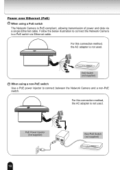
... PoE Power Injector (not supplied) Non-PoE Switch (not supplied) POWER COLLISION 1 2 3 4 5 LINK RECEIVE PARTITION 18 N.C. For this connection method, the AC adapter is not used . Follow the below illustration to connect the Network Camera to connect between the Network Camera and a non-PoE switch. N.C. Power over Ethernet (PoE) When using a non-PoE switch Use a PoE power injector to a PoE switch via a single Ethernet cable. NA.CC.24V AC24V POWER COLLISION 1 2 3 4 5 LINK RECEIVE PARTITION PoE Switch (not supplied) When using a PoE switch The Network Camera...
... PoE Power Injector (not supplied) Non-PoE Switch (not supplied) POWER COLLISION 1 2 3 4 5 LINK RECEIVE PARTITION 18 N.C. For this connection method, the AC adapter is not used . Follow the below illustration to connect the Network Camera to connect between the Network Camera and a non-PoE switch. N.C. Power over Ethernet (PoE) When using a non-PoE switch Use a PoE power injector to a PoE switch via a single Ethernet cable. NA.CC.24V AC24V POWER COLLISION 1 2 3 4 5 LINK RECEIVE PARTITION PoE Switch (not supplied) When using a PoE switch The Network Camera...
Quick Start Guide
Page 19
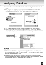
... though the camera and a PC are connected correctly, please switch off the wireless LAN of the Network Camera has been set 169.254.*.* by default. 19 Assigning IP Address 1. The program will pop up. After searching, the main installer window will analyze your network is not used on the "Next" button to the Network Camera. After your network environment. Reassign the static IP address because IP address of a PC. Installation Wizard 3.
... though the camera and a PC are connected correctly, please switch off the wireless LAN of the Network Camera has been set 169.254.*.* by default. 19 Assigning IP Address 1. The program will pop up. After searching, the main installer window will analyze your network is not used on the "Next" button to the Network Camera. After your network environment. Reassign the static IP address because IP address of a PC. Installation Wizard 3.
Quick Start Guide
Page 20
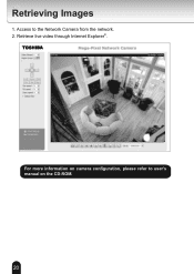
Retrieve live video through Internet Explorer®. 2010/09/01 16:34:42 For more information on the CD-ROM. 20 Access to user's manual on camera configuration, please refer to the Network Camera from the network. 2. Retrieving Images 1.
Retrieve live video through Internet Explorer®. 2010/09/01 16:34:42 For more information on the CD-ROM. 20 Access to user's manual on camera configuration, please refer to the Network Camera from the network. 2. Retrieving Images 1.

Quick Start Guide
Page 21
Loosen the tilt adjustment screws on the live image retrieved from the camera, adjust the camera lens by screw driver. Loosen the rotation adjustment screw and then turn the lens module up and down. Loosen 2 Tighten Loosen Tighten 3 Pan 350° Tilt 85° Rotate 350° To adjust the zoom factor and focus range 1. Loosen the focus controller to adjust the zoom factor. Loosen the pan adjustment screw and then turn the lens module left...
Loosen the tilt adjustment screws on the live image retrieved from the camera, adjust the camera lens by screw driver. Loosen the rotation adjustment screw and then turn the lens module up and down. Loosen 2 Tighten Loosen Tighten 3 Pan 350° Tilt 85° Rotate 350° To adjust the zoom factor and focus range 1. Loosen the focus controller to adjust the zoom factor. Loosen the pan adjustment screw and then turn the lens module left...
