Operation Manual
Page 1
NETWORK CAMERA Model: IK-WR01A Operation Manual To get started, read the separate "Safety Precautions" carefully. For information on the latest products and peripheral devices, refer to the firmware version R1.01 and later. This User's Guide applies to the following Web page. Ihttp://www.netcam.toshiba.com The above URL is subject to the Toshiba website (http://www.cctv.toshiba.com). WR01-01 If the URL changes, refer to change without prior notice.
NETWORK CAMERA Model: IK-WR01A Operation Manual To get started, read the separate "Safety Precautions" carefully. For information on the latest products and peripheral devices, refer to the firmware version R1.01 and later. This User's Guide applies to the following Web page. Ihttp://www.netcam.toshiba.com The above URL is subject to the Toshiba website (http://www.cctv.toshiba.com). WR01-01 If the URL changes, refer to change without prior notice.
Operation Manual
Page 3
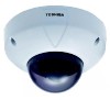
... FEATURES & DESCRIPTION 3 G Table of Contents 3 G Names and Features of View 8 G Installing the Camera Unit 11 • Installation to Wall or Ceiling with Mounting Base (Surface Mount Installation) ... 11 •...Camera Search Application "Camera Finder 24 GChanging Administrator Login ID and Password 26 GSetting up Access Restriction 28 GConfiguring the Network Manually 30 3 Setting up GINSTALLATION ...8 G Adjust the Angle of Parts 5 Installation/Set up Others AC24V or DC12V - Installation/Set up Viewing and Operation Recording INTRODUCTION FEATURES & DESCRIPTION IK-WR01A...
... FEATURES & DESCRIPTION 3 G Table of Contents 3 G Names and Features of View 8 G Installing the Camera Unit 11 • Installation to Wall or Ceiling with Mounting Base (Surface Mount Installation) ... 11 •...Camera Search Application "Camera Finder 24 GChanging Administrator Login ID and Password 26 GSetting up Access Restriction 28 GConfiguring the Network Manually 30 3 Setting up GINSTALLATION ...8 G Adjust the Angle of Parts 5 Installation/Set up Others AC24V or DC12V - Installation/Set up Viewing and Operation Recording INTRODUCTION FEATURES & DESCRIPTION IK-WR01A...

Operation Manual
Page 4
... Screen 35 • Menu that is displayed when right-clicking on the image 35 G Adjusting Images on the Camera 36 G Adding Images 38 GViewing Logs ...39 Recording GAbout Recording Images 42 GRecording Images on FTP Server 43 G Record Settings 43 • FTP ...Image 53 Setting up GHow to Set up ...56 G General Configuration 56 GSystem Settings 57 • Restoring the default settings 58 • Rebooting the network camera 59 • Updating the Firmware 59 • Click "Firmware update 59 • Importing the Settings Saved on a Personal Computer 59 GUser Settings ...60 GAdmin...
... Screen 35 • Menu that is displayed when right-clicking on the image 35 G Adjusting Images on the Camera 36 G Adding Images 38 GViewing Logs ...39 Recording GAbout Recording Images 42 GRecording Images on FTP Server 43 G Record Settings 43 • FTP ...Image 53 Setting up GHow to Set up ...56 G General Configuration 56 GSystem Settings 57 • Restoring the default settings 58 • Rebooting the network camera 59 • Updating the Firmware 59 • Click "Firmware update 59 • Importing the Settings Saved on a Personal Computer 59 GUser Settings ...60 GAdmin...

Operation Manual
Page 5
... to Page15) 5 "Optimum Value" is set values of the network camera are reset to obtain the best possible image. Line Lock Phase ADJ Adjusts the phase of power source input. RESET When the button is pressed, ... , it adjusts the backlight automatically to the default settings (initial stage). (→page.88) Viewing and Operation Recording Setting up Names and Features of the camera. Available only with the supplied monitor out harness wire. Lens Iris ADJ Counterclockwise: The picture becomes darker. Default switch is at default setting. Clockwise: The...
... to Page15) 5 "Optimum Value" is set values of the network camera are reset to obtain the best possible image. Line Lock Phase ADJ Adjusts the phase of power source input. RESET When the button is pressed, ... , it adjusts the backlight automatically to the default settings (initial stage). (→page.88) Viewing and Operation Recording Setting up Names and Features of the camera. Available only with the supplied monitor out harness wire. Lens Iris ADJ Counterclockwise: The picture becomes darker. Default switch is at default setting. Clockwise: The...

Operation Manual
Page 8
...Important Notice : Be sure to lose it. 8 Setting up Viewing and Operation Recording INSTALLATION G Connect the cable of View Security screws Top Cover a Camera Base Loosen the three security screws by the supplied special hexangular wrench and remove the top cover. NOTE • The weight... bracket weighs 5 lbs. Use appropriate screws. Installation/Set up Others Adjust the Angle of the camera and the cable from the designated power supply with the unit. G Screws for securing the camera and mounting base to the ceiling or wall are used only for transportation and must NOT be...
...Important Notice : Be sure to lose it. 8 Setting up Viewing and Operation Recording INSTALLATION G Connect the cable of View Security screws Top Cover a Camera Base Loosen the three security screws by the supplied special hexangular wrench and remove the top cover. NOTE • The weight... bracket weighs 5 lbs. Use appropriate screws. Installation/Set up Others Adjust the Angle of the camera and the cable from the designated power supply with the unit. G Screws for securing the camera and mounting base to the ceiling or wall are used only for transportation and must NOT be...

Operation Manual
Page 10
Repeat the adjustments from step 1 to adjust the inclination of the image. When installing the camera on a wall, manipulate the horizontal adjustment ring 4 to step 6 until the optimum image appears. 10 Setting up Viewing and Operation Recording INSTALLATION (Cont.) The lens ...
Repeat the adjustments from step 1 to adjust the inclination of the image. When installing the camera on a wall, manipulate the horizontal adjustment ring 4 to step 6 until the optimum image appears. 10 Setting up Viewing and Operation Recording INSTALLATION (Cont.) The lens ...

Operation Manual
Page 11
...(sideway) D Rear cable hole In case of using the Drain groove variable mounting holes Recording Setting up Viewing and Operation Installing the Camera Unit I Installation to Wall or Ceiling with Mounting Base (Surface Mount Installation) Unit: mm (inches) • When installing the...screws using the supplied special hexangular wrench. Top Cover Align to this mark. 11 Do not block the drain groove. • When installing the camera unit outdoor, waterproof the cables. Mount the top cover (dome cover assembly) and secure it with the drain groove on the downside. Installation/...
...(sideway) D Rear cable hole In case of using the Drain groove variable mounting holes Recording Setting up Viewing and Operation Installing the Camera Unit I Installation to Wall or Ceiling with Mounting Base (Surface Mount Installation) Unit: mm (inches) • When installing the...screws using the supplied special hexangular wrench. Top Cover Align to this mark. 11 Do not block the drain groove. • When installing the camera unit outdoor, waterproof the cables. Mount the top cover (dome cover assembly) and secure it with the drain groove on the downside. Installation/...

Operation Manual
Page 12
Screws x3 Mount camera base with three security screws using the supplied special hexangular wrench. Align the marks. Mount the top cover (dome cover assembly) and secure it firmly ... the screw mounts on the bracket. Recording Setting up Viewing and Operation INSTALLATION (Cont.) I Installation to this mark. 12 The convex side should face the camera base.
Screws x3 Mount camera base with three security screws using the supplied special hexangular wrench. Align the marks. Mount the top cover (dome cover assembly) and secure it firmly ... the screw mounts on the bracket. Recording Setting up Viewing and Operation INSTALLATION (Cont.) I Installation to this mark. 12 The convex side should face the camera base.
Operation Manual
Page 14
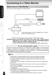
... be connected to a power supply that the PoE/POWER SELECT switch is turned on the video monitor. G For details of wiring and operation of the camera. G Coaxial cables for at the same time. G Use IEEE802.3af-compliant PoE devices. G A 75-ohm coaxial cable (3C-2V or 5C-2V)... of DC12V, connect "+12" to red cable and "GND" to black cable. Because the IK-WR01A uses a mechanism, a sufficient power supply with adequate current specifications is required for the LAN cable to connect the camera to a PoE compatible hub. G Do not connect AC24V and DC12V at the same time. ...
... be connected to a power supply that the PoE/POWER SELECT switch is turned on the video monitor. G For details of wiring and operation of the camera. G Coaxial cables for at the same time. G Use IEEE802.3af-compliant PoE devices. G A 75-ohm coaxial cable (3C-2V or 5C-2V)... of DC12V, connect "+12" to red cable and "GND" to black cable. Because the IK-WR01A uses a mechanism, a sufficient power supply with adequate current specifications is required for the LAN cable to connect the camera to a PoE compatible hub. G Do not connect AC24V and DC12V at the same time. ...
Operation Manual
Page 15
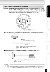
...NOT RE-SET THE POWER SELECTION SWITCH WHEN THE UNIT IS ON. Ensure that the POWER SELECT switch is properly set before turning the camera on the camera to the correct power source before inputting power. 15 Others Installation/Set up POWER SELECT Switch s When power is supplied from an ...AC24V/ PoE DC12V Switch the POWER SELECT switch to AC24V/DC12V. Viewing and Operation Recording Setting up About the POWER SELECT Switch CAUTION : The IK-WR01A operates with one of the following power source: 12vDC, 24vAC or PoE. s When power is supplied from a PoE compatible hub, etc.
...NOT RE-SET THE POWER SELECTION SWITCH WHEN THE UNIT IS ON. Ensure that the POWER SELECT switch is properly set before turning the camera on the camera to the correct power source before inputting power. 15 Others Installation/Set up POWER SELECT Switch s When power is supplied from an ...AC24V/ PoE DC12V Switch the POWER SELECT switch to AC24V/DC12V. Viewing and Operation Recording Setting up About the POWER SELECT Switch CAUTION : The IK-WR01A operates with one of the following power source: 12vDC, 24vAC or PoE. s When power is supplied from a PoE compatible hub, etc.

Operation Manual
Page 16
G When two or more cameras are switched by video switcher for viewing by a monitor TV, the vertical sync. phase can be locked with the power frequency is on. Recording Setting ...
G When two or more cameras are switched by video switcher for viewing by a monitor TV, the vertical sync. phase can be locked with the power frequency is on. Recording Setting ...

Operation Manual
Page 17
...is synchronized to the power frequency of 60±1 Hz covering a normal fluctuation of each camera. Line Lock V PHASE CONTROL NOTE G The camera is normal, because several seconds are required to stabilize the camera against power noise. 17 Setting up Viewing and Operation Recording I LINE LOCK PHASE When ...until a stable synchronization is obtained after the power is turned on the video monitor due to get a stable image. However, the camera may fluctuate on . In this case, adjust the V PHASE controller to the different AC line phase of the power frequency. Installation/Set...
...is synchronized to the power frequency of 60±1 Hz covering a normal fluctuation of each camera. Line Lock V PHASE CONTROL NOTE G The camera is normal, because several seconds are required to stabilize the camera against power noise. 17 Setting up Viewing and Operation Recording I LINE LOCK PHASE When ...until a stable synchronization is obtained after the power is turned on the video monitor due to get a stable image. However, the camera may fluctuate on . In this case, adjust the V PHASE controller to the different AC line phase of the power frequency. Installation/Set...

Operation Manual
Page 18
Mode Setting Switch BLC ON OFF BLC Switch Viewing and Operation Recording Setting up Adjusting a Lens Back Light Compensation By turning on the back light compensation switch, the camera controls the back light automatically to page 37. For setting the metering area of back light compensation, refer to ensure proper exposure in the specified area when using an auto iris lens or fixed iris lens with the "AES" mode. Installation/Set up Others 18
Mode Setting Switch BLC ON OFF BLC Switch Viewing and Operation Recording Setting up Adjusting a Lens Back Light Compensation By turning on the back light compensation switch, the camera controls the back light automatically to page 37. For setting the metering area of back light compensation, refer to ensure proper exposure in the specified area when using an auto iris lens or fixed iris lens with the "AES" mode. Installation/Set up Others 18

Operation Manual
Page 19
Auto White Balance (AWB) The camera has an auto white balance capability in contrast between the subject and the surrounding (e.g. when the background is a large difference in the range of 2,500K to 10,000K color temperature of light. 19 Setting up Others Installation/Set up Viewing and Operation Recording NOTE G When there is extremely bright), the BLC effect may be limited.
Auto White Balance (AWB) The camera has an auto white balance capability in contrast between the subject and the surrounding (e.g. when the background is a large difference in the range of 2,500K to 10,000K color temperature of light. 19 Setting up Others Installation/Set up Viewing and Operation Recording NOTE G When there is extremely bright), the BLC effect may be limited.

Operation Manual
Page 20
...system environment • The type of Connection" (➝ page. 22). ° Install the camera search application ("Camera Finder") Install the application from a single network camera. Installation/Set up Others Multiple user's personal computers can monitor images from the supplied CD-ROM (&#...10141; page. 24). 20 Setting up Viewing and Operation Recording Setting Up the Network Camera Environment Requirements for Network Camera Monitoring System ° Administrator's personal computer This manual refers to a personal computer that is used . System ...
...system environment • The type of Connection" (➝ page. 22). ° Install the camera search application ("Camera Finder") Install the application from a single network camera. Installation/Set up Others Multiple user's personal computers can monitor images from the supplied CD-ROM (&#...10141; page. 24). 20 Setting up Viewing and Operation Recording Setting Up the Network Camera Environment Requirements for Network Camera Monitoring System ° Administrator's personal computer This manual refers to a personal computer that is used . System ...
Operation Manual
Page 21
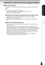
...procedure for entering an IP address manually, refer to "Configuring the Network Manually" (➝ page. 30). 21 Setting up Viewing and Operation Recording Connecting the Camera and Personal Computer by Network IAbout the IP Address To connect to the network, the administrator needs to obtain an IP address automatically from the...setting is using DHCP server, keep the setting as "Automatically by the DHCP server. If your network is "Automatically by manually setting) in the network camera. Therefore, the previous IP address may be valid, not allowing you need to set the network...
...procedure for entering an IP address manually, refer to "Configuring the Network Manually" (➝ page. 30). 21 Setting up Viewing and Operation Recording Connecting the Camera and Personal Computer by Network IAbout the IP Address To connect to the network, the administrator needs to obtain an IP address automatically from the...setting is using DHCP server, keep the setting as "Automatically by the DHCP server. If your network is "Automatically by manually setting) in the network camera. Therefore, the previous IP address may be valid, not allowing you need to set the network...

Operation Manual
Page 22
...port of your computer's user's guide. Others 22 When using a hub. G Establishing a connection via a hub or router (example) Network camera IP address 192.168.0.30 Internet Hub or router Personal computer IP address 192.168.0.50 LAN cable (straight through) LAN cable (straight through...) Recording Setting up Viewing and Operation Connecting the Camera and Personal Computer by default. G In the case of not using a broadband router, if the "Connections Settings" is also recommended ...
...port of your computer's user's guide. Others 22 When using a hub. G Establishing a connection via a hub or router (example) Network camera IP address 192.168.0.30 Internet Hub or router Personal computer IP address 192.168.0.50 LAN cable (straight through) LAN cable (straight through...) Recording Setting up Viewing and Operation Connecting the Camera and Personal Computer by default. G In the case of not using a broadband router, if the "Connections Settings" is also recommended ...

Operation Manual
Page 23
...correctly established. http://192.168.0.30:88/). G Set the IP address of the computer to the user's guide of the personal computer. d) The Camera Window screen appears. NOTE G To view the screen without using a PoE compatible hub, connect AC24V or DC12V power plug with the powered personal computer...press ENTER. G If the "Reply from the personal computer. Connect the LAN cable (straight) leading to select. • Check that the camera name, the IP address and the HTTP port number are displayed in the login field of the personal computer. message appears, the connection is ...
...correctly established. http://192.168.0.30:88/). G Set the IP address of the computer to the user's guide of the personal computer. d) The Camera Window screen appears. NOTE G To view the screen without using a PoE compatible hub, connect AC24V or DC12V power plug with the powered personal computer...press ENTER. G If the "Reply from the personal computer. Connect the LAN cable (straight) leading to select. • Check that the camera name, the IP address and the HTTP port number are displayed in the login field of the personal computer. message appears, the connection is ...
Operation Manual
Page 24
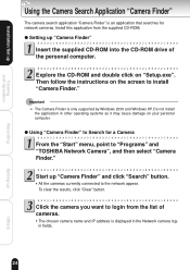
...-ROM and double click on the screen to "Programs" and "TOSHIBA Network Camera", and then select "Camera Finder." G The chosen camera name and IP address is only supported by Windows 2000 and Windows XP. Installation/Set up "Camera Finder" and click "Search" button. G All the cameras currently connected to login from the supplied CD-ROM. Click...
...-ROM and double click on the screen to "Programs" and "TOSHIBA Network Camera", and then select "Camera Finder." G The chosen camera name and IP address is only supported by Windows 2000 and Windows XP. Installation/Set up "Camera Finder" and click "Search" button. G All the cameras currently connected to login from the supplied CD-ROM. Click...

Operation Manual
Page 25
... window without logging in Click "Exit" button to close "Camera Finder" Important G Toshiba is invalid for any damages caused by this software. G The browser starts up access restrictions (➝ page. 28). 25 Others G When you log in the "Camera Finder" is not responsible for the IK-WR01A. G The "Administrator" button in as Administrator, set up...
... window without logging in Click "Exit" button to close "Camera Finder" Important G Toshiba is invalid for any damages caused by this software. G The browser starts up access restrictions (➝ page. 28). 25 Others G When you log in the "Camera Finder" is not responsible for the IK-WR01A. G The "Administrator" button in as Administrator, set up...
