Maintenance Manual
Page 13
... Mask...4-53 Removing the 15.4-inch LCD Display Mask 4-53 Installing the 15.4-inch LCD Display Mask 4-54 4.15 FL Inverter Board 4-55 Removing the FL Inverter Board 4-55 Installing the FL Inverter Board 4-56 4.16 LCD Modules ...4-57 Removing the 15.4-inch LCD module 4-57 Installing the 15.4-inch LCD Module 4-59... Touch Pad Board 4-66 Removing the Touch Pad and Touch Pad Board (For Commercial Model 4-67 Installing the Touch Pad and Touch Pad Board 4-68 Satellite A100/A105 / TECRA A7 Maintenance Manual xiii
... Mask...4-53 Removing the 15.4-inch LCD Display Mask 4-53 Installing the 15.4-inch LCD Display Mask 4-54 4.15 FL Inverter Board 4-55 Removing the FL Inverter Board 4-55 Installing the FL Inverter Board 4-56 4.16 LCD Modules ...4-57 Removing the 15.4-inch LCD module 4-57 Installing the 15.4-inch LCD Module 4-59... Touch Pad Board 4-66 Removing the Touch Pad and Touch Pad Board (For Commercial Model 4-67 Installing the Touch Pad and Touch Pad Board 4-68 Satellite A100/A105 / TECRA A7 Maintenance Manual xiii

Maintenance Manual
Page 61
...of the cables is detected in the test, go to Procedure 3. If the external monitor appears to the system board and FL inverter board. Go to the computer's external monitor port, then boot the computer. If there is defective or malfunctioning, follow the troubleshooting ... board may be faulty. 2 Troubleshooting 2.7 Display 2.7 Display To check if the computer's display is still an error, perform Check 3. 2-18 Satellite A100/A105 / TECRA A7 Maintenance Manual If the external monitor works correctly, the internal LCD, LCD/FL cable, or FL may be defective. Go to ...
...of the cables is detected in the test, go to Procedure 3. If the external monitor appears to the system board and FL inverter board. Go to the computer's external monitor port, then boot the computer. If there is defective or malfunctioning, follow the troubleshooting ... board may be faulty. 2 Troubleshooting 2.7 Display 2.7 Display To check if the computer's display is still an error, perform Check 3. 2-18 Satellite A100/A105 / TECRA A7 Maintenance Manual If the external monitor works correctly, the internal LCD, LCD/FL cable, or FL may be defective. Go to ...

Maintenance Manual
Page 62
...perform Check 10. Make sure the LCD/FL cable has been firmly connected to Procedure 3. The LCD/FL inverter cable may be faulty. The LCD module may be faulty. The FL inverter board may be faulty. If there is still an error, perform Check 8. Replace it with a new ... to Procedure 3. The CPU may be faulty. FL inverter board System board CPU Check 6 Check 7 Check 8 Check 9 Check 10 LCD/FL cable If the cable is loose or off, reconnect it with a new one and return to Procedure 3. Satellite A100/A105 / TECRA A7 Maintenance Manual 2-19 Replace it with ...
...perform Check 10. Make sure the LCD/FL cable has been firmly connected to Procedure 3. The LCD/FL inverter cable may be faulty. The LCD module may be faulty. The FL inverter board may be faulty. If there is still an error, perform Check 8. Replace it with a new ... to Procedure 3. The CPU may be faulty. FL inverter board System board CPU Check 6 Check 7 Check 8 Check 9 Check 10 LCD/FL cable If the cable is loose or off, reconnect it with a new one and return to Procedure 3. Satellite A100/A105 / TECRA A7 Maintenance Manual 2-19 Replace it with ...

Maintenance Manual
Page 150
... Mask...4-53 Removing the 15.4-inch LCD Display Mask 4-53 Installing the 15.4-inch LCD Display Mask 4-54 4.15 FL Inverter Board...4-55 Removing the FL Inverter Board 4-55 Installing the FL Inverter Board 4-56 4.16 LCD Modules...4-57 Removing the 15.4-inch LCD module 4-57 Installing the 15.4-inch LCD Module 4-59... Touch Pad Board 4-66 Removing the Touch Pad and Touch Pad Board (For Commercial Model 4-67 Installing the Touch Pad and Touch Pad Board 4-68 Satellite A100/A105 / TECRA A7 Maintenance Manual 4-v
... Mask...4-53 Removing the 15.4-inch LCD Display Mask 4-53 Installing the 15.4-inch LCD Display Mask 4-54 4.15 FL Inverter Board...4-55 Removing the FL Inverter Board 4-55 Installing the FL Inverter Board 4-56 4.16 LCD Modules...4-57 Removing the 15.4-inch LCD module 4-57 Installing the 15.4-inch LCD Module 4-59... Touch Pad Board 4-66 Removing the Touch Pad and Touch Pad Board (For Commercial Model 4-67 Installing the Touch Pad and Touch Pad Board 4-68 Satellite A100/A105 / TECRA A7 Maintenance Manual 4-v
Maintenance Manual
Page 152
... print board and print board 4-49 Figure 4-32 Removing the system board 4-51 Figure 4-33 Removing the display mask 4-53 Figure 4-34 Removing the FL inverter board 4-55 Figure 4-35 Removing the 15.4-inch LCD module and screws 4-57 Figure 4-36 Removing the 15.4-inch LCD module 4-58 Figure 4-37 Removing... Removing the switch board 4-63 Figure 4-41 Removing the touch pad and button board 4-65 Figure 4-42 Removing the touch pad and button board 4-67 Satellite A100/A105 / TECRA A7 Maintenance Manual 4-vii
... print board and print board 4-49 Figure 4-32 Removing the system board 4-51 Figure 4-33 Removing the display mask 4-53 Figure 4-34 Removing the FL inverter board 4-55 Figure 4-35 Removing the 15.4-inch LCD module and screws 4-57 Figure 4-36 Removing the 15.4-inch LCD module 4-58 Figure 4-37 Removing... Removing the switch board 4-63 Figure 4-41 Removing the touch pad and button board 4-65 Figure 4-42 Removing the touch pad and button board 4-67 Satellite A100/A105 / TECRA A7 Maintenance Manual 4-vii

Maintenance Manual
Page 153
The FRUs shown in the top area of the chart should be removed before removing the suspect FRU. After you to replace only one FRU. Satellite A100/A105 / TECRA A7 Maintenance Manual 4-1 To replace the FRUs, first identify the suspect FRU for the system failure. The chart below shows the FRUs... to be removed before removing the FRUs shown in the bottom area. For removing the LCD Module: First, remove the display mask and FL inverter board, both of which are shown above the top cover with the display assembly. Next, according to this chart, determine the FRUs that need...
The FRUs shown in the top area of the chart should be removed before removing the suspect FRU. After you to replace only one FRU. Satellite A100/A105 / TECRA A7 Maintenance Manual 4-1 To replace the FRUs, first identify the suspect FRU for the system failure. The chart below shows the FRUs... to be removed before removing the FRUs shown in the bottom area. For removing the LCD Module: First, remove the display mask and FL inverter board, both of which are shown above the top cover with the display assembly. Next, according to this chart, determine the FRUs that need...

Maintenance Manual
Page 155
... 4 Replacement Procedures Safety Precautions Before you begin to remove any metal jewelry or accessories such as the power supply and FL inverter carry high voltages. Never throw the battery packs into a fire. Because the battery in specifications and are working. To avoid...disassemble individual components during first-level maintenance. The components such as necklaces, bracelets, and rings before starting work with the computer. Satellite A100/A105 / TECRA A7 Maintenance Manual 4-3 DANGER: 1. To avoid the risk of electrical shock. WARNING: 1. Be sure to avoid...
... 4 Replacement Procedures Safety Precautions Before you begin to remove any metal jewelry or accessories such as the power supply and FL inverter carry high voltages. Never throw the battery packs into a fire. Because the battery in specifications and are working. To avoid...disassemble individual components during first-level maintenance. The components such as necklaces, bracelets, and rings before starting work with the computer. Satellite A100/A105 / TECRA A7 Maintenance Manual 4-3 DANGER: 1. To avoid the risk of electrical shock. WARNING: 1. Be sure to avoid...
Maintenance Manual
Page 208
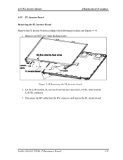
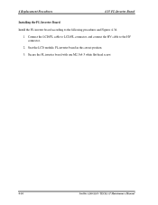
Figure 4-34 Removing the FL inverter board 2. Disconnect the HV cable from the LCD/FL connector. 3. Lift the LCD module, FL inverter board and disconnect the LCD/FL cable from the HV connector and remove the FL inverter board. 4.15 FL Inverter Board 4 Replacement Procedures 4.15 FL Inverter Board Removing the FL Inverter Board Remove the FL inverter board according to the following procedures and Figures 4-34. 1. Satellite A100/A105 / TECRA A7 Maintenance Manual 4-55 Remove one M2.5x4.5 white flat-head screw.
Figure 4-34 Removing the FL inverter board 2. Disconnect the HV cable from the LCD/FL connector. 3. Lift the LCD module, FL inverter board and disconnect the LCD/FL cable from the HV connector and remove the FL inverter board. 4.15 FL Inverter Board 4 Replacement Procedures 4.15 FL Inverter Board Removing the FL Inverter Board Remove the FL inverter board according to the following procedures and Figures 4-34. 1. Satellite A100/A105 / TECRA A7 Maintenance Manual 4-55 Remove one M2.5x4.5 white flat-head screw.
Maintenance Manual
Page 209
Seat the LCD module, FL inverter board in the correct position. 3. Connect the LCD/FL cable to LCD/FL connector, and connect the HV cable to the following procedures and Figures 4-34. 1. 4 Replacement Procedures 4.15 FL Inverter Board Installing the FL Inverter Board Install the FL inverter board according to the HV connector. 2. Secure the FL inverter board with one M2.5x4.5 white flat-head screw. 4-56 Satellite A100/A105 / TECRA A7 Maintenance Manual
Seat the LCD module, FL inverter board in the correct position. 3. Connect the LCD/FL cable to LCD/FL connector, and connect the HV cable to the following procedures and Figures 4-34. 1. 4 Replacement Procedures 4.15 FL Inverter Board Installing the FL Inverter Board Install the FL inverter board according to the HV connector. 2. Secure the FL inverter board with one M2.5x4.5 white flat-head screw. 4-56 Satellite A100/A105 / TECRA A7 Maintenance Manual
Maintenance Manual
Page 224
...Front View B-1 B.2 System Board Back View B-3 Appendix C...C-3 Appendix C Error! C.1 CN1 RJ45 Cable Connector (12-Pin C-3 C.2 CN2 USB Port0/Port1 Connector (8-Pin C-3 C.3 CN3 LCD/FL Inverter Connector (40-Pin C-3 C.4 CN4 CRT Connector (15-Pin C-4 C.5 CN5 Internal Left Speaker Connector (4-Pin C-4 C.6 CN6 Battery Connector (7-Pin C-5 C.7 CN7 Parallel/B Connector(20-Pin C-5 ...11 C.17 CN18 Stick Point Connector (8-Pin C-12 C.18 CN19 Mini PCI Connector (52-Pin C-12 C.19 CN20 ODD Connector (50-Pin C-13 Satellite A100/A105 / TECRA A7 Maintenance Manual App-iii Bookmark not defined.
...Front View B-1 B.2 System Board Back View B-3 Appendix C...C-3 Appendix C Error! C.1 CN1 RJ45 Cable Connector (12-Pin C-3 C.2 CN2 USB Port0/Port1 Connector (8-Pin C-3 C.3 CN3 LCD/FL Inverter Connector (40-Pin C-3 C.4 CN4 CRT Connector (15-Pin C-4 C.5 CN5 Internal Left Speaker Connector (4-Pin C-4 C.6 CN6 Battery Connector (7-Pin C-5 C.7 CN7 Parallel/B Connector(20-Pin C-5 ...11 C.17 CN18 Stick Point Connector (8-Pin C-12 C.18 CN19 Mini PCI Connector (52-Pin C-12 C.19 CN20 ODD Connector (50-Pin C-13 Satellite A100/A105 / TECRA A7 Maintenance Manual App-iii Bookmark not defined.


