
Maintenance Manual
Page 5
Handling the LCD module ? Keyboard scan/character codes ? BIOS Rewrite Procedures Satellite A100/A105 / TECRA A7 Maintenance Manual v Appendices The appendices describe the following parts: Chapter 1 Hardware Overview describes the Satellite A100/A105 / TECRA A7 system unit and each FRU. Wiring diagrams ? The manual is divided into the following : ? Chapter 4 Replacement Procedures describes the removal and replacement of...
Handling the LCD module ? Keyboard scan/character codes ? BIOS Rewrite Procedures Satellite A100/A105 / TECRA A7 Maintenance Manual v Appendices The appendices describe the following parts: Chapter 1 Hardware Overview describes the Satellite A100/A105 / TECRA A7 system unit and each FRU. Wiring diagrams ? The manual is divided into the following : ? Chapter 4 Replacement Procedures describes the removal and replacement of...

Maintenance Manual
Page 61
..., perform Check 5. (3) If the FL remains lit when the display is still an error, perform Check 3. 2-18 Satellite A100/A105 / TECRA A7 Maintenance Manual Replace it firmly and return to the system board and FL inverter board. Go to Procedure 3. Disassemble the computer following the ...monitor to Procedure 2. Go to the computer's external monitor port, then boot the computer. Procedure 3 Connector Check and Replacement Check The display unit has an LCD module, Fluorescent lamp (FL), panel close switch may be faulty. If there is defective or malfunctioning, follow the ...
..., perform Check 5. (3) If the FL remains lit when the display is still an error, perform Check 3. 2-18 Satellite A100/A105 / TECRA A7 Maintenance Manual Replace it firmly and return to the system board and FL inverter board. Go to Procedure 3. Disassemble the computer following the ...monitor to Procedure 2. Go to the computer's external monitor port, then boot the computer. Procedure 3 Connector Check and Replacement Check The display unit has an LCD module, Fluorescent lamp (FL), panel close switch may be faulty. If there is defective or malfunctioning, follow the ...

Maintenance Manual
Page 62
... firmly and return to the system board and LCD module. The FL inverter board may be defective. If there is still an error, perform Check 9. If there is still an error, perform Check 8. Satellite A100/A105 / TECRA A7 Maintenance Manual 2-19 Replace it with a new one . If there is... still an error, perform Check 7. If there is still an error, perform Check 4. The LCD module may be faulty. The memory may be faulty. The...
... firmly and return to the system board and LCD module. The FL inverter board may be defective. If there is still an error, perform Check 9. If there is still an error, perform Check 8. Satellite A100/A105 / TECRA A7 Maintenance Manual 2-19 Replace it with a new one . If there is... still an error, perform Check 7. If there is still an error, perform Check 4. The LCD module may be faulty. The memory may be faulty. The...
Maintenance Manual
Page 142
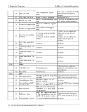
...Port No external fixtures on LPT port. 3 Diagnostic Programs 3.11Error Codes and Description 16 AGP Test Error 17 LCD Panel Test Error AGP configuration register errors. Replace the LCD. 19 Register Test Error Physical problems with the video Check and see whether the monitor has any physic al... problem. As above . 31xx Audio 01 Audio Play Fail Cannot play music. Check the the test. As above . 66 Satellite A100/A105 / TECRA A7...
...Port No external fixtures on LPT port. 3 Diagnostic Programs 3.11Error Codes and Description 16 AGP Test Error 17 LCD Panel Test Error AGP configuration register errors. Replace the LCD. 19 Register Test Error Physical problems with the video Check and see whether the monitor has any physic al... problem. As above . 31xx Audio 01 Audio Play Fail Cannot play music. Check the the test. As above . 66 Satellite A100/A105 / TECRA A7...

Maintenance Manual
Page 150
4 Replacement Procedures Removing the USB Board, Finger Print Board and Print Board 4-49 Installing the USB Board, Finger Print Board ...FL Inverter Board...4-55 Removing the FL Inverter Board 4-55 Installing the FL Inverter Board 4-56 4.16 LCD Modules...4-57 Removing the 15.4-inch LCD module 4-57 Installing the 15.4-inch LCD Module 4-59 4.17 Speakers ...4-60 Removing the Speakers 4-60 Installing the Speakers 4-60 4.18 Switch ... Touch Pad and Touch Pad Board (For Commercial Model 4-67 Installing the Touch Pad and Touch Pad Board 4-68 Satellite A100/A105 / TECRA A7 Maintenance Manual 4-v
4 Replacement Procedures Removing the USB Board, Finger Print Board and Print Board 4-49 Installing the USB Board, Finger Print Board ...FL Inverter Board...4-55 Removing the FL Inverter Board 4-55 Installing the FL Inverter Board 4-56 4.16 LCD Modules...4-57 Removing the 15.4-inch LCD module 4-57 Installing the 15.4-inch LCD Module 4-59 4.17 Speakers ...4-60 Removing the Speakers 4-60 Installing the Speakers 4-60 4.18 Switch ... Touch Pad and Touch Pad Board (For Commercial Model 4-67 Installing the Touch Pad and Touch Pad Board 4-68 Satellite A100/A105 / TECRA A7 Maintenance Manual 4-v
Maintenance Manual
Page 152
... LCD module 4-58 Figure 4-37 Removing the speakers 4-60 Figure 4-38 Removing the switch cover 4-61 Figure 4-39 Removing the switch board 4-62 Figure 4-40 Removing the switch board 4-63 Figure 4-41 Removing the touch pad and button board 4-65 Figure 4-42 Removing the touch pad and button board 4-67 Satellite A100/A105...
... LCD module 4-58 Figure 4-37 Removing the speakers 4-60 Figure 4-38 Removing the switch cover 4-61 Figure 4-39 Removing the switch board 4-62 Figure 4-40 Removing the switch board 4-63 Figure 4-41 Removing the touch pad and button board 4-65 Figure 4-42 Removing the touch pad and button board 4-67 Satellite A100/A105...

Maintenance Manual
Page 153
...removed in the bottom area. Then start removal and replacement How to disassemble the computer and replace Field Replaceable Units (FRUs). To replace the FRUs, first identify the suspect FRU for the system failure. For removing the LCD Module: First, remove the display mask and FL ...two examples): ? The chart below shows the FRUs in the order in which are shown above the LCD module. Satellite A100/A105 / TECRA A7 Maintenance Manual 4-1 Some replacement procedures may not require you determine those FRUs, go to the appropriate sections according to be removed before...
...removed in the bottom area. Then start removal and replacement How to disassemble the computer and replace Field Replaceable Units (FRUs). To replace the FRUs, first identify the suspect FRU for the system failure. For removing the LCD Module: First, remove the display mask and FL ...two examples): ? The chart below shows the FRUs in the order in which are shown above the LCD module. Satellite A100/A105 / TECRA A7 Maintenance Manual 4-1 Some replacement procedures may not require you determine those FRUs, go to the appropriate sections according to be removed before...

Maintenance Manual
Page 187
... LCD/FL cable from the top cover. 6. Remove the wireless antenna cables from CN3 on the system board. 4. Remove the display module. 4-34 Satellite A100/A105 / TECRA A7 Maintenance Manual Remove the display assembly according to avoid that the antenna cable is facing you and remove two M2.5x5 black flat-head screws. 2. 4 Replacement...
... LCD/FL cable from the top cover. 6. Remove the wireless antenna cables from CN3 on the system board. 4. Remove the display module. 4-34 Satellite A100/A105 / TECRA A7 Maintenance Manual Remove the display assembly according to avoid that the antenna cable is facing you and remove two M2.5x5 black flat-head screws. 2. 4 Replacement...

Maintenance Manual
Page 188
... black flat-head screws. Place the display panel in the correct position and push the wireless antenna cable into the top cover. 2. Satellite A100/A105 / TECRA A7 Maintenance Manual 4-35 Close the display panel and turn the computer so the back is facing you and secure with four... M2.5x5 black flat-head screws. 4. Connect the LCD/FL cable to the following procedures and Figures 4-19, 4-20. 1. 4.7 Display Assembly 4 Replacement Procedures Figure 4-20...
... black flat-head screws. Place the display panel in the correct position and push the wireless antenna cable into the top cover. 2. Satellite A100/A105 / TECRA A7 Maintenance Manual 4-35 Close the display panel and turn the computer so the back is facing you and secure with four... M2.5x5 black flat-head screws. 4. Connect the LCD/FL cable to the following procedures and Figures 4-19, 4-20. 1. 4.7 Display Assembly 4 Replacement Procedures Figure 4-20...
Maintenance Manual
Page 208
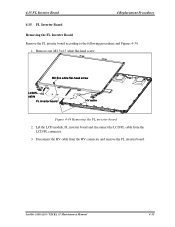
Remove one M2.5x4.5 white flat-head screw. Disconnect the HV cable from the LCD/FL connector. 3. Figure 4-34 Removing the FL inverter board 2. Lift the LCD module, FL inverter board and disconnect the LCD/FL cable from the HV connector and remove the FL inverter board. Satellite A100/A105 / TECRA A7 Maintenance Manual 4-55 4.15 FL Inverter Board 4 Replacement Procedures 4.15 FL Inverter Board Removing the FL Inverter Board Remove the FL inverter board according to the following procedures and Figures 4-34. 1.
Remove one M2.5x4.5 white flat-head screw. Disconnect the HV cable from the LCD/FL connector. 3. Figure 4-34 Removing the FL inverter board 2. Lift the LCD module, FL inverter board and disconnect the LCD/FL cable from the HV connector and remove the FL inverter board. Satellite A100/A105 / TECRA A7 Maintenance Manual 4-55 4.15 FL Inverter Board 4 Replacement Procedures 4.15 FL Inverter Board Removing the FL Inverter Board Remove the FL inverter board according to the following procedures and Figures 4-34. 1.
Maintenance Manual
Page 209
4 Replacement Procedures 4.15 FL Inverter Board Installing the FL Inverter Board Install the FL inverter board according to the HV connector. 2. Seat the LCD module, FL inverter board in the correct position. 3. Secure the FL inverter board with one M2.5x4.5 white flat-head screw. 4-56 Satellite A100/A105 / TECRA A7 Maintenance Manual Connect the LCD/FL cable to LCD/FL connector, and connect the HV cable to the following procedures and Figures 4-34. 1.
4 Replacement Procedures 4.15 FL Inverter Board Installing the FL Inverter Board Install the FL inverter board according to the HV connector. 2. Seat the LCD module, FL inverter board in the correct position. 3. Secure the FL inverter board with one M2.5x4.5 white flat-head screw. 4-56 Satellite A100/A105 / TECRA A7 Maintenance Manual Connect the LCD/FL cable to LCD/FL connector, and connect the HV cable to the following procedures and Figures 4-34. 1.

Maintenance Manual
Page 210
... (FL) tubes) as required by local ordinances or regulations. Remove two M2x3 white flat-head screws on each side securing the LCD bracket. Figure 4-35 Removing the 15.4-inch LCD module and screws Satellite A100/A105 / TECRA A7 Maintenance Manual 4-57 4.16 LCD Module 4 Replacement Procedures 4.16 LCD Modules NOTE: ICs are fragile. NOTE: Dispose of the...
... (FL) tubes) as required by local ordinances or regulations. Remove two M2x3 white flat-head screws on each side securing the LCD bracket. Figure 4-35 Removing the 15.4-inch LCD module and screws Satellite A100/A105 / TECRA A7 Maintenance Manual 4-57 4.16 LCD Module 4 Replacement Procedures 4.16 LCD Modules NOTE: ICs are fragile. NOTE: Dispose of the...

Maintenance Manual
Page 211
Figure 4-36 Removing the 15.4-inch LCD module 4-58 Satellite A100/A105 / TECRA A7 Maintenance Manual Be sure to place it on a cushioned surface such as a foam pad. 5. Turn the LCD upside down. Then disconnect the LCD/FL cable. 4 Replacement Procedures 4.16 LCD Module 3. Remove the tape and LCD/FL cable connector. Remove the LCD brackets. 4.
Figure 4-36 Removing the 15.4-inch LCD module 4-58 Satellite A100/A105 / TECRA A7 Maintenance Manual Be sure to place it on a cushioned surface such as a foam pad. 5. Turn the LCD upside down. Then disconnect the LCD/FL cable. 4 Replacement Procedures 4.16 LCD Module 3. Remove the tape and LCD/FL cable connector. Remove the LCD brackets. 4.

Maintenance Manual
Page 212
Turn the LCD upside down. 2. Connect the LCD/FL cable to the following procedures and Figures 4-35, 4-36. 1. Return the normal LCD placement. 4. Satellite A100/A105 / TECRA A7 Maintenance Manual 4-59 Install the 15.4-inch LCD module according to the LCD module connector. 3. Place the LCD bracket in the correct position and secure it from the module. 4.16 LCD Module 4 Replacement Procedures Installing the 15.4-inch LCD Module NOTE: LCD/FL cable must be carefully peeled away before disconnecting it with two M2x3 white flat-head screws on each side.
Turn the LCD upside down. 2. Connect the LCD/FL cable to the following procedures and Figures 4-35, 4-36. 1. Return the normal LCD placement. 4. Satellite A100/A105 / TECRA A7 Maintenance Manual 4-59 Install the 15.4-inch LCD module according to the LCD module connector. 3. Place the LCD bracket in the correct position and secure it from the module. 4.16 LCD Module 4 Replacement Procedures Installing the 15.4-inch LCD Module NOTE: LCD/FL cable must be carefully peeled away before disconnecting it with two M2x3 white flat-head screws on each side.


