Toshiba Online Users Guide for Satellite A100/A105
Page 107
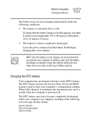
... power until it maintains this extends battery life and helps ensure accurate monitoring of battery capacity. The RTC battery powers the System Time Clock and BIOS memory used to a month when the computer is almost completely discharged. Charging the RTC battery Your computer has an internal real-time clock (RTC) battery...
... power until it maintains this extends battery life and helps ensure accurate monitoring of battery capacity. The RTC battery powers the System Time Clock and BIOS memory used to a month when the computer is almost completely discharged. Charging the RTC battery Your computer has an internal real-time clock (RTC) battery...
Toshiba Online Users Guide for Satellite A100/A105
Page 160
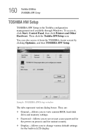
To access it from the TOSHIBA Assist screen by clicking Optimize, and then TOSHIBA HW Setup. Sample TOSHIBA HWSetup window The tabs represent various dialog boxes. They are: ❖ General-Allows you to view current BIOS, hard disk drive and memory settings. ❖ Password-Allows you to set or reset a user ... the built-in LCD display. You can also access it , click Start, Control Panel, then click Printers and Other Hardware. 160 Toshiba Utilities TOSHIBA HW Setup TOSHIBA HW Setup TOSHIBA HW Setup is the Toshiba configuration management tool available through Windows. Then click the...
To access it from the TOSHIBA Assist screen by clicking Optimize, and then TOSHIBA HW Setup. Sample TOSHIBA HWSetup window The tabs represent various dialog boxes. They are: ❖ General-Allows you to view current BIOS, hard disk drive and memory settings. ❖ Password-Allows you to set or reset a user ... the built-in LCD display. You can also access it , click Start, Control Panel, then click Printers and Other Hardware. 160 Toshiba Utilities TOSHIBA HW Setup TOSHIBA HW Setup TOSHIBA HW Setup is the Toshiba configuration management tool available through Windows. Then click the...
Toshiba Online Users Guide for Satellite A100/A105
Page 180
Interrupt Request Channel The channel to the CPU is a computer standard that helps the system BIOS (basic input/output system) and the operating system to automatically assign system resources to bypass the microprocessor and access memory directly. The DMA provides a dedicated ...
Interrupt Request Channel The channel to the CPU is a computer standard that helps the system BIOS (basic input/output system) and the operating system to automatically assign system resources to bypass the microprocessor and access memory directly. The DMA provides a dedicated ...
Toshiba Online Users Guide for Satellite A100/A105
Page 251
Glossary TECHNICAL NOTE: Some features defined in this glossary may not be available on your computer. Acronyms These acronyms may appear in this user's guide. AC alternating current BIOS basic input/output system bps bits per second CD compact disc CD-ROM compact disc read-only memory CD-RW compact disc rewrite memory CMOS complementary metal-oxide semiconductor COM1 communications port 1 (serial port) COM2 communications port 2 (serial port) CPU central processing unit 251
Glossary TECHNICAL NOTE: Some features defined in this glossary may not be available on your computer. Acronyms These acronyms may appear in this user's guide. AC alternating current BIOS basic input/output system bps bits per second CD compact disc CD-ROM compact disc read-only memory CD-RW compact disc rewrite memory CMOS complementary metal-oxide semiconductor COM1 communications port 1 (serial port) COM2 communications port 2 (serial port) CPU central processing unit 251
Toshiba Online Users Guide for Satellite A100/A105
Page 254
...is passed between two devices. Applications include word processors, spreadsheets, and database management systems. See also program. basic input/output system (BIOS) - Basic instructions, stored in readonly memory (ROM), containing the information the computer needs in case the original file is a ...program that loads and initializes the operating system. bits per second. Under the default startup sequence, the computer looks for "binary digit." BIOS (basic input/output system) - A group of a specific type. bus - The speed at which a communication device, such as...
...is passed between two devices. Applications include word processors, spreadsheets, and database management systems. See also program. basic input/output system (BIOS) - Basic instructions, stored in readonly memory (ROM), containing the information the computer needs in case the original file is a ...program that loads and initializes the operating system. bits per second. Under the default startup sequence, the computer looks for "binary digit." BIOS (basic input/output system) - A group of a specific type. bus - The speed at which a communication device, such as...
Toshiba Online Users Guide for Satellite A100/A105
Page 263
...used on a screen. See central processing unit (CPU). Compare ROM. See also boot. This type of pixels available horizontally and vertically. See also BIOS, memory. The attributes of a file include the file's type, size, and creation date. R RAM (random access memory) - Non-volatile memory .... By volatile, we mean that information in RAM is used to as well as the number of memory is used for your computer's BIOS, which is receiving power. resolution - For a screen, it up. This type of programs (also called software) are operating system, ...
...used on a screen. See central processing unit (CPU). Compare ROM. See also boot. This type of pixels available horizontally and vertically. See also BIOS, memory. The attributes of a file include the file's type, size, and creation date. R RAM (random access memory) - Non-volatile memory .... By volatile, we mean that information in RAM is used to as well as the number of memory is used for your computer's BIOS, which is receiving power. resolution - For a screen, it up. This type of programs (also called software) are operating system, ...
Toshiba Online Users Guide for Satellite A100/A105
Page 266
... charge 111 monitoring power 48, 108 not charging 184 power usage hot key 114 power usage mode 220 real-time clock (RTC) 105 removing 115 BIOS setup see Toshiba Hardware Setup button power 51 start 125 C CD creating 99 playing an audio 98 266
... charge 111 monitoring power 48, 108 not charging 184 power usage hot key 114 power usage mode 220 real-time clock (RTC) 105 removing 115 BIOS setup see Toshiba Hardware Setup button power 51 start 125 C CD creating 99 playing an audio 98 266

Maintenance Manual
Page 5
...resolve FRU problems. Chapter 3 Test and Diagnostics describes how to perform test and diagnostic operations for maintenance service. Board layout ? Wiring diagrams ? BIOS Rewrite Procedures Satellite A100/A105 / TECRA A7 Maintenance Manual v The manual is divided into the following : ? Handling the LCD module ? Chapter 4 Replacement Procedures describes the...the FRUs. Keyboard scan/character codes ? Key layout ? Appendices The appendices describe the following parts: Chapter 1 Hardware Overview describes the Satellite A100/A105 / TECRA A7 system unit and each FRU.
...resolve FRU problems. Chapter 3 Test and Diagnostics describes how to perform test and diagnostic operations for maintenance service. Board layout ? Wiring diagrams ? BIOS Rewrite Procedures Satellite A100/A105 / TECRA A7 Maintenance Manual v The manual is divided into the following : ? Handling the LCD module ? Chapter 4 Replacement Procedures describes the...the FRUs. Keyboard scan/character codes ? Key layout ? Appendices The appendices describe the following parts: Chapter 1 Hardware Overview describes the Satellite A100/A105 / TECRA A7 system unit and each FRU.

Maintenance Manual
Page 14
Appendices Appendix A Appendix B Appendix C Appendix D Appendix E Appendix F Appendix G Appendix H Handling the LCD Module A-1 Board Layout B-1 Keyboard Scan/Character Codes C-1 Key Layout...D-1 Wiring Diagrams E-1 BIOS Rewrite Procedures F-1 EC/KBC Rewrite Procedures G-1 GREASE NFORMATION H-1 xiv Satellite A100/A105 / TECRA A7 Maintenance Manual
Appendices Appendix A Appendix B Appendix C Appendix D Appendix E Appendix F Appendix G Appendix H Handling the LCD Module A-1 Board Layout B-1 Keyboard Scan/Character Codes C-1 Key Layout...D-1 Wiring Diagrams E-1 BIOS Rewrite Procedures F-1 EC/KBC Rewrite Procedures G-1 GREASE NFORMATION H-1 xiv Satellite A100/A105 / TECRA A7 Maintenance Manual
Maintenance Manual
Page 25
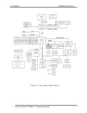
... SLOT A CO NN CO N N S ys t e m C h ar ge r & DC/DC S y st em po w er (IMVP -6 VR ) R J 11 MIC J AC K HP J AC K S P EA KER SMS C KBC 1100 BIO S FLAS H RO M 3-AXISSENSOR TP M 1. 2 S MS C S IO 1036 SERIALPORT F IR P ARA LLEL P O R T C IR Figure 1- 2 The computer Block diagram Satellite A100/A105 / TECRA A7 Maintenance Manual 7
... SLOT A CO NN CO N N S ys t e m C h ar ge r & DC/DC S y st em po w er (IMVP -6 VR ) R J 11 MIC J AC K HP J AC K S P EA KER SMS C KBC 1100 BIO S FLAS H RO M 3-AXISSENSOR TP M 1. 2 S MS C S IO 1036 SERIALPORT F IR P ARA LLEL P O R T C IR Figure 1- 2 The computer Block diagram Satellite A100/A105 / TECRA A7 Maintenance Manual 7
Maintenance Manual
Page 52
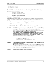
... check if the system board is faulty. If you press the F1 key as instructed. The error message appears when either data stored in the BIOS ROM. Satellite A100/A105 / TECRA A7 Maintenance Manual 2-9
... check if the system board is faulty. If you press the F1 key as instructed. The error message appears when either data stored in the BIOS ROM. Satellite A100/A105 / TECRA A7 Maintenance Manual 2-9
Maintenance Manual
Page 109
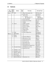
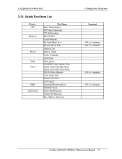
... 02 Interval Timer 03 Clock / Calendar 04 PCI System 05 Plug and Play 06 ACPI Test 03 FAN 01 CPU Fan Speed Test Memory 01 BIOS ROM 02 Parity 03 Pattern 01 Bit Stuck High Test 02 Bit Stuck Low Test 03 Checker Board Test 04 CAS Line Test 05 Incremental...] [MMX] [DMACtrl] [Timer] [RealClock] [PCI] [PnP] [ACPI] [FANSpeed] [BIOSROM] [Parity] [BSHigh] [BSLow] [ChkBd] [CASLine] [Incrment] [Decrment] [Idcrment] [XWRCycle ] [XRCycle ] [WalkHigh] [WalkLow] [Address] [Refresh] [CacheOne] [Random] Satellite A100/A105 / TECRA A7 Maintenance Manual 33
... 02 Interval Timer 03 Clock / Calendar 04 PCI System 05 Plug and Play 06 ACPI Test 03 FAN 01 CPU Fan Speed Test Memory 01 BIOS ROM 02 Parity 03 Pattern 01 Bit Stuck High Test 02 Bit Stuck Low Test 03 Checker Board Test 04 CAS Line Test 05 Incremental...] [MMX] [DMACtrl] [Timer] [RealClock] [PCI] [PnP] [ACPI] [FANSpeed] [BIOSROM] [Parity] [BSHigh] [BSLow] [ChkBd] [CASLine] [Incrment] [Decrment] [Idcrment] [XWRCycle ] [XRCycle ] [WalkHigh] [WalkLow] [Address] [Refresh] [CacheOne] [Random] Satellite A100/A105 / TECRA A7 Maintenance Manual 33

Maintenance Manual
Page 114
PCI System This test item is an ESCD (Extended System Configuration Data) in the BIOS; 3. Whether there is to check whether the bus number, device number and function number in the system; 4. items as below: System Address Map Test: Check... 5. Subtest 03 FAN Speed Test 1. Whether there is within real memory. ACPI Table Test: Check the correctness of stop, slow, middle and fast. 38 Satellite A100/A105 / TECRA A7 Maintenance Manual 3 Diagnostic Programs 3.5 System Test This test item is to check whether the system clock/calendar works normally. 4. Clock/Calendar This test...
PCI System This test item is an ESCD (Extended System Configuration Data) in the BIOS; 3. Whether there is to check whether the bus number, device number and function number in the system; 4. items as below: System Address Map Test: Check... 5. Subtest 03 FAN Speed Test 1. Whether there is within real memory. ACPI Table Test: Check the correctness of stop, slow, middle and fast. 38 Satellite A100/A105 / TECRA A7 Maintenance Manual 3 Diagnostic Programs 3.5 System Test This test item is to check whether the system clock/calendar works normally. 4. Clock/Calendar This test...
Maintenance Manual
Page 116
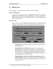
... could be tested. If user chooses Total Size, it means that includes two sub- Subtest 02 Parity This test item is to check whether BIOS ROM is write-protected. Base Memory or Extended Memory. items -ROM Read and ROM Write Protection. 3 Diagnostic Programs 3.6 Memory Test 3.6 Memory... the whole Extended Momory will be based on the setting and the value in 'Percent (%) mentioned at below. 40 Satellite A100/A105 / TECRA A7 Maintenance Manual Subtest 01 BIOS ROM This test item is to check the validity of Extended Momory. Below is invalid. Test Option: Choose the Memory...
... could be tested. If user chooses Total Size, it means that includes two sub- Subtest 02 Parity This test item is to check whether BIOS ROM is write-protected. Base Memory or Extended Memory. items -ROM Read and ROM Write Protection. 3 Diagnostic Programs 3.6 Memory Test 3.6 Memory... the whole Extended Momory will be based on the setting and the value in 'Percent (%) mentioned at below. 40 Satellite A100/A105 / TECRA A7 Maintenance Manual Subtest 01 BIOS ROM This test item is to check the validity of Extended Momory. Below is invalid. Test Option: Choose the Memory...

Maintenance Manual
Page 139
...the one that has been written in all device are set expected value. Replace the CPU. 02xx Memory 01 Read Error The ROM BIOS has Physical Test this address. As above . 08 CPU Information Error Information of the CPU cannot Check whether the CPU is damaged..... Action Check whether the interactive test mode is adopted. 01xx CPU 01 CPU General Function Error The CPU General Function register is damaged. Satellite A100/A105 / TECRA A7 Maintenance Manual 63 Check whether the CPU is the error code of device (2 chars); 3.11Error Codes and Description 3 Diagnostic...
...the one that has been written in all device are set expected value. Replace the CPU. 02xx Memory 01 Read Error The ROM BIOS has Physical Test this address. As above . 08 CPU Information Error Information of the CPU cannot Check whether the CPU is damaged..... Action Check whether the interactive test mode is adopted. 01xx CPU 01 CPU General Function Error The CPU General Function register is damaged. Satellite A100/A105 / TECRA A7 Maintenance Manual 63 Check whether the CPU is the error code of device (2 chars); 3.11Error Codes and Description 3 Diagnostic...
Maintenance Manual
Page 142
..., and repeat 04 FIFO Test Error LPT cannot perform normally under FIF0 TEST mode (ECP internal mode). Check the external fixture and BIOS setup, and repeat the test. 06 No Fixture On The Port No external fixtures on LPT port. card has any physical problem. ...05 IRQ Active Error 1.LPT IRQ cannot be activated. 2. BIOS setup, and repeat the test. 02 Control Register Error The control register can not perform Check the external fixture and normally. As above . Lower LCD color resolution. As above . 66 Satellite A100/A105 / TECRA A7 Maintenance Manual As above . 31xx Audio ...
..., and repeat 04 FIFO Test Error LPT cannot perform normally under FIF0 TEST mode (ECP internal mode). Check the external fixture and BIOS setup, and repeat the test. 06 No Fixture On The Port No external fixtures on LPT port. card has any physical problem. ...05 IRQ Active Error 1.LPT IRQ cannot be activated. 2. BIOS setup, and repeat the test. 02 Control Register Error The control register can not perform Check the external fixture and normally. As above . Lower LCD color resolution. As above . 66 Satellite A100/A105 / TECRA A7 Maintenance Manual As above . 31xx Audio ...

Maintenance Manual
Page 143
As above. 11 Toshiba Fixture Error As above . As above . As above. 05 57600BPS Test Error As above . As above . Check executed. LAN Card 01 PCI bus Error during device ID test Don't Scan PCI device Don't support PCI BIOS PCI Ethernet card not 02 present during MAC test Don't... find Net card test Please insert Net cad 03 Intel PCI Ethernet card not present during device ID Don't find IEEE1394 Don't support 1394. Satellite A100/A105 / TECRA A7 Maintenance Manual 67 As above. 03 19200BPS Test Error As above . As above. 04 38400BPS Test Error As above . There...
As above. 11 Toshiba Fixture Error As above . As above . As above. 05 57600BPS Test Error As above . As above . Check executed. LAN Card 01 PCI bus Error during device ID test Don't Scan PCI device Don't support PCI BIOS PCI Ethernet card not 02 present during MAC test Don't... find Net card test Please insert Net cad 03 Intel PCI Ethernet card not present during device ID Don't find IEEE1394 Don't support 1394. Satellite A100/A105 / TECRA A7 Maintenance Manual 67 As above. 03 19200BPS Test Error As above . As above. 04 38400BPS Test Error As above . There...
Maintenance Manual
Page 145
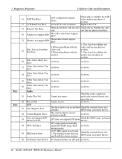
... Item List 3.12 Quick Test Item List Device CPU Memory Board FAN Video HDD LAN Card Test Items Basic Functionality NPU Basic Functions CPU Information BIOS ROM Cache Memory Bit Stuck High Test Bit Stuck Low Test Address Test Interval Timer Clock / Calendar ACPI Test FAN Speed 1024X768 Video Modes Test... Check Device ID Detection Vendor ID Detection Mac Address Detection 3 Diagnostic Programs Comment 10% or 3 minutes 10% or 3 minutes 10% or 3 minutes 25% or 3 minutes Satellite A100/A105 / TECRA A7 Maintenance Manual 67
... Item List 3.12 Quick Test Item List Device CPU Memory Board FAN Video HDD LAN Card Test Items Basic Functionality NPU Basic Functions CPU Information BIOS ROM Cache Memory Bit Stuck High Test Bit Stuck Low Test Address Test Interval Timer Clock / Calendar ACPI Test FAN Speed 1024X768 Video Modes Test... Check Device ID Detection Vendor ID Detection Mac Address Detection 3 Diagnostic Programs Comment 10% or 3 minutes 10% or 3 minutes 10% or 3 minutes 25% or 3 minutes Satellite A100/A105 / TECRA A7 Maintenance Manual 67
Maintenance Manual
Page 291
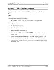
...the external cable and PC card. 4. Rewriting the BIOS 1. Apx. BIOS/EC/KBC rewriting disk for the computer that has renewed BIOS data. Satellite A100/A105 / TECRA A7 Maintenance Manual F-1 When the process is completed, eject the BIOS/EC/KBC rewriting disk and the system is automatically ...reset. Turn off the power to rewrite the system BIOS program when you need the ...
...the external cable and PC card. 4. Rewriting the BIOS 1. Apx. BIOS/EC/KBC rewriting disk for the computer that has renewed BIOS data. Satellite A100/A105 / TECRA A7 Maintenance Manual F-1 When the process is completed, eject the BIOS/EC/KBC rewriting disk and the system is automatically ...reset. Turn off the power to rewrite the system BIOS program when you need the ...
Maintenance Manual
Page 292
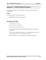
... Procedures This Appendix explains how to rewrite the EC/KBC system program when you need the following tool: ? Connect an external FDD and insert the BIOS/EC/KBC rewriting disk into either the external FDD. 5. Turn on the power while holding down the [`~] key. (Keep holding down the key until ...a message appears on the screen.) The EC/KBC rewriting starts. 6. BIOS/EC/KBC rewriting disk for the computer Rewriting the EC/KBC 1. Set the system to the computer. 3. When the EC/KBC rewrite is completed, the...
... Procedures This Appendix explains how to rewrite the EC/KBC system program when you need the following tool: ? Connect an external FDD and insert the BIOS/EC/KBC rewriting disk into either the external FDD. 5. Turn on the power while holding down the [`~] key. (Keep holding down the key until ...a message appears on the screen.) The EC/KBC rewriting starts. 6. BIOS/EC/KBC rewriting disk for the computer Rewriting the EC/KBC 1. Set the system to the computer. 3. When the EC/KBC rewrite is completed, the...


