
Service Manual
Page 2
... 4 PICTURE TUBE COMPONENTS ADJUSTMENT ...6 REPLACEMENT OF THE CRT ...8 SERVICE MODE ...9 ELECTRICAL ADJUSTMENT ...11 CONVERGENCE ADJUSTMENT ...13 SCREEN AND MIRROR ALIGNMENTS ...15 CIRCUIT CHECKS ...16 CHAPTER 2 SPECIFIC INFORMATIONS SETTING & ADJUSTING DATA ...17 LOCATION OF CONTROLS ...18 PROGRAMMING CHANNEL MEMORY ...20 CIRCUIT BLOCK DIAGRAM ...21 MECHANICAL DISASSEMBLY ...23 CHASSIS REPLACEMENT PARTS LIST ...25...
... 4 PICTURE TUBE COMPONENTS ADJUSTMENT ...6 REPLACEMENT OF THE CRT ...8 SERVICE MODE ...9 ELECTRICAL ADJUSTMENT ...11 CONVERGENCE ADJUSTMENT ...13 SCREEN AND MIRROR ALIGNMENTS ...15 CIRCUIT CHECKS ...16 CHAPTER 2 SPECIFIC INFORMATIONS SETTING & ADJUSTING DATA ...17 LOCATION OF CONTROLS ...18 PROGRAMMING CHANNEL MEMORY ...20 CIRCUIT BLOCK DIAGRAM ...21 MECHANICAL DISASSEMBLY ...23 CHASSIS REPLACEMENT PARTS LIST ...25...

Service Manual
Page 3
... RADIATION. The nominal value of the high voltage of the service record. AC VOLTMETER Good earth ground such as a part of this receiver. GENERAL ADJUSTMENTS SPECIFIC INFORMATIONS CHAPTER 1 GENERAL ADJUSTMENTS SAFETY INSTRUCTIONS WARNING: BEFORE SERVICING THIS CHASSIS, READ THE "X-RAY RADIATION PRECAUTION", "SAFETY PRECAUTION" AND "PRODUCT SAFETY NOTICE" INSTRUCTIONS BELOW. It...
... RADIATION. The nominal value of the high voltage of the service record. AC VOLTMETER Good earth ground such as a part of this receiver. GENERAL ADJUSTMENTS SPECIFIC INFORMATIONS CHAPTER 1 GENERAL ADJUSTMENTS SAFETY INSTRUCTIONS WARNING: BEFORE SERVICING THIS CHASSIS, READ THE "X-RAY RADIATION PRECAUTION", "SAFETY PRECAUTION" AND "PRODUCT SAFETY NOTICE" INSTRUCTIONS BELOW. It...

Service Manual
Page 4
R G B 8 o'clock 4 o'clock Attention Serviceman The Hex Head Bolts with Springs. (see sketch) used on CRT assembly, are "NOT" Adjustment Screws DO NOT LOOSEN-FLUID LEAKAGE WILL OCCUR. 4 Screws Lens Assembly CRT Assembly CRT Anode Cap Assembly S.V.M. GENERAL ADJUSTMENTS SPECIFIC INFORMATIONS CRT ASSEMBLY REPLACEMENT AND MOUNTING CAUTION : DO NOT LOOSEN THE HEX HEAD BOLTS WITH SPRINGS (12 PCS), BECAUSE THOSE ARE FOR SEALING OF CRT COOLANT. Coil 4 Screws CRT DRIVE Board CRT Mounting Deflection Yoke and Conver Yoke Lens and Neck Components View - 4 -
R G B 8 o'clock 4 o'clock Attention Serviceman The Hex Head Bolts with Springs. (see sketch) used on CRT assembly, are "NOT" Adjustment Screws DO NOT LOOSEN-FLUID LEAKAGE WILL OCCUR. 4 Screws Lens Assembly CRT Assembly CRT Anode Cap Assembly S.V.M. GENERAL ADJUSTMENTS SPECIFIC INFORMATIONS CRT ASSEMBLY REPLACEMENT AND MOUNTING CAUTION : DO NOT LOOSEN THE HEX HEAD BOLTS WITH SPRINGS (12 PCS), BECAUSE THOSE ARE FOR SEALING OF CRT COOLANT. Coil 4 Screws CRT DRIVE Board CRT Mounting Deflection Yoke and Conver Yoke Lens and Neck Components View - 4 -

Service Manual
Page 5
... on page 4. R.G.B. CENTERING ADJUSTMENT (page 6.) 5. WHITE BALANCE ADJUSTMENT (page 12.) Adjustments are complete. Anode Cap Silicon (On shaded area) TSE3843W #23960136 15 ~ 25 mm 2 ~ 5 mm SPECIFIC INFORMATIONS SERVICING PRECAUTIONS s Do not use a magnetized screw driver for R, G, B) 1. YOKE from CRT. 4. ADJUSTING PROCEDURE IN REPLACING CRT 1. Magnetization of electron gun will degrade basic...
... on page 4. R.G.B. CENTERING ADJUSTMENT (page 6.) 5. WHITE BALANCE ADJUSTMENT (page 12.) Adjustments are complete. Anode Cap Silicon (On shaded area) TSE3843W #23960136 15 ~ 25 mm 2 ~ 5 mm SPECIFIC INFORMATIONS SERVICING PRECAUTIONS s Do not use a magnetized screw driver for R, G, B) 1. YOKE from CRT. 4. ADJUSTING PROCEDURE IN REPLACING CRT 1. Magnetization of electron gun will degrade basic...

Service Manual
Page 6
.... 4. PICTURE TUBE COMPONENTS ADJUSTMENT DESCRIPTION OF NECK COMPONENTS ᕄ ᕃ TILT ADJUSTMENT Rotate R, G, B deflection yoke so that picture becomes horizon, then fasten screw. GENERAL ADJUSTMENTS SPECIFIC INFORMATIONS WARNING : BEFORE SERVICING THIS CHASSIS, READ THE "X-RAY RADIATION PRECAUTION", "SAFETY PRECAUTION" AND "PRODUCT SAFETY NOTICE" ON PAGE 3 OF THIS MANUAL. In order to...
.... 4. PICTURE TUBE COMPONENTS ADJUSTMENT DESCRIPTION OF NECK COMPONENTS ᕄ ᕃ TILT ADJUSTMENT Rotate R, G, B deflection yoke so that picture becomes horizon, then fasten screw. GENERAL ADJUSTMENTS SPECIFIC INFORMATIONS WARNING : BEFORE SERVICING THIS CHASSIS, READ THE "X-RAY RADIATION PRECAUTION", "SAFETY PRECAUTION" AND "PRODUCT SAFETY NOTICE" ON PAGE 3 OF THIS MANUAL. In order to...

Service Manual
Page 7
GENERAL ADJUSTMENTS SPECIFIC INFORMATIONS LOCATION OF SCREEN AND FOCUS VR'S SCREEN VR FOCUS VR RGB - 7 -
GENERAL ADJUSTMENTS SPECIFIC INFORMATIONS LOCATION OF SCREEN AND FOCUS VR'S SCREEN VR FOCUS VR RGB - 7 -

Service Manual
Page 8
HITACHI CRT 50A50 50A60 55A60 61A60 R 23796001 23005114 23005242 23005249 G 23005397 23005115 ↑ ↑ B 23796003 ↑ ↑ 23796486 REPLACEMENT OF HIGH VOLTAGE CABLE ANODE LEAD RUBBER BOOT LEAD HOLDER 1. RUBBER BOOT .... b Cut here rubber boot and lead together to detach Lead Holder. - 8 - Detaching Lead Holder RUBBER BOOT OLD ANODE LEAD or ANODE CAP Fig. GENERAL ADJUSTMENTS SPECIFIC INFORMATIONS REPLACEMENT OF THE CRT Service parts are as shown in figure below, and put it on new lead. When replacing Anode Lead or Anode...
HITACHI CRT 50A50 50A60 55A60 61A60 R 23796001 23005114 23005242 23005249 G 23005397 23005115 ↑ ↑ B 23796003 ↑ ↑ 23796486 REPLACEMENT OF HIGH VOLTAGE CABLE ANODE LEAD RUBBER BOOT LEAD HOLDER 1. RUBBER BOOT .... b Cut here rubber boot and lead together to detach Lead Holder. - 8 - Detaching Lead Holder RUBBER BOOT OLD ANODE LEAD or ANODE CAP Fig. GENERAL ADJUSTMENTS SPECIFIC INFORMATIONS REPLACEMENT OF THE CRT Service parts are as shown in figure below, and put it on new lead. When replacing Anode Lead or Anode...

Service Manual
Page 9
... TV or Remote) Volume s/t (on TV or Remote) MENU button (on TV) RECALL+Channel button on TV (s) RECALL+Channel button on Remote Control. GENERAL ADJUSTMENTS SPECIFIC INFORMATIONS 1. DISPLAYING THE ADJUSTMENT MENU 1) Press MENU button on TV set. SERVICE MODE 2) Press MUTE button again to keep pressing. 3) While pressing the MUTE button...
... TV or Remote) Volume s/t (on TV or Remote) MENU button (on TV) RECALL+Channel button on TV (s) RECALL+Channel button on Remote Control. GENERAL ADJUSTMENTS SPECIFIC INFORMATIONS 1. DISPLAYING THE ADJUSTMENT MENU 1) Press MENU button on TV set. SERVICE MODE 2) Press MUTE button again to keep pressing. 3) While pressing the MUTE button...

Service Manual
Page 10
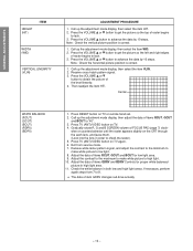
... TV once. SELF DIAGNOSTIC FUNCTION 1) Press "9" button on the owner's manual. When repair of a failure place finishes, the next failure place is required. 1. GENERAL ADJUSTMENTS SPECIFIC INFORMATIONS 4. SELECTING THE ADJUSTING ITEMS 1) Every pressing of CHANNEL s button in the service mode changes the adjustment items in the service mode. Perform "Programming Channel...
... TV once. SELF DIAGNOSTIC FUNCTION 1) Press "9" button on the owner's manual. When repair of a failure place finishes, the next failure place is required. 1. GENERAL ADJUSTMENTS SPECIFIC INFORMATIONS 4. SELECTING THE ADJUSTING ITEMS 1) Every pressing of CHANNEL s button in the service mode changes the adjustment items in the service mode. Perform "Programming Channel...

Service Manual
Page 11
... METER SUB-BRIGHTNESS (BRTC) SUB-COLOR (SCOL) SUB-TINT (TNTC) SUB-CONTRAST (SCNT) PICTURE POSITION 1. Receive color-bar signal from color-bar generator. 2. GENERAL ADJUSTMENTS SPECIFIC INFORMATIONS ELECTRICAL ADJUSTMENT ITEM VERTICAL POSITION (VCEN) ADJUSTMENT PROCEDURE 1. Call up the adjustment mode display, then select item VCEN. 2. Press the VOLUME s or t button to...
... METER SUB-BRIGHTNESS (BRTC) SUB-COLOR (SCOL) SUB-TINT (TNTC) SUB-CONTRAST (SCNT) PICTURE POSITION 1. Receive color-bar signal from color-bar generator. 2. GENERAL ADJUSTMENTS SPECIFIC INFORMATIONS ELECTRICAL ADJUSTMENT ITEM VERTICAL POSITION (VCEN) ADJUSTMENT PROCEDURE 1. Call up the adjustment mode display, then select item VCEN. 2. Press the VOLUME s or t button to...
Service Manual
Page 12
... the minimum to make white picture to low light. 8. Adjust the contrast to the maximum to make white picture to high light. 10. GENERAL ADJUSTMENTS SPECIFIC INFORMATIONS HEIGHT (HIT) ITEM WIDTH (WID) VERTICAL LINEARITY (VLIN) ADJUSTMENT PROCEDURE 1. Press the VOLUME s or t button to "40". 3. Call up the adjustment mode display, then...
... the minimum to make white picture to low light. 8. Adjust the contrast to the maximum to make white picture to high light. 10. GENERAL ADJUSTMENTS SPECIFIC INFORMATIONS HEIGHT (HIT) ITEM WIDTH (WID) VERTICAL LINEARITY (VLIN) ADJUSTMENT PROCEDURE 1. Press the VOLUME s or t button to "40". 3. Call up the adjustment mode display, then...

Service Manual
Page 13
.... 1. This means that the Red color is about 1 second. 11. HIT, WID ADJUSTMENT 5. Press "3" button to select Green color to erase Blue line 6. GENERAL ADJUSTMENTS SPECIFIC INFORMATIONS CONVERGENCE ADJUSTMENT Adjust convergence from the screen. 100 button to erase Red line 0 button to erase Green line RTN (ENT) button to be blinking...
.... 1. This means that the Red color is about 1 second. 11. HIT, WID ADJUSTMENT 5. Press "3" button to select Green color to erase Blue line 6. GENERAL ADJUSTMENTS SPECIFIC INFORMATIONS CONVERGENCE ADJUSTMENT Adjust convergence from the screen. 100 button to erase Red line 0 button to erase Green line RTN (ENT) button to be blinking...

Service Manual
Page 14
... When replacing convergence unit, all picture screens require readjustment basically, but the following procedures. 1. Following cases will surely require readjustment of main deflec- GENERAL ADJUSTMENTS SPECIFIC INFORMATIONS NOTES In many cases, color misconvergence may be reduced considerably. 1.
... When replacing convergence unit, all picture screens require readjustment basically, but the following procedures. 1. Following cases will surely require readjustment of main deflec- GENERAL ADJUSTMENTS SPECIFIC INFORMATIONS NOTES In many cases, color misconvergence may be reduced considerably. 1.

Service Manual
Page 15
... a dry cloth to remove moisture on page 23. GENERAL ADJUSTMENTS ASSEMBLING OF FRONT SCREEN SCREEN AND MIRROR ALIGNMENTS Fresnel sheet MOUNTING OF FRONT SCREEN 5 screws SPECIFIC INFORMATIONS FRONT Protect shield (for 50") Lenticular sheet Protect shield FRONT Fresnel sheet Label with part number Stick cotton cloth tape Label with part number...
... a dry cloth to remove moisture on page 23. GENERAL ADJUSTMENTS ASSEMBLING OF FRONT SCREEN SCREEN AND MIRROR ALIGNMENTS Fresnel sheet MOUNTING OF FRONT SCREEN 5 screws SPECIFIC INFORMATIONS FRONT Protect shield (for 50") Lenticular sheet Protect shield FRONT Fresnel sheet Label with part number Stick cotton cloth tape Label with part number...

Service Manual
Page 16
... wire. Troubleshooting Guide for the final check in this state even after replacing. YES (See SETTING & ADJUSTING DATA on the receiver. Location No. GENERAL ADJUSTMENTS SPECIFIC INFORMATIONS CIRCUIT CHECKS HIGH VOLTAGE CHECK CAUTION: There is no HIGH VOLTAGE ADJUSTMENT on this high voltage. T461 C447 C406 C407 Name Flyback Trans. The...
... wire. Troubleshooting Guide for the final check in this state even after replacing. YES (See SETTING & ADJUSTING DATA on the receiver. Location No. GENERAL ADJUSTMENTS SPECIFIC INFORMATIONS CIRCUIT CHECKS HIGH VOLTAGE CHECK CAUTION: There is no HIGH VOLTAGE ADJUSTMENT on this high voltage. T461 C447 C406 C407 Name Flyback Trans. The...
Service Manual
Page 17
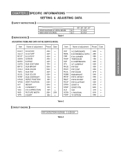
... VSC WID VPS R CUTOFF G CUTOFF B CUTOFF G DRIVE B DRIVE SUB CONT MAX SUB-BRIGHT SUB-COLOR SUB-TINT SUB COLOR SUB-CONTRAST HORIZ. GENERAL ADJUSTMENTS SPECIFIC INFORMATIONS CHAPTER 2 SPECIFIC INFORMATIONS SETTING & ADJUSTING DATA SAFETY INSTRUCTIONS SERVICE MODE 43", 50", 55", 61" HIGH VOLTAGE AT ZERO BEAM: (A) 31.3 kV MAX HIGH VOLTAGE: (B) 32.4 kV...
... VSC WID VPS R CUTOFF G CUTOFF B CUTOFF G DRIVE B DRIVE SUB CONT MAX SUB-BRIGHT SUB-COLOR SUB-TINT SUB COLOR SUB-CONTRAST HORIZ. GENERAL ADJUSTMENTS SPECIFIC INFORMATIONS CHAPTER 2 SPECIFIC INFORMATIONS SETTING & ADJUSTING DATA SAFETY INSTRUCTIONS SERVICE MODE 43", 50", 55", 61" HIGH VOLTAGE AT ZERO BEAM: (A) 31.3 kV MAX HIGH VOLTAGE: (B) 32.4 kV...

Service Manual
Page 19
CAPT ENTER FAV t RESET PIP CH t LIGHT RECALL POWER TV CABLE VCR MUTE TV/VIDEO TIMER 12 45 3 CH 6 7 100 C.CAPT 89 CH RTN VOL 0 ENT ADV/ PIP CH MENU FAV ENTER FAV RESET ADV/ EXIT PIP CH STOP SOURCE PLAY PIP REC TV/VCR REW FF STILL LOCATE SWAP RECALL POWER TIMER TV/VIDEO CHANNEL s/t VOLUME s/t CH RTN MENU PIP CH s FAV s s/t/T/S EXIT PIP functions (For "TV" and "CABLE" modes) - 19 - MUTE Channel Number C. GENERAL ADJUSTMENTS SPECIFIC INFORMATIONS Remote Control LIGHT TV/CABLE/VCR switch Set to "TV" to control the TV.
CAPT ENTER FAV t RESET PIP CH t LIGHT RECALL POWER TV CABLE VCR MUTE TV/VIDEO TIMER 12 45 3 CH 6 7 100 C.CAPT 89 CH RTN VOL 0 ENT ADV/ PIP CH MENU FAV ENTER FAV RESET ADV/ EXIT PIP CH STOP SOURCE PLAY PIP REC TV/VCR REW FF STILL LOCATE SWAP RECALL POWER TIMER TV/VIDEO CHANNEL s/t VOLUME s/t CH RTN MENU PIP CH s FAV s s/t/T/S EXIT PIP functions (For "TV" and "CABLE" modes) - 19 - MUTE Channel Number C. GENERAL ADJUSTMENTS SPECIFIC INFORMATIONS Remote Control LIGHT TV/CABLE/VCR switch Set to "TV" to control the TV.

Service Manual
Page 20
GENERAL ADJUSTMENTS SPECIFIC INFORMATIONS PROGRAMMING CHANNEL MEMORY The channel memory is the list of TV channel numbers the TV tunes in your area automatically. You have now completed .... 5 Repeat steps 1 to 4 for each input source. If necessary, arrange the preset channels with the ADD/ERASE functions so that you can add or erase specific channels. 1 Select the channel you want to start channel programming. To add the channel press the button until "TV/CABLE" is on the screen. * Please...
GENERAL ADJUSTMENTS SPECIFIC INFORMATIONS PROGRAMMING CHANNEL MEMORY The channel memory is the list of TV channel numbers the TV tunes in your area automatically. You have now completed .... 5 Repeat steps 1 to 4 for each input source. If necessary, arrange the preset channels with the ADD/ERASE functions so that you can add or erase specific channels. 1 Select the channel you want to start channel programming. To add the channel press the button until "TV/CABLE" is on the screen. * Please...

Service Manual
Page 23
...630V PF, 3.3?F, ±10%, 100V PF, 0.047?F, 200V CD, 220pF, ±10%, 500V PF, 0.47?F, 400V - 25 - Models : 50A60/50A50/55A60/61A60 Capacitors CD : Ceramic Disk PF : Plastic Film EL : Resistors CF : Carbon Film CC : Carbon Composition MF : OMF : Oxide Metal Film VR : Variable Resistor... C352 C401 C401 C402 C402 C403 C404 C404 C405 * C406 * C407 * C408 C410 C412 C413 * C414 Part No. GENERAL ADJUSTMENTS SPECIFIC INFORMATIONS CHASSIS REPLACEMENT PARTS LIST WARNING: BEFORE SERVICING THIS CHASSIS, READ THE "X-RAY RADIATION PRECAUTION", "SAFETY PRECAUTION" AND "PRODUCT SAFETY NOTICE"...
...630V PF, 3.3?F, ±10%, 100V PF, 0.047?F, 200V CD, 220pF, ±10%, 500V PF, 0.47?F, 400V - 25 - Models : 50A60/50A50/55A60/61A60 Capacitors CD : Ceramic Disk PF : Plastic Film EL : Resistors CF : Carbon Film CC : Carbon Composition MF : OMF : Oxide Metal Film VR : Variable Resistor... C352 C401 C401 C402 C402 C403 C404 C404 C405 * C406 * C407 * C408 C410 C412 C413 * C414 Part No. GENERAL ADJUSTMENTS SPECIFIC INFORMATIONS CHASSIS REPLACEMENT PARTS LIST WARNING: BEFORE SERVICING THIS CHASSIS, READ THE "X-RAY RADIATION PRECAUTION", "SAFETY PRECAUTION" AND "PRODUCT SAFETY NOTICE"...

Service Manual
Page 33
..., 330 ohm, 1/16W Chip, 330 ohm, 1/16W COILS & TRANSFORMERS L101 23289845 Coil, Peaking, TRF4680AT L111 23289845 Coil, Peaking, TRF4680AT (50A60/55A60/61A60) L115 23103852 Coil, Filter, TEM2028AH (50A60/55A60/61A60) L121 23238562 Coil, Peaking, TRF4109AJ L122 23238562 Coil, Peaking, TRF4109AJ L301 23237975 Coil, Peaking, TRF4101AC L302 23248073 Coil, Choke, TLN3299D L303 23248073... Bead), TEM2011 - 35 - RZ03 RZ04 RZ05 RZ06 RZ08 RZ09 RZ10 RZ12 RZ13 RZ14 RZ15 RZ17 RZ18 RZ19 RZ20 RZ22 RZ29 RZ30 Part No. GENERAL ADJUSTMENTS SPECIFIC INFORMATIONS Location No.
..., 330 ohm, 1/16W Chip, 330 ohm, 1/16W COILS & TRANSFORMERS L101 23289845 Coil, Peaking, TRF4680AT L111 23289845 Coil, Peaking, TRF4680AT (50A60/55A60/61A60) L115 23103852 Coil, Filter, TEM2028AH (50A60/55A60/61A60) L121 23238562 Coil, Peaking, TRF4109AJ L122 23238562 Coil, Peaking, TRF4109AJ L301 23237975 Coil, Peaking, TRF4101AC L302 23248073 Coil, Choke, TLN3299D L303 23248073... Bead), TEM2011 - 35 - RZ03 RZ04 RZ05 RZ06 RZ08 RZ09 RZ10 RZ12 RZ13 RZ14 RZ15 RZ17 RZ18 RZ19 RZ20 RZ22 RZ29 RZ30 Part No. GENERAL ADJUSTMENTS SPECIFIC INFORMATIONS Location No.