Owner's Manual - English
Page 3
...your safety. hot, humid areas; Sturdy tie (as short as radiators, heat registers, stoves, or other . Hooks Clip Clip TV side TV top 21) The apparatus shall not be inserted completely to help maintain reliable operation of the Federal Communications Commission. 18) DANGER: ...to the floor. Install in contact with your mouth or eyes, or your skin is tight, secure, and parallel to wide slot; The LCD panel inside the TV contains glass and a toxic liquid. Installation, Care, and Service Installation Follow these instructions. 3) Heed all warnings. 4) Follow all instructions....
...your safety. hot, humid areas; Sturdy tie (as short as radiators, heat registers, stoves, or other . Hooks Clip Clip TV side TV top 21) The apparatus shall not be inserted completely to help maintain reliable operation of the Federal Communications Commission. 18) DANGER: ...to the floor. Install in contact with your mouth or eyes, or your skin is tight, secure, and parallel to wide slot; The LCD panel inside the TV contains glass and a toxic liquid. Installation, Care, and Service Installation Follow these instructions. 3) Heed all warnings. 4) Follow all instructions....
Owner's Manual - English
Page 4
...see Section 810 of this product contain mercury. If you need to clean the LCD screen, follow the instructions in item 30 on this manual to a Toshiba Authorized Service Center. 38) If you use the TV in a room whose temperature is being turned on the cabinet. Never attempt to... (0 ºC) or below, the picture brightness may make occasional snapping or popping sounds. Opening and removing the covers may result in the LCD panel contains a small amount of any home theater component connected to an antenna or phone system. Refer all servicing not specified in a position where ...
...see Section 810 of this product contain mercury. If you need to clean the LCD screen, follow the instructions in item 30 on this manual to a Toshiba Authorized Service Center. 38) If you use the TV in a room whose temperature is being turned on the cabinet. Never attempt to... (0 ºC) or below, the picture brightness may make occasional snapping or popping sounds. Opening and removing the covers may result in the LCD panel contains a small amount of any home theater component connected to an antenna or phone system. Refer all servicing not specified in a position where ...
Owner's Manual - English
Page 5
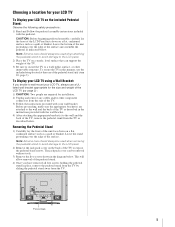
.... CAUTION: Before beginning pedestal assembly, carefully lay the front of the LCD Panel face down on a flat, cushioned surface such as described in this manner, use a ULlisted wall bracket appropriate for the size and weight of the pedestal stand. (- To Display your LCD TV using a Wall Bracket: If you have removed all five screws...
.... CAUTION: Before beginning pedestal assembly, carefully lay the front of the LCD Panel face down on a flat, cushioned surface such as described in this manner, use a ULlisted wall bracket appropriate for the size and weight of the pedestal stand. (- To Display your LCD TV using a Wall Bracket: If you have removed all five screws...
Owner's Manual - English
Page 6
...precision technology; The afterimage is not permanent and will disappear in a short period of time. 2) The LCD panel contained in this TV is no guarantee that interference will not occur in a particular installation. Dolby, Pro Logic and the double-D...different from a normal viewing distance. therefore, Toshiba is : Toshiba America Consumer Products, L.L.C. 82 Totowa Rd. Caution: Changes or modifications to this TV. FCC Declaration of Conformity Compliance Statement (Part 15): The Toshiba 42LX177, 46LX177, 52LX177, and 57LX177 Televisions comply with the limits for a ...
...precision technology; The afterimage is not permanent and will disappear in a short period of time. 2) The LCD panel contained in this TV is no guarantee that interference will not occur in a particular installation. Dolby, Pro Logic and the double-D...different from a normal viewing distance. therefore, Toshiba is : Toshiba America Consumer Products, L.L.C. 82 Totowa Rd. Caution: Changes or modifications to this TV. FCC Declaration of Conformity Compliance Statement (Part 15): The Toshiba 42LX177, 46LX177, 52LX177, and 57LX177 Televisions comply with the limits for a ...
Owner's Manual - English
Page 7
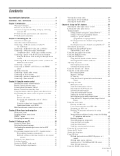
... Safety Instructions 3 Installation, Care, and Service 3 Chapter 1: Introduction 9 Welcome to Toshiba 9 Features of your new TV 9 Overview of steps for installing, setting up, and using your new TV 10 TV front and side panel controls and connections 11 TV back panel connections 12 Chapter 2: Connecting your TV 14 Overview of cable types 14 About the connection illustrations 14...
... Safety Instructions 3 Installation, Care, and Service 3 Chapter 1: Introduction 9 Welcome to Toshiba 9 Features of your new TV 9 Overview of steps for installing, setting up, and using your new TV 10 TV front and side panel controls and connections 11 TV back panel connections 12 Chapter 2: Connecting your TV 14 Overview of cable types 14 About the connection illustrations 14...
Owner's Manual - English
Page 8
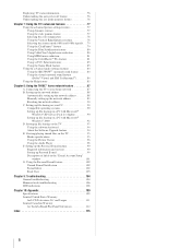
... troubleshooting 106 LED indications 108 Chapter 10: Appendix 109 Specifications 109 Limited United States Warranty for LCD Televisions 26" and Larger 111 Limited Canadian Warranty for Toshiba Brand Flat Panel Televisions 112 Index 115 8 Setting up the network address 88 Automatically setting up the network address...174; Virtual and SRS TruSurround 84 Using the Help feature 85 Chapter 8: Using the THINC™ home network feature 87 A. Connecting the TV to your PC 90 Compatible operating systems 90 Setting up file sharing on a PC with Microsoft® Windows® XP Service Pack ...
... troubleshooting 106 LED indications 108 Chapter 10: Appendix 109 Specifications 109 Limited United States Warranty for LCD Televisions 26" and Larger 111 Limited Canadian Warranty for Toshiba Brand Flat Panel Televisions 112 Index 115 8 Setting up the network address 88 Automatically setting up the network address...174; Virtual and SRS TruSurround 84 Using the Help feature 85 Chapter 8: Using the THINC™ home network feature 87 A. Connecting the TV to your PC 90 Compatible operating systems 90 Setting up file sharing on a PC with Microsoft® Windows® XP Service Pack ...
Owner's Manual - English
Page 10
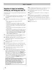
...e-mail, see Chapters 6 and 7. 13 For details on the TV. pages 31-39). 9 AFTER connecting all cables and devices to your LCD TV" (- When the TV is in standby mode, press POWER on the remote control. ... 3). • Place the TV in any power cords until the TV goes into the TV's channel memory (- If the TV stops responding to the controls on the remote control or TV control panel and you turn on the ... on the screen. • Place the TV far enough from walls and other objects to reset the TV. THIS TYPE OF DAMAGE IS NOT COVERED UNDER THE TOSHIBA WARRANTY. 3 Do not plug in a location...
...e-mail, see Chapters 6 and 7. 13 For details on the TV. pages 31-39). 9 AFTER connecting all cables and devices to your LCD TV" (- When the TV is in standby mode, press POWER on the remote control. ... 3). • Place the TV in any power cords until the TV goes into the TV's channel memory (- If the TV stops responding to the controls on the remote control or TV control panel and you turn on the ... on the screen. • Place the TV far enough from walls and other objects to reset the TV. THIS TYPE OF DAMAGE IS NOT COVERED UNDER THE TOSHIBA WARRANTY. 3 Do not plug in a location...

Owner's Manual - English
Page 11
...volume level. 10 INPUT - "Remote control effective range" on page 108 for 5 or more seconds to instantly close an on the TV's control panel functions as up/down/left/right menu navigation buttons. 6 MENU (ENTER) - Repeatedly press to turn off . When a menu is... on-screen, the MENU button on -screen menu. 8 CHANNEL Bb - Chapter 1: Introduction TV front and side panel controls and connections TV front Right side panel 4 8 POWER 5 9 6 7 10 Control panel 3 1 2 1 Green and Yellow LEDs Green = Power indicator Yellow = Power-On Mode indicator (- Press to...
...volume level. 10 INPUT - "Remote control effective range" on page 108 for 5 or more seconds to instantly close an on the TV's control panel functions as up/down/left/right menu navigation buttons. 6 MENU (ENTER) - Repeatedly press to turn off . When a menu is... on-screen, the MENU button on -screen menu. 8 CHANNEL Bb - Chapter 1: Introduction TV front and side panel controls and connections TV front Right side panel 4 8 POWER 5 9 6 7 10 Control panel 3 1 2 1 Green and Yellow LEDs Green = Power indicator Yellow = Power-On Mode indicator (- Press to...
Owner's Manual - English
Page 12
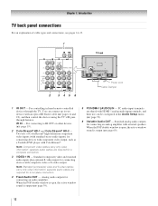
Chapter 1: Introduction TV back panel connections For an explanation of ColorStream® high-definition component video inputs (with standard stereo audio inputs) for connecting devices with component video output, such as a Toshiba DVD player with ColorStream®. Note: Standard (composite) video and S-video cables carry...audio input terminals are shared with an optical IR blaster cable (- Two sets of cable types and connections, see pages 14-23. 1 TV back 2 3 45 6 Power cord Cable Clamper 1 IR OUT - separate audio cables are required for connecting an analog amplifier with ...
Chapter 1: Introduction TV back panel connections For an explanation of ColorStream® high-definition component video inputs (with standard stereo audio inputs) for connecting devices with component video output, such as a Toshiba DVD player with ColorStream®. Note: Standard (composite) video and S-video cables carry...audio input terminals are shared with an optical IR blaster cable (- Two sets of cable types and connections, see pages 14-23. 1 TV back 2 3 45 6 Power cord Cable Clamper 1 IR OUT - separate audio cables are required for connecting an analog amplifier with ...
Owner's Manual - English
Page 15
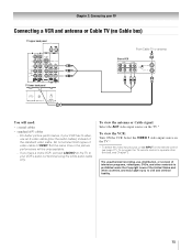
... source on the remote control (- Select the VIDEO 1 video input source on the TV.* * To select the video input source, press INPUT on the TV.* To view the VCR: Turn ON the VCR. To program the TV remote control to operate other countries, and may subject you have a mono VCR,..., videotapes, DVDs, and other materials is prohibited under the Copyright Laws of the standard video cable. Chapter 2: Connecting your TV Connecting a VCR and antenna or Cable TV (no Cable box) TV upper back panel From Cable TV or antenna Stereo VCR VIDEO AUDIO L R IN CH 3 CH 4 OUT L R IN from ANT OUT to...
... source on the remote control (- Select the VIDEO 1 video input source on the TV.* * To select the video input source, press INPUT on the TV.* To view the VCR: Turn ON the VCR. To program the TV remote control to operate other countries, and may subject you have a mono VCR,..., videotapes, DVDs, and other materials is prohibited under the Copyright Laws of the standard video cable. Chapter 2: Connecting your TV Connecting a VCR and antenna or Cable TV (no Cable box) TV upper back panel From Cable TV or antenna Stereo VCR VIDEO AUDIO L R IN CH 3 CH 4 OUT L R IN from ANT OUT to...
Owner's Manual - English
Page 16
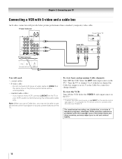
Chapter 2: Connecting your VCR's audio out terminal using the white audio cable only. TV upper back panel From Cable TV Cable box IN CH 3 CH 4 OUT TV lower back panel stereo VCR VIDEO AUDIO L R IN CH 3 CH 4 OUT L R IN from ANT OUT to change channels. If you have a mono VCR, connect L/MONO ...on the remote control (- Select the VIDEO 1 video input source on the TV.* * To select the video input source...
Chapter 2: Connecting your VCR's audio out terminal using the white audio cable only. TV upper back panel From Cable TV Cable box IN CH 3 CH 4 OUT TV lower back panel stereo VCR VIDEO AUDIO L R IN CH 3 CH 4 OUT L R IN from ANT OUT to change channels. If you have a mono VCR, connect L/MONO ...on the remote control (- Select the VIDEO 1 video input source on the TV.* * To select the video input source...
Owner's Manual - English
Page 17
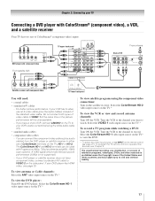
... VIDEO 1 at the same time or the picture performance will be used with component video TV lower back panel You will provide the best picture performance (1080p is prohibited under the Copyright Laws of video cable to your VCR's audio out terminal using the ..., and may subject you want to record. Y PB PR COMPONENT VIDEO S-VIDEO VIDEO OUT OUT DVD player with component video AUDIO OUT L R From satellite dish TV upper back panel From antenna Stereo VCR VIDEO AUDIO L R IN CH 3 CH 4 OUT L R IN from the DVD player or satellite receiver to VIDEO 2 on the...
... VIDEO 1 at the same time or the picture performance will be used with component video TV lower back panel You will provide the best picture performance (1080p is prohibited under the Copyright Laws of video cable to your VCR's audio out terminal using the ..., and may subject you want to record. Y PB PR COMPONENT VIDEO S-VIDEO VIDEO OUT OUT DVD player with component video AUDIO OUT L R From satellite dish TV upper back panel From antenna Stereo VCR VIDEO AUDIO L R IN CH 3 CH 4 OUT L R IN from the DVD player or satellite receiver to VIDEO 2 on the...
Owner's Manual - English
Page 18
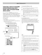
page 14) • other audio/video cables as Toshiba infrared remotecontrolled VCRs or DVD players) enclosed within an entertainment center or similar ...a rubber band and leave it remotely. To control the device(s): Point either the device's remote control or the TV remote control (that you also will need to use the device's remote control to operate the device, you previously... need : • dual-wand IR blaster cable (- The signal passes from device) TV upper back panel 18 Note: • If you use the TV's remote control to operate the TV. • The IR pass-through the...
page 14) • other audio/video cables as Toshiba infrared remotecontrolled VCRs or DVD players) enclosed within an entertainment center or similar ...a rubber band and leave it remotely. To control the device(s): Point either the device's remote control or the TV remote control (that you also will need to use the device's remote control to operate the device, you previously... need : • dual-wand IR blaster cable (- The signal passes from device) TV upper back panel 18 Note: • If you use the TV's remote control to operate the TV. • The IR pass-through the...
Owner's Manual - English
Page 19
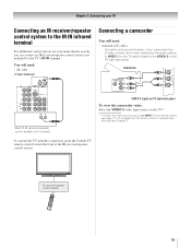
... (not included) VIDEO 2 inputs on TV right side panel To view the camcorder video: Select the VIDEO 2 video input source on the TV.* * To select the video input source, press INPUT on the TV right side panel. page 27). Chapter 2: Connecting your TV Connecting an IR receiver/repeater control system...your camcorder has S-video, connect an S-video cable (plus the audio cables) to the TV's IR IN terminal. IR receiver/repeater control system 19 To operate the TV with this connection, point the Toshiba TV remote control toward the front of the VIDEO 2 on the remote control (- For better...
... (not included) VIDEO 2 inputs on TV right side panel To view the camcorder video: Select the VIDEO 2 video input source on the TV.* * To select the video input source, press INPUT on the TV right side panel. page 27). Chapter 2: Connecting your TV Connecting an IR receiver/repeater control system...your camcorder has S-video, connect an S-video cable (plus the audio cables) to the TV's IR IN terminal. IR receiver/repeater control system 19 To operate the TV with this connection, point the Toshiba TV remote control toward the front of the VIDEO 2 on the remote control (- For better...

Owner's Manual - English
Page 20
...-to-DVI adapter cable (HDMI type A connector) per DVI device - Conventional HDMI/DVI cable may not work properly with the HDMI Logo ( ). - TV lower back panel HDMI device VIDEO AUDIO L R IN IN OUT L R HDMI OUT To view the HDMI device video: Select the HDMI 1, HDMI 2, or HDMI 3...other devices, see illustration). - Separate analog audio cables are not required (see page 109. See "Setting the HDMI™ audio mode" (- TV upper back panel TV lower back panel DVI device VIDEO AUDIO L R IN IN DVI / HDCP OUT OUT L R Note: To ensure that the HDMI or DVI device is reset...
...-to-DVI adapter cable (HDMI type A connector) per DVI device - Conventional HDMI/DVI cable may not work properly with the HDMI Logo ( ). - TV lower back panel HDMI device VIDEO AUDIO L R IN IN OUT L R HDMI OUT To view the HDMI device video: Select the HDMI 1, HDMI 2, or HDMI 3...other devices, see illustration). - Separate analog audio cables are not required (see page 109. See "Setting the HDMI™ audio mode" (- TV upper back panel TV lower back panel DVI device VIDEO AUDIO L R IN IN DVI / HDCP OUT OUT L R Note: To ensure that the HDMI or DVI device is reset...

Owner's Manual - English
Page 21
... the HDMI Logo ( ). However, Toshiba is limited to individual instruction manuals for those operations. page 75). • The connected devices must also be set the CE-Link Setup menu as regulated by the HDMI standard. • This feature is not liable for compatibility information. 21 TV lower back panel VIDEO AUDIO L R IN OUT...
... the HDMI Logo ( ). However, Toshiba is limited to individual instruction manuals for those operations. page 75). • The connected devices must also be set the CE-Link Setup menu as regulated by the HDMI standard. • This feature is not liable for compatibility information. 21 TV lower back panel VIDEO AUDIO L R IN OUT...

Owner's Manual - English
Page 22
... This connection allows you to use with an external Dolby® Digital decoder or other digital audio system LINE IN LR Optical Audio IN TV lower back panel Note: • Some audio systems may not be set to adjust the sound level. Note: To hear sound when using an external ... Range Control Reset No Auto Stereo English On Dolby Digital Compressed Done To control the audio: 1 Turn on page 66). LINE IN LR TV upper back panel Audio Digital Audio Selector Audio Settings Advanced Audio Settings Audio Setup 4 In the Optical Output Format field, select either Dolby Digital or PCM, ...
... This connection allows you to use with an external Dolby® Digital decoder or other digital audio system LINE IN LR Optical Audio IN TV lower back panel Note: • Some audio systems may not be set to adjust the sound level. Note: To hear sound when using an external ... Range Control Reset No Auto Stereo English On Dolby Digital Compressed Done To control the audio: 1 Turn on page 66). LINE IN LR TV upper back panel Audio Digital Audio Selector Audio Settings Advanced Audio Settings Audio Setup 4 In the Optical Output Format field, select either Dolby Digital or PCM, ...
Owner's Manual - English
Page 23
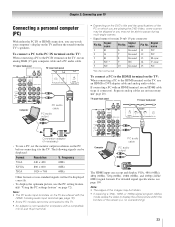
... the specifications of the PC on the TV are shared with the HDMI-1 analog audio input terminals (- Note: • The PC audio input terminals on which you are not necessary (- no overscanning). 23 TV upper back panel TV lower back panel Conversion adapter (if necessary) •... To use a PC, set the monitor output resolution on the TV, use an analog RGB (15-pin) computer cable and a PC audio cable....
... the specifications of the PC on the TV are shared with the HDMI-1 analog audio input terminals (- Note: • The PC audio input terminals on which you are not necessary (- no overscanning). 23 TV upper back panel TV lower back panel Conversion adapter (if necessary) •... To use a PC, set the monitor output resolution on the TV, use an analog RGB (15-pin) computer cable and a PC audio cable....

Owner's Manual - English
Page 24
...network, you will need: • standard Ethernet (RJ-45) cables • hub or switch TV lower back panel Hub or switch PC PC 24 Home Internet service. - Note: • The TV's home network feature is compatible with Microsoft® Windows® 2000, and the Home or ...which will allow access to Example #3 on the next page. • Does NOT require Internet/e-mail service. Chapter 2: Connecting your TV Connecting a home network The Toshiba Home Interactive Network Connection (THINC™) feature allows you use a router with built-in the United States and/or other countries....
...network, you will need: • standard Ethernet (RJ-45) cables • hub or switch TV lower back panel Hub or switch PC PC 24 Home Internet service. - Note: • The TV's home network feature is compatible with Microsoft® Windows® 2000, and the Home or ...which will allow access to Example #3 on the next page. • Does NOT require Internet/e-mail service. Chapter 2: Connecting your TV Connecting a home network The Toshiba Home Interactive Network Connection (THINC™) feature allows you use a router with built-in the United States and/or other countries....

Owner's Manual - English
Page 25
... cable (depending on your modem) • standard Ethernet (RJ-45) cables • router/switch[1] • modem (DSL or cable)[2] TV lower back panel Ethernet crossover PC cable Modem (DSL or cable) Router/switch [1] [2] [3] [3] Cable or phone jack [4] [3] PC [1] Your router/switch... may be part of your router. TV lower back panel Example #3: Connecting the TV to a home network with an Internet connection You will need : • coaxial or telephone cable (depending on your modem type...
... cable (depending on your modem) • standard Ethernet (RJ-45) cables • router/switch[1] • modem (DSL or cable)[2] TV lower back panel Ethernet crossover PC cable Modem (DSL or cable) Router/switch [1] [2] [3] [3] Cable or phone jack [4] [3] PC [1] Your router/switch... may be part of your router. TV lower back panel Example #3: Connecting the TV to a home network with an Internet connection You will need : • coaxial or telephone cable (depending on your modem type...

