

Owners Manual
Page 51
Introduction Connecting your TV Using the Remote Control Setting up your TV Troubleshooting Before calling a service technician, please check the following table for a possible cause of broadcast channels • The station may have broadcast difficulties. Poor reception of ... access signal input sources (Video1, Video2, Video3, ColorStream HD1/HD2) and/or Channels 3 and 4. • Check the VIDEO LOCK feature. Unable to the mode that the SPEAKERS function in the TV. • The remote control batteries may be dead. Try another channel. • Adjust the TINT and/or COLOR...
Introduction Connecting your TV Using the Remote Control Setting up your TV Troubleshooting Before calling a service technician, please check the following table for a possible cause of broadcast channels • The station may have broadcast difficulties. Poor reception of ... access signal input sources (Video1, Video2, Video3, ColorStream HD1/HD2) and/or Channels 3 and 4. • Check the VIDEO LOCK feature. Unable to the mode that the SPEAKERS function in the TV. • The remote control batteries may be dead. Try another channel. • Adjust the TINT and/or COLOR...

Service Manual
Page 2
GENERAL ADJUSTMENTS SPECIFIC INFORMATIONS TABLE OF CONTENTS CHAPTER 1 GENERAL ADJUSTMENTS SAFETY INSTRUCTIONS ...3 CRT ASSEMBLY REPLACEMENT AND MOUNTING 4 PICTURE TUBE COMPONENTS ADJUSTMENT ...6 REPLACEMENT OF THE CRT ...8 SERVICE MODE ...9 ELECTRICAL ADJUSTMENT ...11 CONVERGENCE ADJUSTMENT ...13 SCREEN AND MIRROR ALIGNMENTS ...15 CIRCUIT CHECKS ...16 CHAPTER 2 SPECIFIC INFORMATIONS SETTING & ADJUSTING DATA ...17 LOCATION OF CONTROLS ...18 ...
GENERAL ADJUSTMENTS SPECIFIC INFORMATIONS TABLE OF CONTENTS CHAPTER 1 GENERAL ADJUSTMENTS SAFETY INSTRUCTIONS ...3 CRT ASSEMBLY REPLACEMENT AND MOUNTING 4 PICTURE TUBE COMPONENTS ADJUSTMENT ...6 REPLACEMENT OF THE CRT ...8 SERVICE MODE ...9 ELECTRICAL ADJUSTMENT ...11 CONVERGENCE ADJUSTMENT ...13 SCREEN AND MIRROR ALIGNMENTS ...15 CIRCUIT CHECKS ...16 CHAPTER 2 SPECIFIC INFORMATIONS SETTING & ADJUSTING DATA ...17 LOCATION OF CONTROLS ...18 ...

Service Manual
Page 6
GENERAL ADJUSTMENTS SPECIFIC INFORMATIONS WARNING : BEFORE SERVICING THIS CHASSIS, READ THE "X-RAY RADIATION PRECAUTION", "SAFETY PRECAUTION" AND "PRODUCT SAFETY NOTICE" ON PAGE 3 OF THIS MANUAL. R, G, B FOCUS ADJUSTMENT 1. Then fasten the screw. (... to secure Lens Assembly. 2. Fig. PREPARATION Operate the receiver for Green and Blue colors. - 6 - a) and fasten the 4 screws to screen center. Select the adjustment mode. (See page 9.) 3. Adjust G centering magnet so that the cross-bar pat- Check whole quality of Lens Assembly which is finally fixed by 180˚ to...
GENERAL ADJUSTMENTS SPECIFIC INFORMATIONS WARNING : BEFORE SERVICING THIS CHASSIS, READ THE "X-RAY RADIATION PRECAUTION", "SAFETY PRECAUTION" AND "PRODUCT SAFETY NOTICE" ON PAGE 3 OF THIS MANUAL. R, G, B FOCUS ADJUSTMENT 1. Then fasten the screw. (... to secure Lens Assembly. 2. Fig. PREPARATION Operate the receiver for Green and Blue colors. - 6 - a) and fasten the 4 screws to screen center. Select the adjustment mode. (See page 9.) 3. Adjust G centering magnet so that the cross-bar pat- Check whole quality of Lens Assembly which is finally fixed by 180˚ to...

Service Manual
Page 9
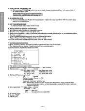
...(QA02) : Initialization of adjustment menu provides special functions. Service mode S Press Press Adjustment mode Item Data S (Service mode display) 3. ENTERING TO SERVICE MODE 1) Press MUTE button twice on TV set. 1/2 MUTE MUTE 2. KEY FUNCTION IN THE SERVICE MODE The following key entry during display of the self diagnostic... TV or Remote) MENU button (on TV) RECALL+Channel button on TV (s) RECALL+Channel button on TV. SERVICE MODE 2) Press MUTE button again to keep pressing. 3) While pressing the MUTE button, press MENU button on Remote Control. GENERAL ADJUSTMENTS SPECIFIC...
...(QA02) : Initialization of adjustment menu provides special functions. Service mode S Press Press Adjustment mode Item Data S (Service mode display) 3. ENTERING TO SERVICE MODE 1) Press MUTE button twice on TV set. 1/2 MUTE MUTE 2. KEY FUNCTION IN THE SERVICE MODE The following key entry during display of the self diagnostic... TV or Remote) MENU button (on TV) RECALL+Channel button on TV (s) RECALL+Channel button on TV. SERVICE MODE 2) Press MUTE button again to keep pressing. 3) While pressing the MUTE button, press MENU button on Remote Control. GENERAL ADJUSTMENTS SPECIFIC...
Service Manual
Page 10
... .......... The diagnosis will change the value of indication is indicated. (The order of priority of data in the service mode. Enter the service mode, then select any adjustment item above. SELF DIAGNOSTIC FUNCTION 1) Press "9" button on Remote Control during display of adjustment... mode. (See SETTING & ADJUSTING DATA on page 17) 5. SELECTING THE ADJUSTING ITEMS 1) Every pressing of CHANNEL s button in the service mode changes the adjustment items in the order of table-2. (t button for...
... .......... The diagnosis will change the value of indication is indicated. (The order of priority of data in the service mode. Enter the service mode, then select any adjustment item above. SELF DIAGNOSTIC FUNCTION 1) Press "9" button on Remote Control during display of adjustment... mode. (See SETTING & ADJUSTING DATA on page 17) 5. SELECTING THE ADJUSTING ITEMS 1) Every pressing of CHANNEL s button in the service mode changes the adjustment items in the order of table-2. (t button for...

Service Manual
Page 11
.... 5. VERTICAL POSITION (VCEN) 1. PICTURE POSITION (HPOS) 1. Check the picture with a jumper wire. 3. WIDTH (WID) 1. SUB-BRIGHTNESS (BRTC) 1. Enter the service mode, then select "BRTC" register. 4. oscillator) ADJUSTMENT PROCEDURE 1. Short the terminal "TP +9V " and the terminal " TP (Free run) " on scope. Connect ... the HEIGHT control on Remote Control. 3. Receive NTSC signal. 2. Adjust the data value so the belt of Hor. Enter the service mode, then select "SCOL". 5. Adjust the frequency to advance the data by PIC SIZE button on the MAIN board. 2. Blue 4....
.... 5. VERTICAL POSITION (VCEN) 1. PICTURE POSITION (HPOS) 1. Check the picture with a jumper wire. 3. WIDTH (WID) 1. SUB-BRIGHTNESS (BRTC) 1. Enter the service mode, then select "BRTC" register. 4. oscillator) ADJUSTMENT PROCEDURE 1. Short the terminal "TP +9V " and the terminal " TP (Free run) " on scope. Connect ... the HEIGHT control on Remote Control. 3. Receive NTSC signal. 2. Adjust the data value so the belt of Hor. Enter the service mode, then select "SCOL". 5. Adjust the frequency to advance the data by PIC SIZE button on the MAIN board. 2. Blue 4....

Service Manual
Page 12
...bottom of the best linearity. 4. Call up the adjustment mode display, then adjust the data of FOCUS PAC (page 8) clock- Adjust the data of items RDRV and BDRV Controls for low light area. 9. If necessary, perform again steps from service mode. 7. Receive cross-hatch pattern. 2. WHITE BALANCE (...RCUT) (GCUT) (BCUT) (RDRV) (BDRV) 1. Select the "FULL" mode by 8 steps. Press TV (ANT)/VIDEO button on TV or remote hand set. 2. ...
...bottom of the best linearity. 4. Call up the adjustment mode display, then adjust the data of FOCUS PAC (page 8) clock- Adjust the data of items RDRV and BDRV Controls for low light area. 9. If necessary, perform again steps from service mode. 7. Receive cross-hatch pattern. 2. WHITE BALANCE (...RCUT) (GCUT) (BCUT) (RDRV) (BDRV) 1. Select the "FULL" mode by 8 steps. Press TV (ANT)/VIDEO button on TV or remote hand set. 2. ...

Service Manual
Page 17
...-TINT SUB COLOR SUB-CONTRAST HORIZ. GENERAL ADJUSTMENTS SPECIFIC INFORMATIONS CHAPTER 2 SPECIFIC INFORMATIONS SETTING & ADJUSTING DATA SAFETY INSTRUCTIONS SERVICE MODE HIGH VOLTAGE AT ZERO BEAM: (A) MAX HIGH VOLTAGE: (B) Table-1 ADJUSTING ITEMS AND DATA IN THE SERVICE MODE: 50" 31.0 kV 32.5 kV Item Name of adjustment Preset Data EIOF R-Y BLACK (Q501) 20H ← EQOF...
...-TINT SUB COLOR SUB-CONTRAST HORIZ. GENERAL ADJUSTMENTS SPECIFIC INFORMATIONS CHAPTER 2 SPECIFIC INFORMATIONS SETTING & ADJUSTING DATA SAFETY INSTRUCTIONS SERVICE MODE HIGH VOLTAGE AT ZERO BEAM: (A) MAX HIGH VOLTAGE: (B) Table-1 ADJUSTING ITEMS AND DATA IN THE SERVICE MODE: 50" 31.0 kV 32.5 kV Item Name of adjustment Preset Data EIOF R-Y BLACK (Q501) 20H ← EQOF...


