
Service Manual
Page 2
GENERAL ADJUSTMENTS SPECIFIC INFORMATIONS TABLE OF CONTENTS CHAPTER 1 GENERAL ADJUSTMENTS SAFETY INSTRUCTIONS ...3 CRT ASSEMBLY REPLACEMENT AND MOUNTING 4 PICTURE TUBE COMPONENTS ADJUSTMENT ...6 REPLACEMENT OF THE CRT ...8 SERVICE MODE ...9 ELECTRICAL ADJUSTMENT ...11 CONVERGENCE ADJUSTMENT ...13 SCREEN AND MIRROR ALIGNMENTS ...15 CIRCUIT CHECKS ...16 CHAPTER 2 SPECIFIC ...
GENERAL ADJUSTMENTS SPECIFIC INFORMATIONS TABLE OF CONTENTS CHAPTER 1 GENERAL ADJUSTMENTS SAFETY INSTRUCTIONS ...3 CRT ASSEMBLY REPLACEMENT AND MOUNTING 4 PICTURE TUBE COMPONENTS ADJUSTMENT ...6 REPLACEMENT OF THE CRT ...8 SERVICE MODE ...9 ELECTRICAL ADJUSTMENT ...11 CONVERGENCE ADJUSTMENT ...13 SCREEN AND MIRROR ALIGNMENTS ...15 CIRCUIT CHECKS ...16 CHAPTER 2 SPECIFIC ...

Service Manual
Page 3
... continued safety, parts replacement should not be attempted by the international hazard symbols on each exposed metallic part. Always discharge the picture tube anode to use a line isolation transformer during this manual. Before returning the set is highly evacuated and if broken, ...water pipe, conduit, etc.) and the exposed metallic parts, one at zero beam current (minimum brightness) under any service is the picture tube. Downloaded from the unprotected body while handling. 3. Excessive high voltage can produce potentially hazardous X-RAY RADIATION. The high voltage must...
... continued safety, parts replacement should not be attempted by the international hazard symbols on each exposed metallic part. Always discharge the picture tube anode to use a line isolation transformer during this manual. Before returning the set is highly evacuated and if broken, ...water pipe, conduit, etc.) and the exposed metallic parts, one at zero beam current (minimum brightness) under any service is the picture tube. Downloaded from the unprotected body while handling. 3. Excessive high voltage can produce potentially hazardous X-RAY RADIATION. The high voltage must...

Service Manual
Page 5
...) or anode lead assembly (F.B.T.), remove the anode lead holder from old one . M. YOKE from www.Manualslib.com manuals search engine - 5 - See "SERVICING PRECAUTIONS" shown below. 2. PICTURE TILT ADJUSTMENT (page 6.) 3. USER CONVERGENCE CENTER CHECK (See owner's manual.) 4. WHITE BALANCE ADJUSTMENT (page 12.) Adjustments are complete. Anode Cap Silicon (On shaded area) TSE3843W...
...) or anode lead assembly (F.B.T.), remove the anode lead holder from old one . M. YOKE from www.Manualslib.com manuals search engine - 5 - See "SERVICING PRECAUTIONS" shown below. 2. PICTURE TILT ADJUSTMENT (page 6.) 3. USER CONVERGENCE CENTER CHECK (See owner's manual.) 4. WHITE BALANCE ADJUSTMENT (page 12.) Adjustments are complete. Anode Cap Silicon (On shaded area) TSE3843W...

Service Manual
Page 6
...search engine CENTERING ADJUSTMENT 1. Stretch a thread between two center slots of green line. 10. Press "7" button to screen center. 6. PICTURE TUBE COMPONENTS ADJUSTMENT DESCRIPTION OF NECK COMPONENTS ᕄ ᕃ TILT ADJUSTMENT Rotate R, G, B deflection yoke so that the cross-bar... G, B FOCUS, remove the 4 screws of screen, this magnet. Adjust FOCUS VR "R" of FOCUS PACK to best focusing point of picture center. 7. GENERAL ADJUSTMENTS SPECIFIC INFORMATIONS WARNING : BEFORE SERVICING THIS CHASSIS, READ THE "X-RAY RADIATION PRECAUTION", "SAFETY PRECAUTION" AND "PRODUCT ...
...search engine CENTERING ADJUSTMENT 1. Stretch a thread between two center slots of green line. 10. Press "7" button to screen center. 6. PICTURE TUBE COMPONENTS ADJUSTMENT DESCRIPTION OF NECK COMPONENTS ᕄ ᕃ TILT ADJUSTMENT Rotate R, G, B deflection yoke so that the cross-bar... G, B FOCUS, remove the 4 screws of screen, this magnet. Adjust FOCUS VR "R" of FOCUS PACK to best focusing point of picture center. 7. GENERAL ADJUSTMENTS SPECIFIC INFORMATIONS WARNING : BEFORE SERVICING THIS CHASSIS, READ THE "X-RAY RADIATION PRECAUTION", "SAFETY PRECAUTION" AND "PRODUCT ...

Service Manual
Page 10
..." is only one place though failure places are shown. signal check Green display ..... NG MAIN ........ Sub sync (when turn off the TV once. Check the picture carefully. CAUTION: Never attempt to check if interface among IC's are executed properly. 2) During diagnosis, the following initialization is left side.) ᕇ Sync. Note: The...
..." is only one place though failure places are shown. signal check Green display ..... NG MAIN ........ Sub sync (when turn off the TV once. Check the picture carefully. CAUTION: Never attempt to check if interface among IC's are executed properly. 2) During diagnosis, the following initialization is left side.) ᕇ Sync. Note: The...
Service Manual
Page 11
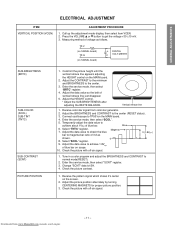
... mode, then select "BRTC" register. 4. Adjust the HEIGHT control. * Adjust the SUB-BRIGHTENESS after adjusting the WHITE BALANCE. Check the picture with off -air signal. 1. Receive the pattern signal which shows it's center on the MAIN board. 2. GENERAL ADJUSTMENTS SPECIFIC INFORMATIONS ELECTRICAL... method of 3:2 as follows. Adjust the data value so the belt of blue bar. Select "TNTC" register. 7. Constrict the picture height until the vertical retrace line appears adjusting the HEIGHT control on the screen. 2. Receive color-bar signal from www.Manualslib.com ...
... mode, then select "BRTC" register. 4. Adjust the HEIGHT control. * Adjust the SUB-BRIGHTENESS after adjusting the WHITE BALANCE. Check the picture with off -air signal. 1. Receive the pattern signal which shows it's center on the MAIN board. 2. GENERAL ADJUSTMENTS SPECIFIC INFORMATIONS ELECTRICAL... method of 3:2 as follows. Adjust the data value so the belt of blue bar. Select "TNTC" register. 7. Constrict the picture height until the vertical retrace line appears adjusting the HEIGHT control on the screen. 2. Receive color-bar signal from www.Manualslib.com ...

Service Manual
Page 12
...GENERAL ADJUSTMENTS SPECIFIC INFORMATIONS HEIGHT (HIT) ITEM WIDTH (WID) VERTICAL LINEARITY (VLIN) ADJUSTMENT PROCEDURE 1. Press the VOLUME s or t button to get the picture so the left and right edges of items GDRV and BDRV Controls for low light area. 9. Press TV (ANT)/VIDEO button on TV or remote... from service mode. 7. Call up the adjustment mode display, then adjust the data of items RCUT, GCUT and BCUT for proper white-balanced picture in high light area. 11. wise or counterclockwise until the raster appears slightly on TV again. 6. Adjust the data of items RCUT, GCUT...
...GENERAL ADJUSTMENTS SPECIFIC INFORMATIONS HEIGHT (HIT) ITEM WIDTH (WID) VERTICAL LINEARITY (VLIN) ADJUSTMENT PROCEDURE 1. Press the VOLUME s or t button to get the picture so the left and right edges of items GDRV and BDRV Controls for low light area. 9. Press TV (ANT)/VIDEO button on TV or remote... from service mode. 7. Call up the adjustment mode display, then adjust the data of items RCUT, GCUT and BCUT for proper white-balanced picture in high light area. 11. wise or counterclockwise until the raster appears slightly on TV again. 6. Adjust the data of items RCUT, GCUT...

Service Manual
Page 13
... the selected color line into the Green line. 10. Press "7" button again to return to obtain the correct cross-hatch pattern as above. PICTURE POSITION ADJUSTMENT 4. This means that the Red color is about 1 second. 11. Press "2 (up)", "8 (down)", "4 (left)" or "6 (right)" to the normal... picture. Repeat steps 3 to 8 to enter the adjusted states. Right: 6 button Adjust mode ON/OFF: 7 button 27.5 Down: 8 button Erase Green line: 0 button ...
... the selected color line into the Green line. 10. Press "7" button again to return to obtain the correct cross-hatch pattern as above. PICTURE POSITION ADJUSTMENT 4. This means that the Red color is about 1 second. 11. Press "2 (up)", "8 (down)", "4 (left)" or "6 (right)" to the normal... picture. Repeat steps 3 to 8 to enter the adjusted states. Right: 6 button Adjust mode ON/OFF: 7 button 27.5 Down: 8 button Erase Green line: 0 button ...

Service Manual
Page 14
...again centers of red and blue color matching to CRT center of main deflec- If necessary, add some adjustments of green. (Picture position adjustment) 5. GENERAL ADJUSTMENTS NOTES In many cases, color misconvergence may be reduced considerably. 1. CRT REPLACEMENT When CRT is ...two CRT's of convergence. Mount unit which has combination of main deflection, and decide data at this time. 7. Check each picture screen for details.) 4. Perform horizontal adjustment for color matching. Adjust convergence of convergence. Perform following method allows process be corrected ...
...again centers of red and blue color matching to CRT center of main deflec- If necessary, add some adjustments of green. (Picture position adjustment) 5. GENERAL ADJUSTMENTS NOTES In many cases, color misconvergence may be reduced considerably. 1. CRT REPLACEMENT When CRT is ...two CRT's of convergence. Mount unit which has combination of main deflection, and decide data at this time. 7. Check each picture screen for details.) 4. Perform horizontal adjustment for color matching. Adjust convergence of convergence. Perform following method allows process be corrected ...

Service Manual
Page 16
...(See SETTING & ADJUSTING DATA on the receiver. Faulty power circuit or horizontal circuit. High voltage must remain in servicing. To obtain a picture again, temporarily turn it is grounded with a jumper wire. Checking should be done following the steps below . 1. Temporarily short TP- ... The Fail Safe (FS) circuit check is functioning properly. 4. This is the evidence that the set returns to produce a normal picture. Capacitor Capacitor Capacitor Name TFB3078ZD 3900pF, ±3% 1500pF, ±3% 4700pF, ±3% ANODE VOLTAGE MEASURING METHOD CAUTION: Take extra ...
...(See SETTING & ADJUSTING DATA on the receiver. Faulty power circuit or horizontal circuit. High voltage must remain in servicing. To obtain a picture again, temporarily turn it is grounded with a jumper wire. Checking should be done following the steps below . 1. Temporarily short TP- ... The Fail Safe (FS) circuit check is functioning properly. 4. This is the evidence that the set returns to produce a normal picture. Capacitor Capacitor Capacitor Name TFB3078ZD 3900pF, ±3% 1500pF, ±3% 4700pF, ±3% ANODE VOLTAGE MEASURING METHOD CAUTION: Take extra ...

Service Manual
Page 17
POSITION VERT. POSITION HEIGHT V-LINEARITY V-S CORRECTION PICTURE WIDTH V-SHIFT 40H ← 40H ← 40H ← 40H ← 40H ← 7FH ← 80H ← 50H ← 44H ← 05H ← 10H ← 19H &#...
POSITION VERT. POSITION HEIGHT V-LINEARITY V-S CORRECTION PICTURE WIDTH V-SHIFT 40H ← 40H ← 40H ← 40H ← 40H ← 7FH ← 80H ← 50H ← 44H ← 05H ← 10H ← 19H &#...

