Toshiba 50A60 Support and Manuals
Get Help and Manuals for this Toshiba item

View All Support Options Below
Free Toshiba 50A60 manuals!
Problems with Toshiba 50A60?
Ask a Question
Free Toshiba 50A60 manuals!
Problems with Toshiba 50A60?
Ask a Question
Popular Toshiba 50A60 Manual Pages
Service Manual - Page 2
... 1 GENERAL ADJUSTMENTS SAFETY INSTRUCTIONS ...3 CRT ASSEMBLY REPLACEMENT AND MOUNTING 4 PICTURE TUBE COMPONENTS ADJUSTMENT ...6 REPLACEMENT OF THE CRT ...8 SERVICE MODE ...9 ELECTRICAL ADJUSTMENT ...11 CONVERGENCE ADJUSTMENT ...13 SCREEN AND MIRROR ALIGNMENTS ...15 CIRCUIT CHECKS ...16
CHAPTER 2 SPECIFIC INFORMATIONS SETTING & ADJUSTING DATA ...17 LOCATION OF CONTROLS ...18 PROGRAMMING CHANNEL...
Service Manual - Page 3

... potentially hazardous X-RAY RADIATION. For continued safety, parts replacement should not be obtained by a 0.15 µF, AC type capacitor, between the receiver and the AC line before handling the picture tube.
GENERAL ADJUSTMENTS
SPECIFIC INFORMATIONS
CHAPTER 1 GENERAL ADJUSTMENTS SAFETY INSTRUCTIONS
WARNING: BEFORE SERVICING THIS CHASSIS, READ THE "X-RAY RADIATION PRECAUTION...
Service Manual - Page 5

...illustrated.
ADJUSTING PROCEDURE IN REPLACING CRT 1. PICTURE TILT ADJUSTMENT (page 6.) 3. s Check the point of user static convergence, and result in a...SPECIFIC INFORMATIONS
SERVICING PRECAUTIONS
s Do not use a magnetized screw driver for R, G, B) Reverse the removal procedures except the followings. 1. s When replacing the anode cap assembly (CRT) or anode lead assembly (F.B.T.), remove...
Service Manual - Page 6

... Blue colors.
- 6 - In order to adjust the fastening screw (Fig.
Before adjusting the R, G, B FOCUS, remove the 4
screws of screen
edge (top and bottom, left and right).
ᕃ Deflection yoke and convergence yoke The position on the Remote Control to be used for at least 5 minutes. a) and fasten the 4 screws to display the built-in cross-hatch...
Service Manual - Page 8

... CAP
Fig.
RUBBER BOOT IS ATTACHED TO ANODE LEAD AND ANODE CAP.
2. b
Cut here rubber boot and lead together to detach Lead Holder. GENERAL ADJUSTMENTS
SPECIFIC INFORMATIONS
REPLACEMENT OF THE CRT
Service parts are as shown in figure below, and put it on new lead.
The contents of the...
Service Manual - Page 9

... SERVICE MODE The following key entry during display of the self diagnostic data:
TV (ANT)/VIDEO button (on TV) Channel s/t (on TV or Remote) Volume s/t (on TV or Remote) MENU button (on TV) RECALL+Channel button on TV (s) RECALL+Channel button on Remote Control. Service mode
S
Press
Press
Adjustment mode
S (Service mode display)
Item Data
3. GENERAL ADJUSTMENTS
SPECIFIC INFORMATIONS...
Service Manual - Page 10

... (when turn off the TV once. SELECTING THE ADJUSTING ITEMS 1) Every pressing of CHANNEL s button in the service mode changes the adjustment items in the range from www.Manualslib.com manuals search engine
- 10 - s INITIALIZATION OF MEMORY DATA OF QA02 After replacing QA02, the following displays are plural.
Check the picture carefully. NG
MAIN ........ The...
Service Manual - Page 11
... METER
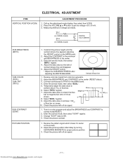
SUB-BRIGHTNESS (BRTC)
SUB-COLOR (SCOL) SUB-TINT (TNTC)
SUB-CONTRAST (SCNT)
PICTURE POSITION
1. Check the picture with off -air signal.
Constrict the picture height until the vertical retrace line appears adjusting the HEIGHT control on the screen.
2. Enter the service mode, then select "BRTC" register.
4. Adjust the BRIGHTNESS and CONTRAST to TP501on the MAIN...
Service Manual - Page 12

...SCREEN volume of raster begins to low light. 8. Adjust the contrast to the maximum to make white picture to lack. 3. Adjust the data of the best linearity. 4.
Press RESET button on TV again. 6. Press TV (ANT)/VIDEO button on TV or remote hand set. 2. Downloaded from service... white-balanced picture in both low and high light areas. Exit from www.Manualslib.com manuals search engine...
Service Manual - Page 14

... to CRT center of each screen picture for details.) 4.
SPECIFIC INFORMATIONS
Downloaded from www.Manualslib.com manuals search engine
- 14 - Do not move green one at the most precise screen comparing to initial adjusting values. After convergence adjustment of green.
(Picture position adjustment) 5.
Replace two CRT's of convergence.
Replace the memory (Q713) on...
Service Manual - Page 16

...Troubleshooting Guide for the final check in this state even after replacing. Connect an accurate high voltage meter to normal operation when pin 12 of the rubber cover before disconnecting the cable.
4. Vary the BRIGHTNESS to both extremes to produce a normal picture.... Checking should be done following parts fail, check the High Voltage after removing the jumper wire.
Then turn ...
Service Manual - Page 19

...
PIP CH
STOP SOURCE PLAY PIP
REC TV/VCR REW FF
STILL LOCATE SWAP
RECALL POWER
TIMER TV/VIDEO CHANNEL s/t
VOLUME s/t CH RTN MENU
PIP CH s FAV s
s/t/T/S EXIT
PIP functions (For "TV" and "CABLE" modes)
Downloaded from www.Manualslib.com manuals search engine
- 19 - GENERAL ADJUSTMENTS
SPECIFIC INFORMATIONS
Remote Control
LIGHT TV/CABLE/VCR switch Set to "TV" to control the TV.
Service Manual - Page 22

... Light Box Removal
A266
A401
5 screws
A424 3 screws
3 screws
A160
1 screw (A150)
3 screws 3 screws
(A110)
- 24 - 1 Speaker Grille Removal
A101
2 Control Panel Removal
A103
A102 5 Shield Plate, Lens Removal
4 screws K111 K112 K113
A221 (A322)
A213 A224
A202
A126 A127
A268
6 Mirror Removal
5 screws
A152
K601
A269 4 screws
- 23 -
Downloaded from www.Manualslib.com manuals search...
Service Manual - Page 23

...part number must be used when ordering parts, in order to assist in the parts list. The mounting position of replacements...Part No.
Do not degrade the safety of these components, read carefully the PRODUCT SAFETY NOTICE. Models : 50A60....com manuals search engine
- 25 - Part No. GENERAL ADJUSTMENTS
SPECIFIC INFORMATIONS
CHASSIS REPLACEMENT PARTS LIST
WARNING: BEFORE SERVICING THIS CHASSIS...
Service Manual - Page 49

... CENTER CHANNEL INPUT 300 mV(rms) (30% modulation equivalent, 10 kohm)
Dimension (W/H/D)
Mass
50A60 42-1/4 x 50-5/8 x 20-13/16 inches 217 lbs
(1,073 x 1,284 x 529 mm)
(98.6 kg)
SUPPLIED ACCESSORIES
Remote Control with 2 size "AA" alkaline batteries
*Please refer to owner's manual in detail.
C-INPUT: 0.286 V(p-p) (burst signal), 75 ohm
VIDEO/AUDIO INPUT VIDEO...
Toshiba 50A60 Reviews
We have not received any reviews for Toshiba yet.