

Service Manual
Page 1
FILE NO. 020-200012 SERVICE MANUAL COLOR TELEVISION N0NSP Chassis 50A60, 50A50 (TAC0050) (TAC0051) 55A60, 61A60 (TAC0052) (TAC0053) Downloaded from www.Manualslib.com manuals search engine PUBLISHED IN JAPAN, May., 2000 S
FILE NO. 020-200012 SERVICE MANUAL COLOR TELEVISION N0NSP Chassis 50A60, 50A50 (TAC0050) (TAC0051) 55A60, 61A60 (TAC0052) (TAC0053) Downloaded from www.Manualslib.com manuals search engine PUBLISHED IN JAPAN, May., 2000 S
Service Manual
Page 2
... CHASSIS REPLACEMENT PARTS LIST ...25 PC BOARDS BOTTOM VIEW ...41 TERMINAL VIEW OF TRANSISTORS ...51 SPECIFICATIONS ...53 APPENDIX: CIRCUIT DIAGRAM Downloaded from www.Manualslib.com manuals search engine - 2 -
... CHASSIS REPLACEMENT PARTS LIST ...25 PC BOARDS BOTTOM VIEW ...41 TERMINAL VIEW OF TRANSISTORS ...51 SPECIFICATIONS ...53 APPENDIX: CIRCUIT DIAGRAM Downloaded from www.Manualslib.com manuals search engine - 2 -

Service Manual
Page 3
... (A) kV at the AC outlet and repeat AC voltage measurements for high voltage (A), (B). (See SETTING & ADJUSTING DATA on this manual carefully. Measure the AC voltage across the combination of X-RAY RADIATION in this TV receiver is equipped with the necessary precautions on page... ground such as ; When replacing a chassis in this probe on the receiver. 2. The use a line isolation transformer during this manual. Each time the receiver is properly functioning, following are identified in the cabinet, always be checked to determine that all the protective devices...
... (A) kV at the AC outlet and repeat AC voltage measurements for high voltage (A), (B). (See SETTING & ADJUSTING DATA on this manual carefully. Measure the AC voltage across the combination of X-RAY RADIATION in this TV receiver is equipped with the necessary precautions on page... ground such as ; When replacing a chassis in this probe on the receiver. 2. The use a line isolation transformer during this manual. Each time the receiver is properly functioning, following are identified in the cabinet, always be checked to determine that all the protective devices...

Service Manual
Page 4
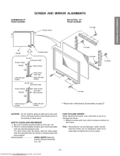
Coil 4 Screws CRT DRIVE Board CRT Mounting Deflection Yoke and Conver Yoke Lens and Neck Components View Downloaded from www.Manualslib.com manuals search engine - 4 - R G B 8 o'clock 4 o'clock Attention Serviceman The Hex Head Bolts with Springs. (see sketch) used on CRT assembly, are "NOT" Adjustment Screws DO NOT LOOSEN-...
Coil 4 Screws CRT DRIVE Board CRT Mounting Deflection Yoke and Conver Yoke Lens and Neck Components View Downloaded from www.Manualslib.com manuals search engine - 4 - R G B 8 o'clock 4 o'clock Attention Serviceman The Hex Head Bolts with Springs. (see sketch) used on CRT assembly, are "NOT" Adjustment Screws DO NOT LOOSEN-...

Service Manual
Page 5
...R, G, B) 1. Anode Cable should be replaced with new one and attach the holder again to new anode lead. USER CONVERGENCE CENTER CHECK (See owner's manual.) 4. CENTERING ADJUSTMENT (page 6.) 5. WHITE BALANCE ADJUSTMENT (page 12.) Adjustments are complete. See "SERVICING PRECAUTIONS" shown below. 2. FOCUS ADJUSTMENT (page 6.)..., and result in a straight line, if it is winding, please revise it. Remove CRT Assembly from www.Manualslib.com manuals search engine - 5 - Install silicon (T461B) to avoid magnetization of Deflection Yoke and Velocity Modulation Coil to the CRT,...
...R, G, B) 1. Anode Cable should be replaced with new one and attach the holder again to new anode lead. USER CONVERGENCE CENTER CHECK (See owner's manual.) 4. CENTERING ADJUSTMENT (page 6.) 5. WHITE BALANCE ADJUSTMENT (page 12.) Adjustments are complete. See "SERVICING PRECAUTIONS" shown below. 2. FOCUS ADJUSTMENT (page 6.)..., and result in a straight line, if it is winding, please revise it. Remove CRT Assembly from www.Manualslib.com manuals search engine - 5 - Install silicon (T461B) to avoid magnetization of Deflection Yoke and Velocity Modulation Coil to the CRT,...

Service Manual
Page 6
...WARNING : BEFORE SERVICING THIS CHASSIS, READ THE "X-RAY RADIATION PRECAUTION", "SAFETY PRECAUTION" AND "PRODUCT SAFETY NOTICE" ON PAGE 3 OF THIS MANUAL. CENTERING ADJUSTMENT 1. In order to get maximum margin of user convergence control for center convergence adjustment. R, G, B FOCUS ADJUSTMENT 1. a) ... Then turn around the Lens Assembly by this magnet have to adjust the fastening screw (Fig. Fig. Downloaded from www.Manualslib.com manuals search engine Press "7" button to screen center. 6. Then fasten the screw. (See Fig. Repeat steps 3 to screen center. tern...
...WARNING : BEFORE SERVICING THIS CHASSIS, READ THE "X-RAY RADIATION PRECAUTION", "SAFETY PRECAUTION" AND "PRODUCT SAFETY NOTICE" ON PAGE 3 OF THIS MANUAL. CENTERING ADJUSTMENT 1. In order to get maximum margin of user convergence control for center convergence adjustment. R, G, B FOCUS ADJUSTMENT 1. a) ... Then turn around the Lens Assembly by this magnet have to adjust the fastening screw (Fig. Fig. Downloaded from www.Manualslib.com manuals search engine Press "7" button to screen center. 6. Then fasten the screw. (See Fig. Repeat steps 3 to screen center. tern...

Service Manual
Page 7
GENERAL ADJUSTMENTS LOCATION OF SCREEN AND FOCUS VR'S SCREEN VR FOCUS VR RGB SPECIFIC INFORMATIONS Downloaded from www.Manualslib.com manuals search engine - 7 -
GENERAL ADJUSTMENTS LOCATION OF SCREEN AND FOCUS VR'S SCREEN VR FOCUS VR RGB SPECIFIC INFORMATIONS Downloaded from www.Manualslib.com manuals search engine - 7 -

Service Manual
Page 8
... OLD ANODE LEAD or ANODE CAP Fig. When replacing Anode Lead or Anode Cap with new one, remove Lead Holder from www.Manualslib.com manuals search engine - 8 - NOTE : THE LEAD HOLDER IS ATTACHED TO TPA5007 (Z450), BUT IS NOT ATTACHED TO ANODE LEAD AND ANODE ...TPA5007 LOCK LEAD HOLDER Fig. Downloaded from old lead as follows. The contents of the parts are provided for each R, G and B. HITACHI CRT 50A50 50A60 55A60 61A60 R 23796001 23005114 23005242 23005249 G 23005397 23005115 ↑ ↑ B 23796003 ↑ ↑ 23796486 REPLACEMENT OF HIGH VOLTAGE CABLE ANODE LEAD...
... OLD ANODE LEAD or ANODE CAP Fig. When replacing Anode Lead or Anode Cap with new one, remove Lead Holder from www.Manualslib.com manuals search engine - 8 - NOTE : THE LEAD HOLDER IS ATTACHED TO TPA5007 (Z450), BUT IS NOT ATTACHED TO ANODE LEAD AND ANODE ...TPA5007 LOCK LEAD HOLDER Fig. Downloaded from old lead as follows. The contents of the parts are provided for each R, G and B. HITACHI CRT 50A50 50A60 55A60 61A60 R 23796001 23005114 23005242 23005249 G 23005397 23005115 ↑ ↑ B 23796003 ↑ ↑ 23796486 REPLACEMENT OF HIGH VOLTAGE CABLE ANODE LEAD...

Service Manual
Page 9
... : Convergence adj : Test audio signal ON/OFF (1kHz) : Self diagnostic display : 1 button 2 button 3 button 4 button 5 button 6 button 7 button 8 button 9 button Downloaded from www.Manualslib.com manuals search engine - 9 -
... : Convergence adj : Test audio signal ON/OFF (1kHz) : Self diagnostic display : 1 button 2 button 3 button 4 button 5 button 6 button 7 button 8 button 9 button Downloaded from www.Manualslib.com manuals search engine - 9 -

Service Manual
Page 10
... (current limiter) . . . . Press and hold the RECALL button on the Remote, then press the CHANNEL s button on the owner's manual. Normal Red display ........ The variable range depends on page 17) 5. When repair of a failure place finishes, the next failure place is required... THE ADJUSTING ITEMS 1) Every pressing of CHANNEL s button in the service mode changes the adjustment items in the range from www.Manualslib.com manuals search engine - 10 - The initialization of adjustment mode. (See SETTING & ADJUSTING DATA on the adjusting item. 6. ADJUSTING THE DATA 1)...
... (current limiter) . . . . Press and hold the RECALL button on the Remote, then press the CHANNEL s button on the owner's manual. Normal Red display ........ The variable range depends on page 17) 5. When repair of a failure place finishes, the next failure place is required... THE ADJUSTING ITEMS 1) Every pressing of CHANNEL s button in the service mode changes the adjustment items in the range from www.Manualslib.com manuals search engine - 10 - The initialization of adjustment mode. (See SETTING & ADJUSTING DATA on the adjusting item. 6. ADJUSTING THE DATA 1)...
Service Manual
Page 11
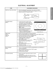
.... 3. Press the VOLUME s or t button to the center (RESET status). 3. Check the picture with off -air signal. 1. Receive color-bar signal from www.Manualslib.com manuals search engine - 11 - Temporarily adjust the data value to TP501on the MAIN board. 4. Enter the service mode, then select "BRTC" register. 4. Connect oscilloscope to achieve...
.... 3. Press the VOLUME s or t button to the center (RESET status). 3. Check the picture with off -air signal. 1. Receive color-bar signal from www.Manualslib.com manuals search engine - 11 - Temporarily adjust the data value to TP501on the MAIN board. 4. Enter the service mode, then select "BRTC" register. 4. Connect oscilloscope to achieve...

Service Manual
Page 12
... SPECIFIC INFORMATIONS HEIGHT (HIT) ITEM WIDTH (WID) VERTICAL LINEARITY (VLIN) ADJUSTMENT PROCEDURE 1. Press TV (ANT)/VIDEO button on TV again. 6. Exit from www.Manualslib.com manuals search engine - 12 - Press RESET button on the CRT through the each lens, and leave them. (Look into the lens in order to advance the...
... SPECIFIC INFORMATIONS HEIGHT (HIT) ITEM WIDTH (WID) VERTICAL LINEARITY (VLIN) ADJUSTMENT PROCEDURE 1. Press TV (ANT)/VIDEO button on TV again. 6. Exit from www.Manualslib.com manuals search engine - 12 - Press RESET button on the CRT through the each lens, and leave them. (Look into the lens in order to advance the...

Service Manual
Page 13
... 4 P = 84 x12 (50") 92 x12 (55") 103 x12 (61") 27.5 4 The pattern includes three colors (R, G, B). Adjustment around cursor can be erased from www.Manualslib.com manuals search engine - 13 - Press "5" button to be done. 3. Press "2", "8", "4", "6" buttons to move the cursor to other point to make the cursor blinking. 7. PICTURE POSITION ADJUSTMENT...
... 4 P = 84 x12 (50") 92 x12 (55") 103 x12 (61") 27.5 4 The pattern includes three colors (R, G, B). Adjustment around cursor can be erased from www.Manualslib.com manuals search engine - 13 - Press "5" button to be done. 3. Press "2", "8", "4", "6" buttons to move the cursor to other point to make the cursor blinking. 7. PICTURE POSITION ADJUSTMENT...

Service Manual
Page 14
..., red and blue with memory on . Check each screen picture for slight disparity of color and picture size. SPECIFIC INFORMATIONS Downloaded from www.Manualslib.com manuals search engine - 14 - ment, pushing towards vertical or horizontal direction. 3. Rotating centering magnet, adjust CRT centers of red and blue to CRT center of main...
..., red and blue with memory on . Check each screen picture for slight disparity of color and picture size. SPECIFIC INFORMATIONS Downloaded from www.Manualslib.com manuals search engine - 14 - ment, pushing towards vertical or horizontal direction. 3. Rotating centering magnet, adjust CRT centers of red and blue to CRT center of main...
Service Manual
Page 15
... wipe away the black print on the surface. HOW TO CLEAN LENS AND MIRROR 1. tured by Edmund Scientific Co.), etc. Downloaded from www.Manualslib.com manuals search engine - 15 - Be sure to avoid finger-prints on the screen. CAUTION : Do not hold the optical system parts (lens and mirror) with bare...
... wipe away the black print on the surface. HOW TO CLEAN LENS AND MIRROR 1. tured by Edmund Scientific Co.), etc. Downloaded from www.Manualslib.com manuals search engine - 15 - Be sure to avoid finger-prints on the screen. CAUTION : Do not hold the optical system parts (lens and mirror) with bare...

Service Manual
Page 16
... to table-1 for the final check in this high voltage. Turn the receiver on page17) NO Defective Fail Safe Circuit Downloaded from www.Manualslib.com manuals search engine - 16 - Measure high voltage at the point where the cable enters the FBT. 2. Connect an accurate high voltage meter to produce a normal picture...
... to table-1 for the final check in this high voltage. Turn the receiver on page17) NO Defective Fail Safe Circuit Downloaded from www.Manualslib.com manuals search engine - 16 - Measure high voltage at the point where the cable enters the FBT. 2. Connect an accurate high voltage meter to produce a normal picture...

Service Manual
Page 17
... 41H ← VCEN V POSITION 81H ← TVOP TV OPTION 00H ← Table-2 CIRCUIT CHECKS FBT DETECTION VOLTAGE (C) 24.5V Table-3 Downloaded from www.Manualslib.com manuals search engine - 17 - POSITION HEIGHT V-LINEARITY V-S CORRECTION PICTURE WIDTH V-SHIFT 40H ← 40H ← 40H ← 40H ← 40H ← 7FH ← 80H ← 50H...
... 41H ← VCEN V POSITION 81H ← TVOP TV OPTION 00H ← Table-2 CIRCUIT CHECKS FBT DETECTION VOLTAGE (C) 24.5V Table-3 Downloaded from www.Manualslib.com manuals search engine - 17 - POSITION HEIGHT V-LINEARITY V-S CORRECTION PICTURE WIDTH V-SHIFT 40H ← 40H ← 40H ← 40H ← 40H ← 7FH ← 80H ← 50H...

Service Manual
Page 19
... POWER TIMER TV/VIDEO CHANNEL s/t VOLUME s/t CH RTN MENU PIP CH s FAV s s/t/T/S EXIT PIP functions (For "TV" and "CABLE" modes) Downloaded from www.Manualslib.com manuals search engine - 19 - MUTE Channel Number C. GENERAL ADJUSTMENTS SPECIFIC INFORMATIONS Remote Control LIGHT TV/CABLE/VCR switch Set to "TV" to control the TV.
... POWER TIMER TV/VIDEO CHANNEL s/t VOLUME s/t CH RTN MENU PIP CH s FAV s s/t/T/S EXIT PIP functions (For "TV" and "CABLE" modes) Downloaded from www.Manualslib.com manuals search engine - 19 - MUTE Channel Number C. GENERAL ADJUSTMENTS SPECIFIC INFORMATIONS Remote Control LIGHT TV/CABLE/VCR switch Set to "TV" to control the TV.

Service Manual
Page 20
... s or t to make sure the channel programming has been done properly. You have now completed the channel programming. Downloaded from www.Manualslib.com manuals search engine - 20 - ADD/ERASE function After performing the CH PROGRAM function, you can add or erase specific channels. 1 Select the channel ... the TV tunes in detail. To add the channel press the button until "TV/CABLE" is highlighted. 5 Repeat steps 1 to owner's manual in when you utilize both ANT-1 and ANT-2 terminals for some model, perform programming channels for other channels. Note: If you press the ...
... s or t to make sure the channel programming has been done properly. You have now completed the channel programming. Downloaded from www.Manualslib.com manuals search engine - 20 - ADD/ERASE function After performing the CH PROGRAM function, you can add or erase specific channels. 1 Select the channel ... the TV tunes in detail. To add the channel press the button until "TV/CABLE" is highlighted. 5 Repeat steps 1 to owner's manual in when you utilize both ANT-1 and ANT-2 terminals for some model, perform programming channels for other channels. Note: If you press the ...

Service Manual
Page 22
1 Speaker Grille Removal A101 2 Control Panel Removal A103 A102 5 Shield Plate, Lens Removal 4 screws K111 K112 K113 A221 (A322) A213 A224 A202 A126 A127 A268 6 Mirror Removal 5 screws A152 K601 A269 4 screws - 23 - MECHANICAL DISASSEMBLY 3 Front Mask Removal A201 K502 K501 (K511) 4 screws 7 Back Board Removal 4 Mask Removal A267 A201 A266 A265 8 Light Box Removal A266 A401 5 screws A424 3 screws 3 screws A160 1 screw (A150) 3 screws 3 screws (A110) - 24 - Downloaded from www.Manualslib.com manuals search engine
1 Speaker Grille Removal A101 2 Control Panel Removal A103 A102 5 Shield Plate, Lens Removal 4 screws K111 K112 K113 A221 (A322) A213 A224 A202 A126 A127 A268 6 Mirror Removal 5 screws A152 K601 A269 4 screws - 23 - MECHANICAL DISASSEMBLY 3 Front Mask Removal A201 K502 K501 (K511) 4 screws 7 Back Board Removal 4 Mask Removal A267 A201 A266 A265 8 Light Box Removal A266 A401 5 screws A424 3 screws 3 screws A160 1 screw (A150) 3 screws 3 screws (A110) - 24 - Downloaded from www.Manualslib.com manuals search engine


