
Printable Spec Sheet
Page 1
...-Screen Display • Off/Sleep Timer ADVANTAGE TOSHIBA >> HD Dynamic Contrast feature continually analyzes picture information and enhances those parts of digital video noise reduction, and the appropriate sharpness adjustment to Toshiba's fixed pixel picture quality; 32" DIAGONAL THEATERWIDE® LCD HD MONTIOR 32HL84 KEY FEATURES • 720p (1366 x 768) True HD Display with Built-in a sharper, deeper image...
...-Screen Display • Off/Sleep Timer ADVANTAGE TOSHIBA >> HD Dynamic Contrast feature continually analyzes picture information and enhances those parts of digital video noise reduction, and the appropriate sharpness adjustment to Toshiba's fixed pixel picture quality; 32" DIAGONAL THEATERWIDE® LCD HD MONTIOR 32HL84 KEY FEATURES • 720p (1366 x 768) True HD Display with Built-in a sharper, deeper image...

Printable Spec Sheet
Page 2
....01) dbx is a trademark of Carillon Electronics Corporation. CableClear, SurfLock, HD Window, TheaterLink, and GameTimer are registered trademarks of Toshiba America Consumer Products. Product design and specification subject to change or modification without notice. 32HL84 S P E C I F I C AT I O N S VIDEO AUDIO CONVENIENCE Series TheaterWide® HD LCD TV Screen Size 32" Diagonal Wide* Panel Resolution 1366 x 768 Contrast 800:1 Brightness 500cd...
....01) dbx is a trademark of Carillon Electronics Corporation. CableClear, SurfLock, HD Window, TheaterLink, and GameTimer are registered trademarks of Toshiba America Consumer Products. Product design and specification subject to change or modification without notice. 32HL84 S P E C I F I C AT I O N S VIDEO AUDIO CONVENIENCE Series TheaterWide® HD LCD TV Screen Size 32" Diagonal Wide* Panel Resolution 1366 x 768 Contrast 800:1 Brightness 500cd...

Installation Guide - English
Page 1
... and 020-200405 for any resulting damages and may be complied with before returning the equipment to possible injury. ©2005 TOSHIBA AMERICA CONSUMER PRODUCTS, LLC Hideto Kitamura Manager International Customer Service & Support Dept. Servicers who defeat safety features or fail to ... Dept. [34F-A] 1-1,SHIBAURA 1-CHOME, MINATO-KU TOKYO 105-8001,JAPAN PHONE:(03)3457-3536 FACSIMILE:(03)5444-9408 SERVICE INSTRUCTION Product: LCD TV Model: 26/32HL84, 26/32WL46B/G/C/A/E/R/T Corrective Action: Backlight Lamp unit as a service part File No.01C2005002R Date: Mar.11,2005 Rank: C Part No....
... and 020-200405 for any resulting damages and may be complied with before returning the equipment to possible injury. ©2005 TOSHIBA AMERICA CONSUMER PRODUCTS, LLC Hideto Kitamura Manager International Customer Service & Support Dept. Servicers who defeat safety features or fail to ... Dept. [34F-A] 1-1,SHIBAURA 1-CHOME, MINATO-KU TOKYO 105-8001,JAPAN PHONE:(03)3457-3536 FACSIMILE:(03)5444-9408 SERVICE INSTRUCTION Product: LCD TV Model: 26/32HL84, 26/32WL46B/G/C/A/E/R/T Corrective Action: Backlight Lamp unit as a service part File No.01C2005002R Date: Mar.11,2005 Rank: C Part No....

Installation Guide - English
Page 2
... Bottom view INV board (HOT) side Return FFC INV board (GND) side C board INV cover C board cover Flat cables Ferrite cores Service Instruction 2004 LCD Television Page 1 of 12 Follow the included replacement procedures when replacing these ferrite cores, as excessive force may cause damage. Backlight lamp units are attached ...
... Bottom view INV board (HOT) side Return FFC INV board (GND) side C board INV cover C board cover Flat cables Ferrite cores Service Instruction 2004 LCD Television Page 1 of 12 Follow the included replacement procedures when replacing these ferrite cores, as excessive force may cause damage. Backlight lamp units are attached ...

Installation Guide - English
Page 3
Remove the two screws securing the C board. Use caution when removing the ferrite cores, as excessive force may cause damage. Remove the two screws securing the C board cover. 2-2. Service Instruction 2004 LCD Television Page 2 of 12 2. Remove the C board and connectors, using caution to remove the ferrite cores. Removing C Board Cover and C Board 2.1.
Remove the two screws securing the C board. Use caution when removing the ferrite cores, as excessive force may cause damage. Remove the two screws securing the C board cover. 2-2. Service Instruction 2004 LCD Television Page 2 of 12 2. Remove the C board and connectors, using caution to remove the ferrite cores. Removing C Board Cover and C Board 2.1.

Installation Guide - English
Page 4
Disconnect the seven lamp unit connectors and remove the three screws securing the INV board (HOT side). 3-4. Service Instruction 2004 LCD Television Page 3 of 12 Remove the return FFC connected to the INV board. 3-2. Disconnect the seven lamp unit connectors and remove the seven screws securing the INV board (GND side). Remove the three screws securing the INV cover. 3-3. 3. Removing INV Cover and INV Board (HOT Side / GND Side) 3-1.
Disconnect the seven lamp unit connectors and remove the three screws securing the INV board (HOT side). 3-4. Service Instruction 2004 LCD Television Page 3 of 12 Remove the return FFC connected to the INV board. 3-2. Disconnect the seven lamp unit connectors and remove the seven screws securing the INV board (GND side). Remove the three screws securing the INV cover. 3-3. 3. Removing INV Cover and INV Board (HOT Side / GND Side) 3-1.

Installation Guide - English
Page 5
Service Instruction 2004 LCD Television Page 4 of 12 Removing Panel Unit and Lamp Holder 4-1. Remove the six screws securing the lamp holder. Remove the 20 screws securing the panel unit. 4-2. 4.
Service Instruction 2004 LCD Television Page 4 of 12 Removing Panel Unit and Lamp Holder 4-1. Remove the six screws securing the lamp holder. Remove the 20 screws securing the panel unit. 4-2. 4.

Installation Guide - English
Page 6
One lamp unit consists of 12 Keep dust off the units. Small connector Connected to INV board (GND side) Large connector Connected to break the lamp units when detaching/reattaching them with new ones. 5. Be very careful not to INV board (HOT side) Service Instruction 2004 LCD Television Page 5 of two lamps. Note: The seven lamp direct illumination system uses 14 CCFTs (Cold Cathode Fluorescent Tubes) to provide backlighting for the LCD display. Replacing Lamp Units 5-1. Remove the old lamp units from the lamp clip, and replace them .
One lamp unit consists of 12 Keep dust off the units. Small connector Connected to INV board (GND side) Large connector Connected to break the lamp units when detaching/reattaching them with new ones. 5. Be very careful not to INV board (HOT side) Service Instruction 2004 LCD Television Page 5 of two lamps. Note: The seven lamp direct illumination system uses 14 CCFTs (Cold Cathode Fluorescent Tubes) to provide backlighting for the LCD display. Replacing Lamp Units 5-1. Remove the old lamp units from the lamp clip, and replace them .

Installation Guide - English
Page 7
... board (HOT side). Connect small connectors to the INV board. INV board (HOT side) Panel unit INV board (GND side) Flat cables Service Instruction 2004 LCD Television Page 6 of 12 Replace lamp units in reverse order to the INV board (GND side). Attach ferrite cores very carefully. Assembly Cautions Handle fragile...
... board (HOT side). Connect small connectors to the INV board. INV board (HOT side) Panel unit INV board (GND side) Flat cables Service Instruction 2004 LCD Television Page 6 of 12 Replace lamp units in reverse order to the INV board (GND side). Attach ferrite cores very carefully. Assembly Cautions Handle fragile...

Installation Guide - English
Page 8
...if caution is not used when handling. The high voltage applied to the backlight lamp units with double-sided adhesive tape. TFT-LCD Module Bottom view Return FFC INV board (HOT) side INV board (GND) side C board C board cover Flat cables Ferrite cores ...Service Instruction 2004 LCD Television Page 7 of 12 Model: 32HL84, 32WL46B/G/C/A/E/R/T 1. Follow the included replacement procedures when replacing these ferrite cores, as excessive force may cause damage. Ferrite cores are ...
...if caution is not used when handling. The high voltage applied to the backlight lamp units with double-sided adhesive tape. TFT-LCD Module Bottom view Return FFC INV board (HOT) side INV board (GND) side C board C board cover Flat cables Ferrite cores ...Service Instruction 2004 LCD Television Page 7 of 12 Model: 32HL84, 32WL46B/G/C/A/E/R/T 1. Follow the included replacement procedures when replacing these ferrite cores, as excessive force may cause damage. Ferrite cores are ...

Installation Guide - English
Page 9
2. Use caution when removing the ferrite cores, as excessive force may cause damage. Remove the two screws securing the C board. Remove the two screws securing the C board cover. 2-2. Remove the C board and connectors, using caution to remove the ferrite cores. Removing C Board Cover and C Board 2.1. Service Instruction 2004 LCD Television Page 8 of 12
2. Use caution when removing the ferrite cores, as excessive force may cause damage. Remove the two screws securing the C board. Remove the two screws securing the C board cover. 2-2. Remove the C board and connectors, using caution to remove the ferrite cores. Removing C Board Cover and C Board 2.1. Service Instruction 2004 LCD Television Page 8 of 12

Installation Guide - English
Page 10
3. Remove the return FFC connected to the INV board. 3-2. Disconnect the eight lamp unit connectors from and remove the six screws securing the INV board (GND side). Disconnect the eight lamp unit connectors from and remove the four screws securing the INV board (HOT side). 3-4. Remove the four screws securing the INV cover. 3-3. Service Instruction 2004 LCD Television Page 9 of 12 Removing INV Cover and INV Board (HOT Side / GND Side) 3-1.
3. Remove the return FFC connected to the INV board. 3-2. Disconnect the eight lamp unit connectors from and remove the six screws securing the INV board (GND side). Disconnect the eight lamp unit connectors from and remove the four screws securing the INV board (HOT side). 3-4. Remove the four screws securing the INV cover. 3-3. Service Instruction 2004 LCD Television Page 9 of 12 Removing INV Cover and INV Board (HOT Side / GND Side) 3-1.

Installation Guide - English
Page 11
Service Instruction 2004 LCD Television Page 10 of 12 4. Remove the 22 screws securing the panel unit. 4-2. Removing Panel Unit and Lamp Holder 4-1. Remove the six screws securing the lamp holder.
Service Instruction 2004 LCD Television Page 10 of 12 4. Remove the 22 screws securing the panel unit. 4-2. Removing Panel Unit and Lamp Holder 4-1. Remove the six screws securing the lamp holder.

Installation Guide - English
Page 12
Note: The eight lamp direct illumination system uses 16 CCFTs (Cold Cathode Fluorescent Tubes) to INV board (HOT side) Service Instruction 2004 LCD Television Page 11 of two lamps Small connector Connected to INV board (GND side) Large connector Connected to provide backlighting for the LCD display. Lamp unit consists of 12 Keep dust off the units. Remove the old lamp units from the lamp clip, and replace them . 5. Be very careful not to break the lamp units when detaching/reattaching them with new ones. Replacing Lamp Units 5-1.
Note: The eight lamp direct illumination system uses 16 CCFTs (Cold Cathode Fluorescent Tubes) to INV board (HOT side) Service Instruction 2004 LCD Television Page 11 of two lamps Small connector Connected to INV board (GND side) Large connector Connected to provide backlighting for the LCD display. Lamp unit consists of 12 Keep dust off the units. Remove the old lamp units from the lamp clip, and replace them . 5. Be very careful not to break the lamp units when detaching/reattaching them with new ones. Replacing Lamp Units 5-1.

Installation Guide - English
Page 13
... small connectors to re-assemble the backlight lamp assembly. (Section2-5). INV board (HOT side) Panel unit INV board (GND side) Flat cables Service Instruction 2004 LCD Television Page 12 of 12 Follow the lamp unit removal instructions in a dust-free environment.
... small connectors to re-assemble the backlight lamp assembly. (Section2-5). INV board (HOT side) Panel unit INV board (GND side) Flat cables Service Instruction 2004 LCD Television Page 12 of 12 Follow the lamp unit removal instructions in a dust-free environment.
Owner's Manual - English
Page 1
Introduction OWNER'S MANUAL LCD Color Television E: ENGLISH E F: FRANÇAIS F S: ESPAÑOL S Connecting your TV Using the Remote Control Setting up your TV Using the TV's Features Appendix 26HL84 32HL84 Owner's Record The model number and serial number are on the back of your Toshiba dealer about this TV. Model number: Serial number: Index Record these numbers whenever you communicate with your TV. Refer to these numbers in the spaces below.
Introduction OWNER'S MANUAL LCD Color Television E: ENGLISH E F: FRANÇAIS F S: ESPAÑOL S Connecting your TV Using the Remote Control Setting up your TV Using the TV's Features Appendix 26HL84 32HL84 Owner's Record The model number and serial number are on the back of your Toshiba dealer about this TV. Model number: Serial number: Index Record these numbers whenever you communicate with your TV. Refer to these numbers in the spaces below.

Owner's Manual - English
Page 2
... so forth) caused by use or inability to making home entertainment enjoyable and safe. Toshiba Cares! Use appropriate furniture large enough to support the weight of your furniture to climb on the proper TV stands. Do not allow children to the wall (but never screw anything directly into the... improper conditions; (2) incidental damages (such as thunder, earthquake, etc.), acts by third person, accidents, owner's misuse, or use of this Toshiba TV. Thank you! 2500 Wilson Blvd. WARNING: TO REDUCE THE RISK OF ELECTRIC SHOCK, DO NOT REMOVE COVER (OR BACK). Share our safety message...
... so forth) caused by use or inability to making home entertainment enjoyable and safe. Toshiba Cares! Use appropriate furniture large enough to support the weight of your furniture to climb on the proper TV stands. Do not allow children to the wall (but never screw anything directly into the... improper conditions; (2) incidental damages (such as thunder, earthquake, etc.), acts by third person, accidents, owner's misuse, or use of this Toshiba TV. Thank you! 2500 Wilson Blvd. WARNING: TO REDUCE THE RISK OF ELECTRIC SHOCK, DO NOT REMOVE COVER (OR BACK). Share our safety message...
Owner's Manual - English
Page 3
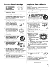
... of at plugs, convenience receptacles, and the point where they exit from overheating and to drapes, curtains, or walls; Never place the TV: • on an unstable cart, stand, or table. Important Safety Instructions 1) Read these instructions. 2) Keep these recommendations and precautions and... next page) 3 Installation, Care, and Service Installation Follow these instructions. 3) Heed all warnings. 4) Follow all servicing to protect the TV from the apparatus. 11) Only use attachments/accessories specified by the manufacturer. 12) Use only with the cart, stand, tripod, bracket,...
... of at plugs, convenience receptacles, and the point where they exit from overheating and to drapes, curtains, or walls; Never place the TV: • on an unstable cart, stand, or table. Important Safety Instructions 1) Read these instructions. 2) Keep these recommendations and precautions and... next page) 3 Installation, Care, and Service Installation Follow these instructions. 3) Heed all warnings. 4) Follow all servicing to protect the TV from the apparatus. 11) Only use attachments/accessories specified by the manufacturer. 12) Use only with the cart, stand, tripod, bracket,...

Owner's Manual - English
Page 4
...damage, never strike the glass with , such as window side or outside of LCD technology and is manufactured using only a soft cloth (cotton, flannel, etc.). This is a structural property of the room. 32) LCD (Liquid Crystal Display) may make occasional snapping or popping sounds. Never locate the... when the unit is not a sign of the TV, or follow these sounds become frequent or continuous, unplug the power cord and contact a Toshiba Authorized Service Center. 35) The screen on -screen target may vary until the LCD TV warms up static charges (see Section 810 of your...
...damage, never strike the glass with , such as window side or outside of LCD technology and is manufactured using only a soft cloth (cotton, flannel, etc.). This is a structural property of the room. 32) LCD (Liquid Crystal Display) may make occasional snapping or popping sounds. Never locate the... when the unit is not a sign of the TV, or follow these sounds become frequent or continuous, unplug the power cord and contact a Toshiba Authorized Service Center. 35) The screen on -screen target may vary until the LCD TV warms up static charges (see Section 810 of your...

Owner's Manual - English
Page 5
Introduction 6 Welcome to Toshiba 6 Supplied accessories 6 Note Regarding Quick Connect Guide 6 Exploring your new TV 7 Connecting your TV 8 Connecting a VCR 9 Connecting a cable converter box 9 Connecting a cable converter box and VCR ...42 If you cannot remember your PIN code 42 Using the V-CHIP menu 43 ENABLE BLOCKING 43 TV RATING (Independent rating system for broadcasters 43 MPAA RATING (Independent rating system for movies 44 BLOCKING OPTION... Specifications 61 Troubleshooting 62 Limited United States Warranty for LCD TV 63 Limited Canada Warranty for LCD TV 64 Index 65 5
Introduction 6 Welcome to Toshiba 6 Supplied accessories 6 Note Regarding Quick Connect Guide 6 Exploring your new TV 7 Connecting your TV 8 Connecting a VCR 9 Connecting a cable converter box 9 Connecting a cable converter box and VCR ...42 If you cannot remember your PIN code 42 Using the V-CHIP menu 43 ENABLE BLOCKING 43 TV RATING (Independent rating system for broadcasters 43 MPAA RATING (Independent rating system for movies 44 BLOCKING OPTION... Specifications 61 Troubleshooting 62 Limited United States Warranty for LCD TV 63 Limited Canada Warranty for LCD TV 64 Index 65 5