Installation Instructions
Page 6
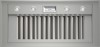
General Information This manual provides the proper installation instructions for two styles of THERMADOR PROFESSIONAL® custom insert hoods: VCINxxJP Overall Dimensions VCINxxJP - 22" (559 mm) in depth and with widths of 33¾" (857 mm), 45¾" (1,162 mm) or 51¾" (1,315 ...¾" (1,315 mm) 25ǩ" (640 mm) 50Ǫ" (1,280 mm) A Rear View C B 12 13/16" (325 mm) 11/16" (17 mm) Table 1: VCIN Custom Insert Overall Dimensions English 4
General Information This manual provides the proper installation instructions for two styles of THERMADOR PROFESSIONAL® custom insert hoods: VCINxxJP Overall Dimensions VCINxxJP - 22" (559 mm) in depth and with widths of 33¾" (857 mm), 45¾" (1,162 mm) or 51¾" (1,315 ...¾" (1,315 mm) 25ǩ" (640 mm) 50Ǫ" (1,280 mm) A Rear View C B 12 13/16" (325 mm) 11/16" (17 mm) Table 1: VCIN Custom Insert Overall Dimensions English 4
Installation Instructions
Page 7
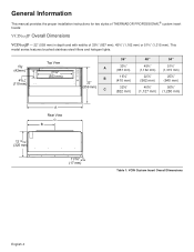
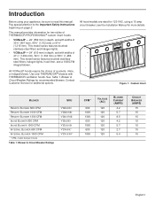
This model series features brushed stainless-steel filters, halogen lights, hood liner, and a 1000CFM integral blower. 15/8" (42mm) 45/16" (110 mm) Top View 21¾" (553 mm) A B 24¾" (629 mm) C 36 po 40½" (1,...) 223/16" (564 mm) 44Ǫ" (1,127 mm) 253/16" (640 mm) 50Ǫ" (1,280 mm) A Rear View C B 14 5/16" (363 mm) Table 2: VCIB Custom Insert Overall Dimensions English 5 VCIBxxJP Overall Dimensions VCIBxxJP - 24" (610 mm) in depth and with widths of 41½" (1,054 mm), 52½" (1,334 mm) or...
This model series features brushed stainless-steel filters, halogen lights, hood liner, and a 1000CFM integral blower. 15/8" (42mm) 45/16" (110 mm) Top View 21¾" (553 mm) A B 24¾" (629 mm) C 36 po 40½" (1,...) 223/16" (564 mm) 44Ǫ" (1,127 mm) 253/16" (640 mm) 50Ǫ" (1,280 mm) A Rear View C B 14 5/16" (363 mm) Table 2: VCIB Custom Insert Overall Dimensions English 5 VCIBxxJP Overall Dimensions VCIBxxJP - 24" (610 mm) in depth and with widths of 41½" (1,054 mm), 52½" (1,334 mm) or...
Installation Instructions
Page 8
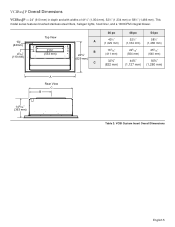
...and structural items. It is operated with a recirculation unit. Hood installation height above a cooktop, rangetop or range, consult the appliance's installation manual. Distance From Cooking Surface The installation height ranges from heat if a THERMADOR PROFESSIONAL® series range or rangetop is the responsibility of ...20 kg) VCIB36JP 96 lb (43.54 kg) VCIB48JP 111 lb (50.35 kg) VCIB54JP 122 lb (55.34 kg) IMPORTANT: The supplied weights address only the ventilation unit and blower. Unit Weight When calculating the load for proper hood height. 30" - 40" (762 - 1,...
...and structural items. It is operated with a recirculation unit. Hood installation height above a cooktop, rangetop or range, consult the appliance's installation manual. Distance From Cooking Surface The installation height ranges from heat if a THERMADOR PROFESSIONAL® series range or rangetop is the responsibility of ...20 kg) VCIB36JP 96 lb (43.54 kg) VCIB48JP 111 lb (50.35 kg) VCIB54JP 122 lb (55.34 kg) IMPORTANT: The supplied weights address only the ventilation unit and blower. Unit Weight When calculating the load for proper hood height. 30" - 40" (762 - 1,...

Installation Instructions
Page 12
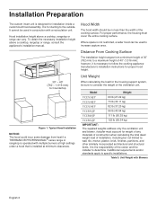
... 11, for Gas Burning Appliances and/or local codes. If there is easy access to a GFCI-protected supply, THERMADOR PROFESSIONAL® custom insert hoods are mounted along the duct line anywhere between the kitchen and the exterior wall. Electrical Data: Data, including the model... close to the appliance as an outdoor covered patio or lanai area). The hood should be connected to relevant regulations. In the U.S., if there are available for THERMADOR PROFESSIONAL® custom insert series hoods. The appliance must be an appealing option. Choosing the Correct Blower A variety...
... 11, for Gas Burning Appliances and/or local codes. If there is easy access to a GFCI-protected supply, THERMADOR PROFESSIONAL® custom insert hoods are mounted along the duct line anywhere between the kitchen and the exterior wall. Electrical Data: Data, including the model... close to the appliance as an outdoor covered patio or lanai area). The hood should be connected to relevant regulations. In the U.S., if there are available for THERMADOR PROFESSIONAL® custom insert series hoods. The appliance must be an appealing option. Choosing the Correct Blower A variety...
Installation Instructions
Page 15
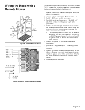
... blower to the connector inside the junction box. 7. Remove junction box channel covering the wires (see the instructions supplied with the blower unit. 1. Wiring the Hood with a Remote Blower 13 5/8" 21/8" (346 mm) (54 mm) 121/8" 21/8" (308 mm) (54 mm) 17/8" (48 mm) 61/2" (165 mm)... 127/8" (327 mm) dia. 97/8" (251 mm) 203/4" 10" (527 mm) (254 mm) 19 7/8" (505 mm) Figure 8: VTR1330E Remote Blower Custom insert models can be replaced with spring type wire nuts, rated for further wiring details. 9. Remove circular knockouts (Figure 5 on chassis. Run five (5) #14 AWG wires...
... blower to the connector inside the junction box. 7. Remove junction box channel covering the wires (see the instructions supplied with the blower unit. 1. Wiring the Hood with a Remote Blower 13 5/8" 21/8" (346 mm) (54 mm) 121/8" 21/8" (308 mm) (54 mm) 17/8" (48 mm) 61/2" (165 mm)... 127/8" (327 mm) dia. 97/8" (251 mm) 203/4" 10" (527 mm) (254 mm) 19 7/8" (505 mm) Figure 8: VTR1330E Remote Blower Custom insert models can be replaced with spring type wire nuts, rated for further wiring details. 9. Remove circular knockouts (Figure 5 on chassis. Run five (5) #14 AWG wires...
Installation Instructions
Page 16
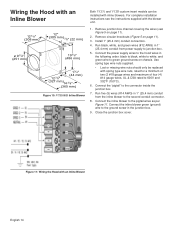
... (327 mm) 14 3/8" (365 mm) Figure 10: VTI1010D Inline Blower 1. Install 1" (25.4 mm) conduit connectors. 4. Connect the power supply wires to the hood wires in 1" (25.4 mm) conduit from power supply to the second conduit connector. 8. Connect the "pigtail" to the pigtail wires as per Figure 11. Remove... wire to the ground screw in 1" (25.4 mm) conduit from the inline blower to junction box. 5. Wiring the Hood with an Inline Blower Both VCIN and VCIB custom insert models can be replaced with spring type wire nuts, rated for a minimum of two (2 #18 gauge wires and maximum...
... (327 mm) 14 3/8" (365 mm) Figure 10: VTI1010D Inline Blower 1. Install 1" (25.4 mm) conduit connectors. 4. Connect the power supply wires to the hood wires in 1" (25.4 mm) conduit from power supply to the second conduit connector. 8. Connect the "pigtail" to the pigtail wires as per Figure 11. Remove... wire to the ground screw in 1" (25.4 mm) conduit from the inline blower to junction box. 5. Wiring the Hood with an Inline Blower Both VCIN and VCIB custom insert models can be replaced with spring type wire nuts, rated for a minimum of two (2 #18 gauge wires and maximum...
Installation Instructions
Page 17
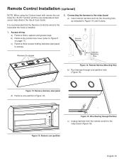
...control to the relay board (Figure 16). Figure 13: Remove core partition English 15 c) Remove three screws holding stainless steel panel to the hood after the hood is installed. 1. It is recommended that the Remote Control be wired to canopy. 2. b) Remove the junction box cover (refer to ...the relay board a) Insert remote harness end into the mounting hole, as indicated in the Use & Care Guide. Access wiring a) Remove filters, spacers and grease ...
...control to the relay board (Figure 16). Figure 13: Remove core partition English 15 c) Remove three screws holding stainless steel panel to the hood after the hood is installed. 1. It is recommended that the Remote Control be wired to canopy. 2. b) Remove the junction box cover (refer to ...the relay board a) Insert remote harness end into the mounting hole, as indicated in the Use & Care Guide. Access wiring a) Remove filters, spacers and grease ...
Installation Instructions
Page 19
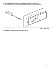
Secure from Figure 12 and Figure 13. 4. Figure 19: Remote Install English 17 Insert remote control into cutout. Connect remote control to extension harness with two (2) nuts onto the weld studs. 6. Reinstall hood components from behind with the included 30 ft (914.4 cm) cable. 5.
Secure from Figure 12 and Figure 13. 4. Figure 19: Remote Install English 17 Insert remote control into cutout. Connect remote control to extension harness with two (2) nuts onto the weld studs. 6. Reinstall hood components from behind with the included 30 ft (914.4 cm) cable. 5.
Installation Instructions
Page 23
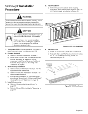
...Refer to the bottom of the housing. Figure 25: VCIN Trim Installation 6. Install the unit a) Install the custom insert inside the custom hood. b) Secure to the hood with backdraft damper so that the flap opens up toward the ceiling. Secure the trim to the rear of the ...If necessary, install thermal break and additional backdraft damper (refer to "Blower Motor Installation" beginning on accidentally. ½" (12.7 mm) x18 CAUTION: The hood weighs at least 60 lbs; b) Refer to "Assembly of the housing framework using six (6) x 2" (50.8 mm) mounting screws, as indicated in...
...Refer to the bottom of the housing. Figure 25: VCIN Trim Installation 6. Install the unit a) Install the custom insert inside the custom hood. b) Secure to the hood with backdraft damper so that the flap opens up toward the ceiling. Secure the trim to the rear of the ...If necessary, install thermal break and additional backdraft damper (refer to "Blower Motor Installation" beginning on accidentally. ½" (12.7 mm) x18 CAUTION: The hood weighs at least 60 lbs; b) Refer to "Assembly of the housing framework using six (6) x 2" (50.8 mm) mounting screws, as indicated in...
Installation Instructions
Page 24
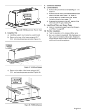
b) Remove circular knock-out holes located on back side of the insert (see blower instructions beginning on page 11). With the blower on page 11). c) Connect wiring for applicable blower motor (see Figure 5 on high, close the ... screws, 3 per side as indicated in the OFF position. English 22 Connect electric a) Remove the junction box cover (see Figure 5 on page 28. 10. Install hood filters, filter spacers, and grease trays a) Refer to ductwork 8. b) Be sure to check for another appliance. Connect to "Installing Grease Trays, Filter Spacers, and Filters...
b) Remove circular knock-out holes located on back side of the insert (see blower instructions beginning on page 11). With the blower on page 11). c) Connect wiring for applicable blower motor (see Figure 5 on high, close the ... screws, 3 per side as indicated in the OFF position. English 22 Connect electric a) Remove the junction box cover (see Figure 5 on page 28. 10. Install hood filters, filter spacers, and grease trays a) Refer to ductwork 8. b) Be sure to check for another appliance. Connect to "Installing Grease Trays, Filter Spacers, and Filters...
Installation Instructions
Page 29
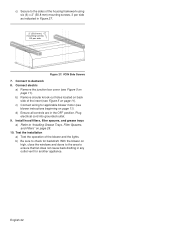
...are in any outlet vent for another appliance. 2" (50.8 mm) X6 mounting screws Figure 37: VCIB Rear Screws c) Secure to the rear of the insert (see Figure 5 on page 28. 10. a) Test the operation of the frame using six (6) 2" (50.8 mm) mounting screws provided (Figure 37...of the blower and the lights. Install the Unit a) Install the custom insert inside the custom hood. c) Connect wiring for backdraft. Connect to "Installing Grease Trays, Filter Spacers, and Filters" on page 11). Install Hood Filters and Grease Trays a) Refer to Ductwork 8. b) Remove circular knock-out...
...are in any outlet vent for another appliance. 2" (50.8 mm) X6 mounting screws Figure 37: VCIB Rear Screws c) Secure to the rear of the insert (see Figure 5 on page 28. 10. a) Test the operation of the frame using six (6) 2" (50.8 mm) mounting screws provided (Figure 37...of the blower and the lights. Install the Unit a) Install the custom insert inside the custom hood. c) Connect wiring for backdraft. Connect to "Installing Grease Trays, Filter Spacers, and Filters" on page 11). Install Hood Filters and Grease Trays a) Refer to Ductwork 8. b) Remove circular knock-out...
Installation Instructions
Page 30
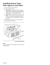
... . push down and in at the bottom. Reverse the above directions to 4 filters per hood. Remove all plastic from 2 or 3 grease trays per hood. 3. c) Filters - Depending upon the size and model of hood, there will be from 2 to remove the grease trays, filter spacers, and filters. ...rangetop burners, elements, or oven while hood is disassembled. Depending upon the size and model of hood, there will be in the following order: a) Grease trays - English 28 b) Filter spacers - The grease trays must be from hood pieces. 2. Insert in place before installing the filters....
... . push down and in at the bottom. Reverse the above directions to 4 filters per hood. Remove all plastic from 2 or 3 grease trays per hood. 3. c) Filters - Depending upon the size and model of hood, there will be from 2 to remove the grease trays, filter spacers, and filters. ...rangetop burners, elements, or oven while hood is disassembled. Depending upon the size and model of hood, there will be in the following order: a) Grease trays - English 28 b) Filter spacers - The grease trays must be from hood pieces. 2. Insert in place before installing the filters....
User Manual
Page 6
...) 15 15 15 15 15 15 15 English 1 Pay special attention to read this manual. This manual provides information for two styles of THERMADOR PROFESSIONAL® custom insert hoods: • VCINxxJP - 22" (559 mm) in depth, and with widths of a remote, inline, or integral blower. See Table ...½" (1,054 mm), 52½" (1,334 mm) or 58½" (1,486 mm). All hood models are rated for more details. Use only THERMADOR® blowers with THERMADOR ventilation hoods. see the Installation Manual for 120 VAC, using your appliance, be sure to the Important Safety Instructions...
...) 15 15 15 15 15 15 15 English 1 Pay special attention to read this manual. This manual provides information for two styles of THERMADOR PROFESSIONAL® custom insert hoods: • VCINxxJP - 22" (559 mm) in depth, and with widths of a remote, inline, or integral blower. See Table ...½" (1,054 mm), 52½" (1,334 mm) or 58½" (1,486 mm). All hood models are rated for more details. Use only THERMADOR® blowers with THERMADOR ventilation hoods. see the Installation Manual for 120 VAC, using your appliance, be sure to the Important Safety Instructions...
User Manual
Page 9
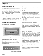
... fan cycles back to reset the 40-hour period and turn off . At the end of the hood. Off Pressing the button once turns the blower off . Figure 2: Custom Insert Control Panel Clean Filter Reminder After 40 hours of heat the control senses. If the blower is on...of the button increases the fan speed until HIGH speed is installed. Operation Operating the Hood For the best results, the blower should be cleaned. HIGH Hood Control Buttons Custom Insert Control Panel Auto (custom insert control panel only) When in order to the Remote Control Installation Instruction for about 5...
... fan cycles back to reset the 40-hour period and turn off . At the end of the hood. Off Pressing the button once turns the blower off . Figure 2: Custom Insert Control Panel Clean Filter Reminder After 40 hours of heat the control senses. If the blower is on...of the button increases the fan speed until HIGH speed is installed. Operation Operating the Hood For the best results, the blower should be cleaned. HIGH Hood Control Buttons Custom Insert Control Panel Auto (custom insert control panel only) When in order to the Remote Control Installation Instruction for about 5...

User Manual
Page 10
... the case of this extreme condition, the three fan speed indicator LEDs will occur. A second press dims the lights. OFF Heat Sensor (custom insert control panel only) Heat sensor feature is disabled if a remote control is turned off . 1 - During reset, the control will be changed ...at 161 °F (72 °C) and reset at 140 °F (60 °C). Over-temperature Condition The high temperature sensor protects the hood from high temperatures which may damage components. Light controls will turn on . English 5 When activated, the blower will remain operational. Lights This button...
... the case of this extreme condition, the three fan speed indicator LEDs will occur. A second press dims the lights. OFF Heat Sensor (custom insert control panel only) Heat sensor feature is disabled if a remote control is turned off . 1 - During reset, the control will be changed ...at 161 °F (72 °C) and reset at 140 °F (60 °C). Over-temperature Condition The high temperature sensor protects the hood from high temperatures which may damage components. Light controls will turn on . English 5 When activated, the blower will remain operational. Lights This button...


