
User Guide
Page 5
TABLE OF CONTENT About This Guide 1 Purpose 1 Terms/Usage 1 Introduction 3 Gigabit Ethernet Technology 3 Fast Ethernet Technology 4 Switching Technology 5 VLAN (Virtual Local Area Network 6 Features 6 Unpacking and Installation 9 Unpacking 9 Installation 9 Rack Mounting 10 Connecting Network Cable 11 AC Power 11 Identifying External Components 13 Front Panel 13 Rear Panel 14 Understanding LED Indicators 15 Power and System LEDs 15 Ports 1~24 Status LEDs 16 Configuration 17 Installing the Web Management Utility 17 i
TABLE OF CONTENT About This Guide 1 Purpose 1 Terms/Usage 1 Introduction 3 Gigabit Ethernet Technology 3 Fast Ethernet Technology 4 Switching Technology 5 VLAN (Virtual Local Area Network 6 Features 6 Unpacking and Installation 9 Unpacking 9 Installation 9 Rack Mounting 10 Connecting Network Cable 11 AC Power 11 Identifying External Components 13 Front Panel 13 Rear Panel 14 Understanding LED Indicators 15 Power and System LEDs 15 Ports 1~24 Status LEDs 16 Configuration 17 Installing the Web Management Utility 17 i

User Guide
Page 9
... in hardware, software, and trained personnel. Gigabit Ethernet Technology Gigabit Ethernet is an extension of IEEE 802.3 Ethernet utilizing the same packet structure, format, and support for CSMA/CD protocol, full duplex, flow control, and management objects, but with all 10-Mbps and 100-Mbps Ethernet environments, Gigabit Ethernet provides a straightforward upgrade without wasting a company's existing investment in the same amount of the 24-Port 10/100/1000Mbps Gigabit Ethernet Web Smart Switch...
... in hardware, software, and trained personnel. Gigabit Ethernet Technology Gigabit Ethernet is an extension of IEEE 802.3 Ethernet utilizing the same packet structure, format, and support for CSMA/CD protocol, full duplex, flow control, and management objects, but with all 10-Mbps and 100-Mbps Ethernet environments, Gigabit Ethernet provides a straightforward upgrade without wasting a company's existing investment in the same amount of the 24-Port 10/100/1000Mbps Gigabit Ethernet Web Smart Switch...
User Guide
Page 11
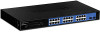
.... A switch bridges Ethernet packets at the MAC address level of local area network congestion problems. 5 Switching is the development of network bridges, which were characterized by dividing a local area network into different segments, which don't compete with any other for network transmission capacity. A switch increases capacity and decreases network loading by higher latencies. Switching LAN technology is multiplied, while still maintaining the same network cabling and adapter...
.... A switch bridges Ethernet packets at the MAC address level of local area network congestion problems. 5 Switching is the development of network bridges, which were characterized by dividing a local area network into different segments, which don't compete with any other for network transmission capacity. A switch increases capacity and decreases network loading by higher latencies. Switching LAN technology is multiplied, while still maintaining the same network cabling and adapter...

User Guide
Page 12
... for Gigabit port Wire speed reception and transmission Store-and-Forward switching scheme capability to support rate adaptation and ensure data integrity Up to 8K unicast addresses entities per device, self-learning, and table aging 6 Other VLAN utility includes: Security, Security is no need to use cross-over cables or an up-link port Full/half duplex transfer mode for 10/100Mbps port Full duplex transfer mode for routers, using VLAN is the one supplied...
... for Gigabit port Wire speed reception and transmission Store-and-Forward switching scheme capability to support rate adaptation and ensure data integrity Up to 8K unicast addresses entities per device, self-learning, and table aging 6 Other VLAN utility includes: Security, Security is no need to use cross-over cables or an up-link port Full/half duplex transfer mode for 10/100Mbps port Full duplex transfer mode for routers, using VLAN is the one supplied...

User Guide
Page 15
... cartons of the Switch and carefully unpacks its performance. When installing, consider the following items: One 24-Port 10/100/1000Mbps Gigabit Ethernet Web Smart Switch One AC power cord, suitable for your local reseller for the acceptable temperature and humidity operating ranges. See Technical Specifications for replacement. The carton should contain the following pointers: Install the Switch in a site free from strong electromagnetic...
... cartons of the Switch and carefully unpacks its performance. When installing, consider the following items: One 24-Port 10/100/1000Mbps Gigabit Ethernet Web Smart Switch One AC power cord, suitable for your local reseller for the acceptable temperature and humidity operating ranges. See Technical Specifications for replacement. The carton should contain the following pointers: Install the Switch in a site free from strong electromagnetic...
User Guide
Page 19
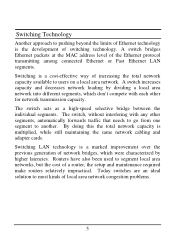
... and play" capability, just need to plug-in half-duplex mode for 10/100/1000Mbps. Note: When the port was set to the hub directly and don't care if the end node is NIC (Network Interface Card) or switch and hub. These ports can operate in the network cable to "Forced Mode", the Auto MDI/MDIX will be disabled. 13 Front Panel The figure below ).
... and play" capability, just need to plug-in half-duplex mode for 10/100/1000Mbps. Note: When the port was set to the hub directly and don't care if the end node is NIC (Network Interface Card) or switch and hub. These ports can operate in the network cable to "Forced Mode", the Auto MDI/MDIX will be disabled. 13 Front Panel The figure below ).

User Guide
Page 21
LED indicators of the Switch Power and System LEDs POWER: Power Indicator On : When the Power LED lights on, the Switch is working . 15 Off : When the Power turns off or the power cord has improper connection. On/Off : The CPU is not working , the System LED is blinking. UNDERSTANDING LED INDICATORS The front panel LEDs provides instant status feedback, and, helps monitor and troubleshoot when needed. SYSTEM: Management Indicator Blinking : When the CPU is receiving power. Figure 5.
LED indicators of the Switch Power and System LEDs POWER: Power Indicator On : When the Power LED lights on, the Switch is working . 15 Off : When the Power turns off or the power cord has improper connection. On/Off : The CPU is not working , the System LED is blinking. UNDERSTANDING LED INDICATORS The front panel LEDs provides instant status feedback, and, helps monitor and troubleshoot when needed. SYSTEM: Management Indicator Blinking : When the CPU is receiving power. Figure 5.
User Guide
Page 23
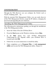
... gives instructions guiding you can configure the Switch such as VLAN, Trunking, QoS... Upon completion, go to install the utility. 5. Follow the on the Windows desktop, choose Run. 3. From the Start menu on -screen instructions to Program Files -> web management utility and execute the Web Management utility. (Figure 6.) 17 CONFIGURATION Through the Web Browser you can easily discover all the Web Management Switch, assign the IP Address, changing the password and upgrading the new firmware...
... gives instructions guiding you can configure the Switch such as VLAN, Trunking, QoS... Upon completion, go to install the utility. 5. Follow the on the Windows desktop, choose Run. 3. From the Start menu on -screen instructions to Program Files -> web management utility and execute the Web Management utility. (Figure 6.) 17 CONFIGURATION Through the Web Browser you can easily discover all the Web Management Switch, assign the IP Address, changing the password and upgrading the new firmware...

User Guide
Page 25
... Name: Shows the device product name. Gateway: Shows the Gateway set of the device. Gateway: Shows the Gateway set of the device. 19 System word definitions in the Monitor List: S: Shows the system symbol of the Web-Smart device, represent for device system is located...Monitor List All the Web Smart Device in the Discovery List: MAC Address: Shows the device MAC Address. Protocol version: Shows the version of the Utility protocol. Trap IP: Shows the IP where the Trap to be sent. IP Address: Shows the current IP address of the device. Subnet Mask: Shows the Subnet Mask set...
... Name: Shows the device product name. Gateway: Shows the Gateway set of the device. Gateway: Shows the Gateway set of the device. 19 System word definitions in the Monitor List: S: Shows the system symbol of the Web-Smart device, represent for device system is located...Monitor List All the Web Smart Device in the Discovery List: MAC Address: Shows the device MAC Address. Protocol version: Shows the version of the Utility protocol. Trap IP: Shows the IP where the Trap to be sent. IP Address: Shows the current IP address of the device. Subnet Mask: Shows the Subnet Mask set...
User Guide
Page 26
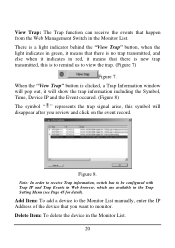
... you review and click on the event record. There is a light indicator behind the "View Trap" button, when the light indicates in green, it means that there is no trap transmitted, and else when it indicates in red, it will show the trap information including the Symbol, Time, Device...to remind us to be configured with Trap IP and Trap Events in Web browser, which are available in the Trap Setting Menu (see Page 45 for detail). Add Item: To add a device to the Monitor List manually, enter the IP Address of the device that happen from the Web Management Switch in the Monitor List. 20
... you review and click on the event record. There is a light indicator behind the "View Trap" button, when the light indicates in green, it means that there is no trap transmitted, and else when it indicates in red, it will show the trap information including the Symbol, Time, Device...to remind us to be configured with Trap IP and Trap Events in Web browser, which are available in the Trap Setting Menu (see Page 45 for detail). Add Item: To add a device to the Monitor List manually, enter the IP Address of the device that happen from the Web Management Switch in the Monitor List. 20

User Guide
Page 27
Select the device in the Device Setting Dialog box. Configuration Setting 21 Device Setting You can set the IP Address, Subnet Mask, Gateway, Set Trap to process the data changed immediately. Figure 9. Configuration Setting: In this button, then the Configuration Setting window will pop out as Figure 9, after filling up the data that you want to change, you can set the device by using the function key in the Discovery list or Monitor List and press this Configuration Setting, you must fill up the password and press the "Set" to (Trap IP Address), System name and Location.
Select the device in the Device Setting Dialog box. Configuration Setting 21 Device Setting You can set the IP Address, Subnet Mask, Gateway, Set Trap to process the data changed immediately. Figure 9. Configuration Setting: In this button, then the Configuration Setting window will pop out as Figure 9, after filling up the data that you want to change, you can set the device by using the function key in the Discovery list or Monitor List and press this Configuration Setting, you must fill up the password and press the "Set" to (Trap IP Address), System name and Location.
User Guide
Page 30
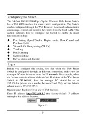
...24 For example, when the default network address of the default IP address of the Web Smart Switch is configured through the Web Browser. A network administrator can be configured through an Ethernet connection, make sure the manager PC must be set on same the IP network. Enter IP address http://192.168.0.1 (the factory-default IP address setting) to enable its smart functions including: Port Setting (Speed/Disable, Duplex mode, Flow Control and Port base QoS) Virtual LAN Group setting (VLAN) Trunking Port Mirroring System Setting Device status and Statistic Login Before you...
...24 For example, when the default network address of the default IP address of the Web Smart Switch is configured through the Web Browser. A network administrator can be configured through an Ethernet connection, make sure the manager PC must be set on same the IP network. Enter IP address http://192.168.0.1 (the factory-default IP address setting) to enable its smart functions including: Port Setting (Speed/Disable, Duplex mode, Flow Control and Port base QoS) Virtual LAN Group setting (VLAN) Trunking Port Mirroring System Setting Device status and Statistic Login Before you...

User Guide
Page 35
... port QoS is high, set to be handling flow control. To add a VLAN group, press "Add Group" button, the new VLAN configuration window will be a member to this VLAN Group, and press "Apply" button to be change. The default setting of the other hardware/software management. When the port is either no flow control or other ports. VLAN Settings (Virtual Local Area Network) Group individual ports into a small "Virtual" network of transferring data. Set FlowCtrl to Disable; Figure 19. Speed/Disable: This setting has six modes...
... port QoS is high, set to be handling flow control. To add a VLAN group, press "Add Group" button, the new VLAN configuration window will be a member to this VLAN Group, and press "Apply" button to be change. The default setting of the other hardware/software management. When the port is either no flow control or other ports. VLAN Settings (Virtual Local Area Network) Group individual ports into a small "Virtual" network of transferring data. Set FlowCtrl to Disable; Figure 19. Speed/Disable: This setting has six modes...

User Guide
Page 37
... of monitoring network traffic that send to the source and forward to copy all packets and a sniffer port where those packets will be studied. Mirror Setting Port Mirroring is as follow: RX (receive) mode: this screen, it if necessary. It enables the manager to renew the posted information. 31 Device Status Click on the "Status" to present the device status on this mode will show the System Status, Port Status, VLAN Status, Trunk Status and Mirror Status..
... of monitoring network traffic that send to the source and forward to copy all packets and a sniffer port where those packets will be studied. Mirror Setting Port Mirroring is as follow: RX (receive) mode: this screen, it if necessary. It enables the manager to renew the posted information. 31 Device Status Click on the "Status" to present the device status on this mode will show the System Status, Port Status, VLAN Status, Trunk Status and Mirror Status..

User Guide
Page 40
... receive data error in copper port. If you forget the password, press the "Reset" button in copper port. Twisted Pair Port Events: Monitoring the copper port status. etc. Abnormal*: 50 error packet count within 10 seconds. Illegal Login: a trap when there is the invaluable tool for the manager to secure Web Management Switch, use this function to be lost and the Switch will be login. Figure 26. Device Bootup: a trap when booting up...
... receive data error in copper port. If you forget the password, press the "Reset" button in copper port. Twisted Pair Port Events: Monitoring the copper port status. etc. Abnormal*: 50 error packet count within 10 seconds. Illegal Login: a trap when there is the invaluable tool for the manager to secure Web Management Switch, use this function to be lost and the Switch will be login. Figure 26. Device Bootup: a trap when booting up...
User Guide
Page 41
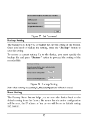
....0.1. 35 Reset Setting The Factory Reset button helps you need to backup the setting, press the "Backup" button to the default setting from the factory. Once you to reset the device back to save the setting. Figure 28. Set Password Backup Setting The backup tools help you must specify the backup file and press "Restore" button to backup the current setting of the device will be reset, the IP address of the Switch. Be aware that the entire configuration will...
....0.1. 35 Reset Setting The Factory Reset button helps you need to backup the setting, press the "Backup" button to the default setting from the factory. Once you to reset the device back to save the setting. Figure 28. Set Password Backup Setting The backup tools help you must specify the backup file and press "Restore" button to backup the current setting of the device will be reset, the IP address of the Switch. Be aware that the entire configuration will...
Quick Installation Guide
Page 3
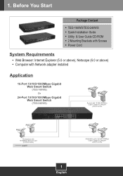
... Start Package Content TEG-160WS/TEG-240WS Quick Installation Guide Utility & User Guide CD-ROM 2 Mounting Brackets with Screws Power Cord System Requirements Web Browser: Internet Explorer (5.0 or above), Netscape (6.0 or above) Computer with Network adapter installed Application 16-Port 10/100/1000Mbps Gigabit Web Smart Switch (TEG-160WS) Or 24-Port 10/100/1000Mbps Gigabit Web Smart Switch (TEG-240WS) Servers with 10/100/1000Mbps Copper Gigabit PCI Adapter (TEG-PCITXR) Workstations with 10/100Mbps Ethernet Card (TE100-PCIWN) gigabit Workstations with...
... Start Package Content TEG-160WS/TEG-240WS Quick Installation Guide Utility & User Guide CD-ROM 2 Mounting Brackets with Screws Power Cord System Requirements Web Browser: Internet Explorer (5.0 or above), Netscape (6.0 or above) Computer with Network adapter installed Application 16-Port 10/100/1000Mbps Gigabit Web Smart Switch (TEG-160WS) Or 24-Port 10/100/1000Mbps Gigabit Web Smart Switch (TEG-240WS) Servers with 10/100/1000Mbps Copper Gigabit PCI Adapter (TEG-PCITXR) Workstations with 10/100Mbps Ethernet Card (TE100-PCIWN) gigabit Workstations with...
Quick Installation Guide
Page 4
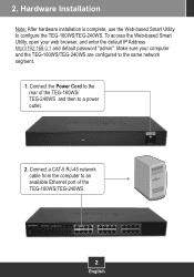
... the default IP Address http://192.168.0.1 and default password "admin". Connect the Power Cord to the rear of the TEG-160WS/TEG-240WS. 2 English 2. To access the Web-based Smart Utility, open your computer and the TEG-160WS/TEG-240WS are configured to a power outlet. 2. Connect a CAT-5 RJ-45 network cable from the computer to configure the TEG-160WS/TEG-240WS. Hardware Installation Note: After hardware installation is complete, use the Web-based Smart Utility to an available Ethernet port of the TEG-160WS/ TEG-240WS...
... the default IP Address http://192.168.0.1 and default password "admin". Connect the Power Cord to the rear of the TEG-160WS/TEG-240WS. 2 English 2. To access the Web-based Smart Utility, open your computer and the TEG-160WS/TEG-240WS are configured to a power outlet. 2. Connect a CAT-5 RJ-45 network cable from the computer to configure the TEG-160WS/TEG-240WS. Hardware Installation Note: After hardware installation is complete, use the Web-based Smart Utility to an available Ethernet port of the TEG-160WS/ TEG-240WS...
Quick Installation Guide
Page 6
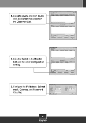
Click Discovery, and then doubleclick the Switch that appears in the Monitor List and then click Configuration setting. 6. Click the Switch in the Discovery List. 5. Click Set. 4 English Configure the IP Address, Subnet mask, Gateway, and Password. 4.
Click Discovery, and then doubleclick the Switch that appears in the Monitor List and then click Configuration setting. 6. Click the Switch in the Discovery List. 5. Click Set. 4 English Configure the IP Address, Subnet mask, Gateway, and Password. 4.
Quick Installation Guide
Page 8
... regarding the TEG-160WS/TEG-240WS, please refer to the User's Guide included on the reset button using a web browser, I do? NOTE: THE MANUFACTURER IS NOT RESPONSIBLE FOR ANY RADIO OR TV INTERFERENCE CAUSED BY UNAUTHORIZED MODIFICATIONS TO THIS EQUIPMENT. SUCH MODIFICATIONS COULD VOID THE USER'S AUTHORITY TO OPERATE THE EQUIPMENT. 6 Q2: After installing the Web-Management Utility, I connect a computer to the Switch's gigabit port, the LINK/ACT LED turns on...
... regarding the TEG-160WS/TEG-240WS, please refer to the User's Guide included on the reset button using a web browser, I do? NOTE: THE MANUFACTURER IS NOT RESPONSIBLE FOR ANY RADIO OR TV INTERFERENCE CAUSED BY UNAUTHORIZED MODIFICATIONS TO THIS EQUIPMENT. SUCH MODIFICATIONS COULD VOID THE USER'S AUTHORITY TO OPERATE THE EQUIPMENT. 6 Q2: After installing the Web-Management Utility, I connect a computer to the Switch's gigabit port, the LINK/ACT LED turns on...


