

T1500-28PCT V1 User Guide
Page 4
... About this Guide...2 1.1 Intended Readers...2 1.2 Conventions...2 1.3 Overview of This Guide 2 Chapter 2 Introduction...6 2.1 Overview of the Switch 6 2.2 Main Features...6 2.3 Appearance Description 7 2.3.1 Front Panel...7 2.3.2 Rear Panel ...9 Chapter 3 Login to the Switch 10 3.1 Login...10 3.2 Configuration...11 Chapter 4 System ...12 4.1 System Info ...12 4.1.1 System Summary 12 4.1.2 Device Description 14...System Reboot 21 4.3.5 System Reset 21 4.4 Access Security ...22 4.4.1 Access Control 22 4.4.2 SSL Config ...23 4.4.3 SSH Config...25 Chapter 5 Switching ...32 5.1 Port...32 III
... About this Guide...2 1.1 Intended Readers...2 1.2 Conventions...2 1.3 Overview of This Guide 2 Chapter 2 Introduction...6 2.1 Overview of the Switch 6 2.2 Main Features...6 2.3 Appearance Description 7 2.3.1 Front Panel...7 2.3.2 Rear Panel ...9 Chapter 3 Login to the Switch 10 3.1 Login...10 3.2 Configuration...11 Chapter 4 System ...12 4.1 System Info ...12 4.1.1 System Summary 12 4.1.2 Device Description 14...System Reboot 21 4.3.5 System Reset 21 4.4 Access Security ...22 4.4.1 Access Control 22 4.4.2 SSL Config ...23 4.4.3 SSH Config...25 Chapter 5 Switching ...32 5.1 Port...32 III

T1500-28PCT V1 User Guide
Page 9
Package Contents The following items should be found in your box: One T1500-28PCT Smart PoE Switch One power cord Two mounting brackets and other fittings Installation Guide Resource CD for T1500-28PCT switch, including: • This User Guide • CLI Reference Guide • SNMP Mibs • Other Helpful Information Note : Make sure that the package contains the above items. If any of the listed items are damaged or missing, please contact your distributor. 1
Package Contents The following items should be found in your box: One T1500-28PCT Smart PoE Switch One power cord Two mounting brackets and other fittings Installation Guide Resource CD for T1500-28PCT switch, including: • This User Guide • CLI Reference Guide • SNMP Mibs • Other Helpful Information Note : Make sure that the package contains the above items. If any of the listed items are damaged or missing, please contact your distributor. 1

T1500-28PCT V1 User Guide
Page 10
...Readers This Guide is located under the System Info menu option that helps you make better use of your device. 1.3 Overview of T1500-28PCT switch. Symbols in this Guide: Symbol De scription Note : Tips: Ignoring this type of note might result in this Guide This... User Guide contains information for setup and management of T1500-28PCT Smart PoE Switch. Chapter 2 Introduction Introduces the features, application and appearance of This Guide Chapte r Introduction Chapter 1 About This Guide Introduces ...
...Readers This Guide is located under the System Info menu option that helps you make better use of your device. 1.3 Overview of T1500-28PCT switch. Symbols in this Guide: Symbol De scription Note : Tips: Ignoring this type of note might result in this Guide This... User Guide contains information for setup and management of T1500-28PCT Smart PoE Switch. Chapter 2 Introduction Introduces the features, application and appearance of This Guide Chapte r Introduction Chapter 1 About This Guide Introduces ...

T1500-28PCT V1 User Guide
Page 11
... Config: Configure and view the global settings of spanning tree function. Port Config: Configure CIST parameters of the switch. Access Security: Provide different security measures for the port. LAG: Configure Link Aggregation Group. Here mainly introduces: Port: Configure the basic features for the login to enhance the configuration...
... Config: Configure and view the global settings of spanning tree function. Port Config: Configure CIST parameters of the switch. Access Security: Provide different security measures for the port. LAG: Configure Link Aggregation Group. Here mainly introduces: Port: Configure the basic features for the login to enhance the configuration...

T1500-28PCT V1 User Guide
Page 12
...SNMP function. Notification: Configure notification function for PoE port to supply power. This module is used system tools to manage the switch. This module is used to assemble the commonly used to configure LLDP function to provide information for SNMP applications to simplify troubleshooting. This module... local device and its effect on a specific port/VLAN. This module is used to configure the PoE function for the switch to supply power for various network applications and requirements. Here mainly introduces: System Monitor: Monitor the memory and CPU of the...
...SNMP function. Notification: Configure notification function for PoE port to supply power. This module is used system tools to manage the switch. This module is used to assemble the commonly used to configure LLDP function to provide information for SNMP applications to simplify troubleshooting. This module... local device and its effect on a specific port/VLAN. This module is used to configure the PoE function for the switch to supply power for various network applications and requirements. Here mainly introduces: System Monitor: Monitor the memory and CPU of the...

T1500-28PCT V1 User Guide
Page 13
Appendix B Configure the PCs Introduces how to CONTENTS 5 Return to configure the PCs. Chapte r Introduction Appendix A Specifications Lists the hardware specifications of the switch. Appendix C Glossary Lists the glossary used in this manual.
Appendix B Configure the PCs Introduces how to CONTENTS 5 Return to configure the PCs. Chapte r Introduction Appendix A Specifications Lists the hardware specifications of the switch. Appendix C Glossary Lists the glossary used in this manual.

T1500-28PCT V1 User Guide
Page 14
... flexible solutions for workgroups and departments, T1500-28PCT from malicious attack or configuration mistakes • Layer 2 Switching + Supports up to 512 VLANs simultaneously (out of 4K VLAN IDs). • Quality of business critical data. Link aggregation (LACP) increase aggregated bandwidth, ...in multiple VLAN environments. + Multicast snooping automatically prevents flooding of IP multicast traffic. + Root Guard protects root bridge from TP-LINK provides wire-speed performance and full set of layer 2 management features. It provides a variety of service features and multiple ...
... flexible solutions for workgroups and departments, T1500-28PCT from malicious attack or configuration mistakes • Layer 2 Switching + Supports up to 512 VLANs simultaneously (out of 4K VLAN IDs). • Quality of business critical data. Link aggregation (LACP) increase aggregated bandwidth, ...in multiple VLAN environments. + Multicast snooping automatically prevents flooding of IP multicast traffic. + Root Guard protects root bridge from TP-LINK provides wire-speed performance and full set of layer 2 management features. It provides a variety of service features and multiple ...
T1500-28PCT V1 User Guide
Page 15
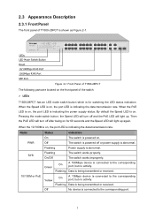
... device is connected to the corresponding port, but no activity. 2.3 Appearance Description 2.3.1 Front Panel The front panel of the switch: LEDs T1500-28PCT has an LED mode switch button which is for 60 seconds and the Speed LED will light up again. When the 10/100M is on, the port... 100Mbps device is connected to the corresponding port, but no activity. When the Speed LED is on the front panel of T1500-28PCT is abnormal. PWR Off The switch is powered off or power supply is indicating the data transmission rate. Data is being transmitted or received. 10/100M or...
... device is connected to the corresponding port, but no activity. 2.3 Appearance Description 2.3.1 Front Panel The front panel of the switch: LEDs T1500-28PCT has an LED mode switch button which is for 60 seconds and the Speed LED will light up again. When the 10/100M is on, the port... 100Mbps device is connected to the corresponding port, but no activity. When the Speed LED is on the front panel of T1500-28PCT is abnormal. PWR Off The switch is powered off or power supply is indicating the data transmission rate. Data is being transmitted or received. 10/100M or...

T1500-28PCT V1 User Guide
Page 16
...is on, the port LED is being transmitted or received. Name PWR SYS PoE MAX 10/100M or PoE 1000M Status Indication On The switch is abnormal. Flashing Power supply is powered on for five seconds or above to reset the software setting back to factory default setting. ... is connected to the corresponding port, but no activity. Yellow On A 10/100Mbps device is connected to the corresponding port. On/Off The switch works improperly. Off No PoE power supply is being transmitted or received. Data is provided on self-test has failed. On The remaining PoE ...
...is on, the port LED is being transmitted or received. Name PWR SYS PoE MAX 10/100M or PoE 1000M Status Indication On The switch is abnormal. Flashing Power supply is powered on for five seconds or above to reset the software setting back to factory default setting. ... is connected to the corresponding port, but no activity. Yellow On A 10/100Mbps device is connected to the corresponding port. On/Off The switch works improperly. Off No PoE power supply is being transmitted or received. Data is provided on self-test has failed. On The remaining PoE ...

T1500-28PCT V1 User Guide
Page 17
...gigabit module. Figure 2-2 Rear Panel of T1500-28PCT features a Kensington security socket, a power socket and a Grounding Terminal (marked with ). Return to install the SFP module. Meanwhile, the associated two ports share the same LED. You can also ground the switch through Telnet. SFP Ports: Designed... to CONTENTS 9 For T1500-28PCT, Port 27 shares the same LED with Port 27F and Port 28 shares the same LED with Lightning...
...gigabit module. Figure 2-2 Rear Panel of T1500-28PCT features a Kensington security socket, a power socket and a Grounding Terminal (marked with ). Return to install the SFP module. Meanwhile, the associated two ports share the same LED. You can also ground the switch through Telnet. SFP Ports: Designed... to CONTENTS 9 For T1500-28PCT, Port 27 shares the same LED with Port 27F and Port 28 shares the same LED with Lightning...

T1500-28PCT V1 User Guide
Page 18
... IP address of your PC should be set in the address field of the switch. Then click the Login button or press the Enter key. The IP address is 192.168.0.x ("x" is any number from 2 to Appendix B. 2) After a moment, a login ...window will appear, as shown in lower case letters. Figure 3-2 Login 10 Chapter 3 Login to the Switch 3.1 Login 1) To access the configuration utility, open a web-browser and type in the default address http://192.168.0.1 in the same subnet addresses of the...
... IP address of your PC should be set in the address field of the switch. Then click the Login button or press the Enter key. The IP address is 192.168.0.x ("x" is any number from 2 to Appendix B. 2) After a moment, a login ...window will appear, as shown in lower case letters. Figure 3-2 Login 10 Chapter 3 Login to the Switch 3.1 Login 1) To access the configuration utility, open a web-browser and type in the default address http://192.168.0.1 in the same subnet addresses of the...

T1500-28PCT V1 User Guide
Page 19
Return to keep the configurations effective even the switch is rebooted. Figure 3-3 Main Setup-Menu Note : Clicking Apply can configure the function by clicking the setup menu on the left side of the screen. You are suggested to click Save Config before the switch is rebooted, please click Save Config. 3.2 Configuration After a successful login, the main page will appear as Figure 3-3, and you want to CONTENTS 11 If you can only make the new configurations effective before cutting off the power or rebooting the switch to avoid losing the new configurations.
Return to keep the configurations effective even the switch is rebooted. Figure 3-3 Main Setup-Menu Note : Clicking Apply can configure the function by clicking the setup menu on the left side of the screen. You are suggested to click Save Config before the switch is rebooted, please click Save Config. 3.2 Configuration After a successful login, the main page will appear as Figure 3-3, and you want to CONTENTS 11 If you can only make the new configurations effective before cutting off the power or rebooting the switch to avoid losing the new configurations.

T1500-28PCT V1 User Guide
Page 20
... 27F and 28F. Indicates the 1000Mbps port is not connected to a device. Indicates the 1000Mbps port is mainly for system configuration of the switch. Chapter 4 System The System module is not connected to a device. The port status diagram shows the working status of 24 10/100Mbps RJ45... ports, 4 10/100/1000Mbps RJ45 ports and 2 SFP ports of the switch, including four submenus: System Info, User M anage, System Tools and Access Security. 4.1 System Info The System Info, mainly for basic properties configuration,...
... 27F and 28F. Indicates the 1000Mbps port is not connected to a device. Indicates the 1000Mbps port is mainly for system configuration of the switch. Chapter 4 System The System module is not connected to a device. The port status diagram shows the working status of 24 10/100Mbps RJ45... ports, 4 10/100/1000Mbps RJ45 ports and 2 SFP ports of the switch, including four submenus: System Info, User M anage, System Tools and Access Security. 4.1 System Info The System Info, mainly for basic properties configuration,...

T1500-28PCT V1 User Guide
Page 21
... transmission rate of the port. Click a port to display the bandwidth utilization of the port. Indicates the SFP port is at the speed of the switch. Indicates the SFP port is at the speed of 10Mbps or 100Mbps. The following figure displays the bandwidth utilization monitored every four seconds. When the...
... transmission rate of the port. Click a port to display the bandwidth utilization of the port. Indicates the SFP port is at the speed of the switch. Indicates the SFP port is at the speed of 10Mbps or 100Mbps. The following figure displays the bandwidth utilization monitored every four seconds. When the...

T1500-28PCT V1 User Guide
Page 22
... 4-5 System Time 14 Enter your contact information. 4.1.3 System Time System Time is the time displayed while the switch is running. Choose the menu System→System Info→Device Description to load the following page. Figure 4-4 Device Description The following ... of sending packets on this screen: Device Description Device Name: Device Location: System Contact: Enter the name of the switch. Enter the location of the switch, including device name, device location and system contact. On this page you can manually set the system time or synchronize with PC...
... 4-5 System Time 14 Enter your contact information. 4.1.3 System Time System Time is the time displayed while the switch is running. Choose the menu System→System Info→Device Description to load the following page. Figure 4-4 Device Description The following ... of sending packets on this screen: Device Description Device Name: Device Location: System Contact: Enter the name of the switch. Enter the location of the switch, including device name, device location and system contact. On this page you can manually set the system time or synchronize with PC...

T1500-28PCT V1 User Guide
Page 23
... PC'S Clock: When this screen: Time Info Current System Date: Displays the current date and time of the switch. Current Time Source: Displays the current time source of the switch. 2. Figure 4-6 Daylight Saving Time 15 The system time will get time from the time server of the Internet if it... has connected to reconfigure the system time of the switch. Time Config M anual: Get Time from NTP Server is selected and no time server is selected, you can set the date and time ...
... PC'S Clock: When this screen: Time Info Current System Date: Displays the current date and time of the switch. Current Time Source: Displays the current time source of the switch. 2. Figure 4-6 Daylight Saving Time 15 The system time will get time from the time server of the Internet if it... has connected to reconfigure the system time of the switch. Time Config M anual: Get Time from NTP Server is selected and no time server is selected, you can set the date and time ...

T1500-28PCT V1 User Guide
Page 24
...Saving Time. You can log on this screen: DST Config DST Status: Enable or disable the DST. Note : 1. The switch supports three modes to operate the switch using a new mode will replace the original IP address. Predefined M ode: Recurring M ode: Date Mode: Select a predefined DST ...Specify the time adding in minutes when Daylight Saving Time comes. Start/End Time: Select starting time and ending time of the switch. 16 Specify the DST configuration in the network possesses a unique IP address. When the DST is enabled, the default daylight saving time ...
...Saving Time. You can log on this screen: DST Config DST Status: Enable or disable the DST. Note : 1. The switch supports three modes to operate the switch using a new mode will replace the original IP address. Predefined M ode: Recurring M ode: Date Mode: Select a predefined DST ...Specify the time adding in minutes when Daylight Saving Time comes. Start/End Time: Select starting time and ending time of the switch. 16 Specify the DST configuration in the network possesses a unique IP address. When the DST is enabled, the default daylight saving time ...

T1500-28PCT V1 User Guide
Page 25
... server; The IP address configured will obtain network parameters from DHCP server until success. 17 However, if another VLAN is created and set to the switch. Choose the menu System→System Info→System IP to a port that is a member of the Management VLAN. Figure 4-7 System IP The ...following page. If the switch gets the IP address from DHCP server, you may have to reconnect the management station to load the following entries are displayed on the...
... server; The IP address configured will obtain network parameters from DHCP server until success. 17 However, if another VLAN is created and set to the switch. Choose the menu System→System Info→System IP to a port that is a member of the Management VLAN. Figure 4-7 System IP The ...following page. If the switch gets the IP address from DHCP server, you may have to reconnect the management station to load the following entries are displayed on the...

T1500-28PCT V1 User Guide
Page 26
... name and password for users to log on to the Web management page with a certain access level so as to protect the settings of the switch from the Internet, which means that IP address, subnet mask and default gateway cannot be implemented on to log on User Table and User Config... pages. 4.2.1 User Table On this page you can configure all the functions of the switch. The switch provides two access levels: Guest and Admin. the admin can configure the access level of the user to the Web management page. Figure 4-8 User...
... name and password for users to log on to the Web management page with a certain access level so as to protect the settings of the switch from the Internet, which means that IP address, subnet mask and default gateway cannot be implemented on to log on User Table and User Config... pages. 4.2.1 User Table On this page you can configure all the functions of the switch. The switch provides two access levels: Guest and Admin. the admin can configure the access level of the user to the Web management page. Figure 4-8 User...

T1500-28PCT V1 User Guide
Page 27
.... Click the Edit button of the desired entry, and you can upload a backup configuration file to restore your switch to login. Admin: Admin can edit, modify and view all the settings of the switch, can be deleted. Access level of the current user information can't be modified. 4.3 System Tools The System...
.... Click the Edit button of the desired entry, and you can upload a backup configuration file to restore your switch to login. Admin: Admin can edit, modify and view all the settings of the switch, can be deleted. Access level of the current user information can't be modified. 4.3 System Tools The System...

