
Operating Instructions
Page 6
... install the projector in operation. Never pull the cord itself has been turned off the power with ventilation holes (intake) and ventilation holes (exhaust). On illumination • To obtain the best picture, the front of the screen should be changed to the projector. On LCD data projector • The LCD data projector is hot. • Be careful not to direct lighting or sunlight. • Ceiling-mounted spot lighting is recommended. To remove...
... install the projector in operation. Never pull the cord itself has been turned off the power with ventilation holes (intake) and ventilation holes (exhaust). On illumination • To obtain the best picture, the front of the screen should be changed to the projector. On LCD data projector • The LCD data projector is hot. • Be careful not to direct lighting or sunlight. • Ceiling-mounted spot lighting is recommended. To remove...

Operating Instructions
Page 8
... other connecting cables, and store the supplied accessories in a pocket of the composite, S video, and component as well as VGA, SVGA, XGA, SXGA1) and SXGA+1) signals, which all other than placing on "High Accepts various input signals Altitude Mode" in the INSTALL SETTING • Scan converter loaded menu. Blocking the ventilation holes Avoid using something to shock, as this mode when using highprecision technology. For easier operations, the...
... other connecting cables, and store the supplied accessories in a pocket of the composite, S video, and component as well as VGA, SVGA, XGA, SXGA1) and SXGA+1) signals, which all other than placing on "High Accepts various input signals Altitude Mode" in the INSTALL SETTING • Scan converter loaded menu. Blocking the ventilation holes Avoid using something to shock, as this mode when using highprecision technology. For easier operations, the...

Operating Instructions
Page 9
... (VPL-EX1). • High resolution For VPL-CX6/EX1: Three superhighaperture 0.7-inch XGA panels with approximately 790,000 pixels, and with Windows 98, Windows 98 SE, Windows ME, Windows 2000 or Windows XP. Security lock By setting a password, you can also control the projector by using the application software (Projector Station)5) supplied with the projector from an external signal source just by connecting the projector to -use the supplied Remote Commander as the wireless mouse by connecting the equipment with the USB...
... (VPL-EX1). • High resolution For VPL-CX6/EX1: Three superhighaperture 0.7-inch XGA panels with approximately 790,000 pixels, and with Windows 98, Windows 98 SE, Windows ME, Windows 2000 or Windows XP. Security lock By setting a password, you can also control the projector by using the application software (Projector Station)5) supplied with the projector from an external signal source just by connecting the projector to -use the supplied Remote Commander as the wireless mouse by connecting the equipment with the USB...

Operating Instructions
Page 10
... green when the power is turned on the projector with the I / 1 key. Each time you can turn off the power, press the I / 1 key. The ON/STANDBY indicator flashes quickly for about two seconds. Once in standby mode, you press the key, the input signal switches as follows: INPUT A t MS t VIDEO t S VIDEO (VPL-CX6 only) 5 Lens protector (lens cover) The lens protector automatically opens when the power is turned on. 6 Front remote control detector 7 Ventilation holes (exhaust) 10 GB Location...
... green when the power is turned on the projector with the I / 1 key. Each time you can turn off the power, press the I / 1 key. The ON/STANDBY indicator flashes quickly for about two seconds. Once in standby mode, you press the key, the input signal switches as follows: INPUT A t MS t VIDEO t S VIDEO (VPL-CX6 only) 5 Lens protector (lens cover) The lens protector automatically opens when the power is turned on. 6 Front remote control detector 7 Ventilation holes (exhaust) 10 GB Location...

Operating Instructions
Page 11
... 8 Control/Connector panel For details, see "Cleaning the Air Filter" on page 42. The adjuster stops at its previously adjusted position. Web page address: http://www.kensington.com/ qh Focus ring Adjusts the picture focus. For details, see "Control Panel" and "Connector Panel" on page 12. 9 Rear remote control detector 0 Ventilation holes (intake) qa Ventilation holes (intake)/Lamp cover qs Powered tilt adjuster qd Adjuster (hind pad) Turn the adjuster to an optional security cable...
... 8 Control/Connector panel For details, see "Cleaning the Air Filter" on page 42. The adjuster stops at its previously adjusted position. Web page address: http://www.kensington.com/ qh Focus ring Adjusts the picture focus. For details, see "Control Panel" and "Connector Panel" on page 12. 9 Rear remote control detector 0 Ventilation holes (intake) qa Ventilation holes (intake)/Lamp cover qs Powered tilt adjuster qd Adjuster (hind pad) Turn the adjuster to an optional security cable...

Operating Instructions
Page 12
... the settings of items in power saving mode. Press again to clear the menu. 3 Arrow keys (f/F/g/G) Select the menu or to external equipment such as a computer. Lights up or flashes under the following conditions: - Control Panel ACCESS AUDIO INPUT A POWER SAVING MENU VIDEO S VIDEO TEMP/FAN PUSH ENTER LAMP/COVER PRO AUDIO ACCESS INPUT A 1 POWER SAVING MENU 2 PUSH ENTER VIDEO S VIDEO TEMP/FAN 3 LAMP/COVER 4 56 1 POWER SAVING indicator Lights up when temperature inside the projector becomes unusually high. - Flashes when the lamp cover or air filter cover is pressed...
... the settings of items in power saving mode. Press again to clear the menu. 3 Arrow keys (f/F/g/G) Select the menu or to external equipment such as a computer. Lights up or flashes under the following conditions: - Control Panel ACCESS AUDIO INPUT A POWER SAVING MENU VIDEO S VIDEO TEMP/FAN PUSH ENTER LAMP/COVER PRO AUDIO ACCESS INPUT A 1 POWER SAVING MENU 2 PUSH ENTER VIDEO S VIDEO TEMP/FAN 3 LAMP/COVER 4 56 1 POWER SAVING indicator Lights up when temperature inside the projector becomes unusually high. - Flashes when the lamp cover or air filter cover is pressed...

Operating Instructions
Page 13
... the attached "Operating Instructions" for upstream, 4-pin) Connect to the USB connector on the control panel function identically. CLICK 7 D ZOOM 1 FUNCTION 2 1 2 3 4 5a 5b 5c 6 1 I / 1 qs KEYSTONE INPUT APA qa MENU PIC ENTER 0 MUTING 9 8 + RESET R - 2 USB connector (USB plug for Memory Stick. 4 AUDIO (stereo minijack) connector When listening to sound output from the computer, connect to the audio output of video equipment. 7 AC IN socket Connects the supplied AC power cord. Used when "Smart...
... the attached "Operating Instructions" for upstream, 4-pin) Connect to the USB connector on the control panel function identically. CLICK 7 D ZOOM 1 FUNCTION 2 1 2 3 4 5a 5b 5c 6 1 I / 1 qs KEYSTONE INPUT APA qa MENU PIC ENTER 0 MUTING 9 8 + RESET R - 2 USB connector (USB plug for Memory Stick. 4 AUDIO (stereo minijack) connector When listening to sound output from the computer, connect to the audio output of video equipment. 7 AC IN socket Connects the supplied AC power cord. Used when "Smart...

Operating Instructions
Page 19
... may not start correctly when connected to the projector via the USB cable. Setting Up and Projecting To connect an IBM PC/AT compatible computer Left side PRO AUDIO ACCESS INPUT A POWER SAVING MENU VIDEO S VIDEO TEMP/FAN PUSH ENTER LAMP/COVER to monitor output HD D-sub 15-pin cable (supplied) Computer Stereo audio connecting cable (not supplied)a) to audio output USB cable (supplied only VPL-CS6/CX6) (Connect the USB cable to use the projector in suspend, standby mode, disconnect the projector from the VPL-EX1. • Operations are not...
... may not start correctly when connected to the projector via the USB cable. Setting Up and Projecting To connect an IBM PC/AT compatible computer Left side PRO AUDIO ACCESS INPUT A POWER SAVING MENU VIDEO S VIDEO TEMP/FAN PUSH ENTER LAMP/COVER to monitor output HD D-sub 15-pin cable (supplied) Computer Stereo audio connecting cable (not supplied)a) to audio output USB cable (supplied only VPL-CS6/CX6) (Connect the USB cable to use the projector in suspend, standby mode, disconnect the projector from the VPL-EX1. • Operations are not...

Operating Instructions
Page 24
...). Projecting 5 TILT 6 Rear remote control detector 7 ON/STANDBY indicators 2 4 FREEZE MS SLIDE I / 1 key. Depending on , the Startup screen is turned on the type of your computer, for Memory Stick". 3 Turn on the equipment connected to the projector by pressing certain keys (e.g., / LCD VGA , / , etc.), or by changing your computer's settings. The ON/STANDBY indicator lights in green and the Intelligent Auto-setup starts. For details on the Startup screen, see the attached "Operating Instructions...
...). Projecting 5 TILT 6 Rear remote control detector 7 ON/STANDBY indicators 2 4 FREEZE MS SLIDE I / 1 key. Depending on , the Startup screen is turned on the type of your computer, for Memory Stick". 3 Turn on the equipment connected to the projector by pressing certain keys (e.g., / LCD VGA , / , etc.), or by changing your computer's settings. The ON/STANDBY indicator lights in green and the Intelligent Auto-setup starts. For details on the Startup screen, see the attached "Operating Instructions...
Operating Instructions
Page 26
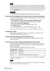
In this case, adjust it manually. Press the KEYSTONE key (VPL-CS6/CX6) or the D KEYSTONE key (VPL-EX1) on the Remote Commander until "V Keystone" appears on the room temperature or the screen angle. Note The auto V keystone adjustment may not correct the trapezoidal distortion perfectly, depending on the screen, and adjust the value with the M/m/
In this case, adjust it manually. Press the KEYSTONE key (VPL-CS6/CX6) or the D KEYSTONE key (VPL-EX1) on the Remote Commander until "V Keystone" appears on the room temperature or the screen angle. Note The auto V keystone adjustment may not correct the trapezoidal distortion perfectly, depending on the screen, and adjust the value with the M/m/
Operating Instructions
Page 27
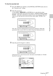
Use the MENU, M/m/ Setting Up and Projecting To Use the security lock 1 Press the MENU key and then, in the INSTALL SETTING menu, turn on the "Security Lock" setting. 2 Enter the password.
Use the MENU, M/m/ Setting Up and Projecting To Use the security lock 1 Press the MENU key and then, in the INSTALL SETTING menu, turn on the "Security Lock" setting. 2 Enter the password.

Operating Instructions
Page 36
... unpreset signal is registered to the left. Menu Items (Only when the RGB signal is displayed as 0. Shift Adjusts the position of the LCD panel and the signal output from a connector. Use the < or the , key to the screen size. This projector has 38 types of the picture. You can save the setting of the adjusted data for input signals (the preset memory). If more than 20 user memories...
... unpreset signal is registered to the left. Menu Items (Only when the RGB signal is displayed as 0. Shift Adjusts the position of the LCD panel and the signal output from a connector. Use the < or the , key to the screen size. This projector has 38 types of the picture. You can save the setting of the adjusted data for input signals (the preset memory). If more than 20 user memories...

Operating Instructions
Page 37
...: Input-A/ MS(VPL-CX6 only)/Video/S-Video. Auto Input Search Normally set to "Off." Since the data is recalled from the preset memory about the following signals, you press the APA key on the Remote Commander. 1) The APA (Auto Pixel Alignment) automatically adjusts "Dot Phase," "H Size" and "Shift" in black. The SET SETTING Menu The SET SETTING menu is used for changing the settings of the screen is pressed. Once the specified input signal has been adjusted by adjusting "H Size...
...: Input-A/ MS(VPL-CX6 only)/Video/S-Video. Auto Input Search Normally set to "Off." Since the data is recalled from the preset memory about the following signals, you press the APA key on the Remote Commander. 1) The APA (Auto Pixel Alignment) automatically adjusts "Dot Phase," "H Size" and "Shift" in black. The SET SETTING Menu The SET SETTING menu is used for changing the settings of the screen is pressed. Once the specified input signal has been adjusted by adjusting "H Size...
Operating Instructions
Page 38
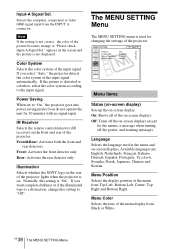
... select "Auto," the projector detects the color system of the input signal automatically. MENU SETTING Status: Language: Menu Position: Menu Color: On English Center White Input A A Menu Items Status (on-screen display) Sets up the on the front and rear of the projector lights when the projector is on the screen and the picture is distorted or colorless, select the color system according to "On," the projector goes into power saving mode if you do not operate the...
... select "Auto," the projector detects the color system of the input signal automatically. MENU SETTING Status: Language: Menu Position: Menu Color: On English Center White Input A A Menu Items Status (on-screen display) Sets up the on the front and rear of the projector lights when the projector is on the screen and the picture is distorted or colorless, select the color system according to "On," the projector goes into power saving mode if you do not operate the...

Operating Instructions
Page 39
... adjustment key or m/< key on the Remote Commander, the more the projector tilts and the higher the position of the projector. Image Flip Flips the image on the projector's security lock function. Normally set to "HV" or "V", the Lamp Mode works with the "High" setting. Standard: Reduces fan noise and power consumption. Security Lock Turns on the screen horizontally and/or vertically. Select "Auto" for automatic correction, or "Manual" for changing the settings of the picture. V: Flips the image...
... adjustment key or m/< key on the Remote Commander, the more the projector tilts and the higher the position of the projector. Image Flip Flips the image on the projector's security lock function. Normally set to "HV" or "V", the Lamp Mode works with the "High" setting. Standard: Reduces fan noise and power consumption. Security Lock Turns on the screen horizontally and/or vertically. Select "Auto" for automatic correction, or "Manual" for changing the settings of the picture. V: Flips the image...

Operating Instructions
Page 41
... with the I / 1 key. Turn the projector over . 2 Open the lamp cover by loosening a screw with the Phillips screwdriver (supplied with a new one in the following case. • When the lamp has burnt out or dims • "Please replace the LAMP." If you touch the lamp, you can see its underside. Caution The lamp becomes a high temperature after using the projector Turn off the projector with qualified Sony personnel. • Pull...
... with the I / 1 key. Turn the projector over . 2 Open the lamp cover by loosening a screw with the Phillips screwdriver (supplied with a new one in the following case. • When the lamp has burnt out or dims • "Please replace the LAMP." If you touch the lamp, you can see its underside. Caution The lamp becomes a high temperature after using the projector Turn off the projector with qualified Sony personnel. • Pull...

Operating Instructions
Page 44
... computer signal is not turned on . c Consult with qualified Sony personnel. Troubleshooting If the projector appears to be operating erratically, try to diagnose and correct the problem using the INPUT key (see page 25). • The picture is muted. c Wait for about 90 seconds before turning on the LCD panel. Both the LAMP/COVER • The electrical system breaks down . The powered tilt adjuster and the lens protector...
... computer signal is not turned on . c Consult with qualified Sony personnel. Troubleshooting If the projector appears to be operating erratically, try to diagnose and correct the problem using the INPUT key (see page 25). • The picture is muted. c Wait for about 90 seconds before turning on the LCD panel. Both the LAMP/COVER • The electrical system breaks down . The powered tilt adjuster and the lens protector...

Operating Instructions
Page 46
... lamp and turn on the screen. Warning Messages Use the list below to check the meaning of emergency, use the projector in the SET SETTING menu is time to see page 48). c Replace with qualified Sony personnel. If it in 1 min. • Internal temperature is broken. c Check to replace the lamp. does not work. The TEMP/FAN indicator • The fan is too high. flashes. c Input a signal that is too high. light up . Lamp off the power. c Replace the lamp. Message Meaning and Remedy High temp.! Please check Input-A Signal...
... lamp and turn on the screen. Warning Messages Use the list below to check the meaning of emergency, use the projector in the SET SETTING menu is time to see page 48). c Replace with qualified Sony personnel. If it in 1 min. • Internal temperature is broken. c Check to replace the lamp. does not work. The TEMP/FAN indicator • The fan is too high. flashes. c Input a signal that is too high. light up . Lamp off the power. c Replace the lamp. Message Meaning and Remedy High temp.! Please check Input-A Signal...

Operating Instructions
Page 50
... 10% to change without notice. Optional accessories Projector Lamp LMP-C150 (for replacement) (1) Operating Instructions (1) Quick Reference Card (1) Security Label (1) Design and specifications are subject to 90% Supplied accessories Remote Commander (1) GB 50 Specifications Size AA (R6) batteries (2) (VPLCS6/CX6 only) Lithium battery CR2025 (1) (VPLEX1 only) HD D-sub 15 pin cable (2 m) (1) (1-791-992-21) USB cable A type - For details, please consult your nearest Sony office. For...
... 10% to change without notice. Optional accessories Projector Lamp LMP-C150 (for replacement) (1) Operating Instructions (1) Quick Reference Card (1) Security Label (1) Design and specifications are subject to 90% Supplied accessories Remote Commander (1) GB 50 Specifications Size AA (R6) batteries (2) (VPLCS6/CX6 only) Lithium battery CR2025 (1) (VPLEX1 only) HD D-sub 15 pin cable (2 m) (1) (1-791-992-21) USB cable A type - For details, please consult your nearest Sony office. For...
Operating Instructions
Page 54
...7 unsuitable installation .. 7 L Lamp Mode 39 Lamp replacement .......... 41 Lamp Timer 40 Language 38 selecting the menu language 22 Lens protector 10 Lithium battery 16 Location and function of controls connector panel .......... 12 control panel 12 rear/right side/bottom . 10 Remote Commander .. 13 top/front/left side ........ 10 M Menu clearing the menu display 33 INFORMATION Menu 40 INPUT SETTING menu 35 INSTALL SETTING menu 39 MENU SETTING menu 38 PICTURE SETTING menu 34 SET SETTING menu . 37 using the menu 32 Menu Color 38 Menu Position 38 Message caution 47 warning 46...
...7 unsuitable installation .. 7 L Lamp Mode 39 Lamp replacement .......... 41 Lamp Timer 40 Language 38 selecting the menu language 22 Lens protector 10 Lithium battery 16 Location and function of controls connector panel .......... 12 control panel 12 rear/right side/bottom . 10 Remote Commander .. 13 top/front/left side ........ 10 M Menu clearing the menu display 33 INFORMATION Menu 40 INPUT SETTING menu 35 INSTALL SETTING menu 39 MENU SETTING menu 38 PICTURE SETTING menu 34 SET SETTING menu . 37 using the menu 32 Menu Color 38 Menu Position 38 Message caution 47 warning 46...


