
User Guide
Page 11
...your computer may vary from those shown in this illustration, based on your computer. Back panel 1 AC Input port Connection for the supplied power cord. 2 Mouse port Connection for a PS/2® mouse. 3 Keyboard port Connection for a PS/2 keyboard. 4 Printer port ...Connection for details on hardware configuration. See your computer contains the ports for supplied and optional accessories. Page 11 About the Back Panel The back panel of your computer's specification sheet for a parallel device, such as...
...your computer may vary from those shown in this illustration, based on your computer. Back panel 1 AC Input port Connection for the supplied power cord. 2 Mouse port Connection for a PS/2® mouse. 3 Keyboard port Connection for a PS/2 keyboard. 4 Printer port ...Connection for details on hardware configuration. See your computer contains the ports for supplied and optional accessories. Page 11 About the Back Panel The back panel of your computer's specification sheet for a parallel device, such as...
User Guide
Page 16
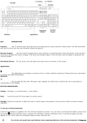
Directional Arrows The up a wireless keyboard Insert two AA batteries (supplied) into the wireless keyboard as shown. Do not mix old (used to deactivate the numeric keypad. BUTTON DESCRIPTION Volume Increases (+) and decreases (-) the volume. ...this key is equivalent to restore sound. AlwPaaygseu1s6e Windows The key with each function key may also appear on the screen when the keyboard's battery power becomes low. Standby Places the computer in Stand by clicking (wireless keyboard icon), located in the Windows® taskbar notification area. KEY DESCRIPTION ...
Directional Arrows The up a wireless keyboard Insert two AA batteries (supplied) into the wireless keyboard as shown. Do not mix old (used to deactivate the numeric keypad. BUTTON DESCRIPTION Volume Increases (+) and decreases (-) the volume. ...this key is equivalent to restore sound. AlwPaaygseu1s6e Windows The key with each function key may also appear on the screen when the keyboard's battery power becomes low. Standby Places the computer in Stand by clicking (wireless keyboard icon), located in the Windows® taskbar notification area. KEY DESCRIPTION ...

User Guide
Page 20
... a wireless optical mouse1. Before attempting to enable communication between your computer, see the section, Connecting the Wireless Optical Mouse. Wireless m ouse (Side and bottom ) 1 Power switch Slide power switch to turn the mouse on the LCD screen. 3 Right mouse button Press to scroll up the wireless mouse Page 20 About the Wireless...
... a wireless optical mouse1. Before attempting to enable communication between your computer, see the section, Connecting the Wireless Optical Mouse. Wireless m ouse (Side and bottom ) 1 Power switch Slide power switch to turn the mouse on the LCD screen. 3 Right mouse button Press to scroll up the wireless mouse Page 20 About the Wireless...

User Guide
Page 21
... s heet for extended periods of battery. Always use the same type and manufacture of time, remove the batteries to be replaced. Insert two AA batteries (supplied) into the wireless m ouse If your mouse's battery power level by clicking (wireless mouse icon), located in the wireless mouse.
... s heet for extended periods of battery. Always use the same type and manufacture of time, remove the batteries to be replaced. Insert two AA batteries (supplied) into the wireless m ouse If your mouse's battery power level by clicking (wireless mouse icon), located in the wireless mouse.

User Guide
Page 22
... between your computer, see the section, Connecting the Wireless Optical Mouse. About the Wireless Mouse Your VAIO® computer may be supplied with your VAIO® computer and the wireless mouse. Wireless m ouse (Side and bottom ) 1 Power switch Slide power switch to turn the mouse on the LCD screen. 3 Right mouse button Press to use...
... between your computer, see the section, Connecting the Wireless Optical Mouse. About the Wireless Mouse Your VAIO® computer may be supplied with your VAIO® computer and the wireless mouse. Wireless m ouse (Side and bottom ) 1 Power switch Slide power switch to turn the mouse on the LCD screen. 3 Right mouse button Press to use...

User Guide
Page 23
... and manufacture of time, remove the batteries to be replaced. Page 23 You can damage the mouse. Insert two AA batteries (supplied) into the wireless m ouse If your mouse's battery power level by clicking (wireless mouse icon), located in the wireless mouse. Using incompatible batteries or mixing used ) and new batteries when...
... and manufacture of time, remove the batteries to be replaced. Page 23 You can damage the mouse. Insert two AA batteries (supplied) into the wireless m ouse If your mouse's battery power level by clicking (wireless mouse icon), located in the wireless mouse. Using incompatible batteries or mixing used ) and new batteries when...

User Guide
Page 28
or 6-pin i.LINK port on your computer. About the i.LINK Port Your VAIO® computer is equipped with a 6-pin connector. The total power supplied by the 6-pin i.LINK port does not exceed 6 watts. Page 28 Connecting an i.LINK (IEEE 1394) device 1. Plug the other end of... the cable into this port. 2. See the instructions supplied with a 4-pin and a 6-pin i.LINK® port. A 6-pin i.LINK port can supply power (10V to 12V) to a connected i.LINK device. Plug the i.LINK cable connector into the corresponding 4- Use the symbol...
or 6-pin i.LINK port on your computer. About the i.LINK Port Your VAIO® computer is equipped with a 6-pin connector. The total power supplied by the 6-pin i.LINK port does not exceed 6 watts. Page 28 Connecting an i.LINK (IEEE 1394) device 1. Plug the other end of... the cable into this port. 2. See the instructions supplied with a 4-pin and a 6-pin i.LINK® port. A 6-pin i.LINK port can supply power (10V to 12V) to a connected i.LINK device. Plug the i.LINK cable connector into the corresponding 4- Use the symbol...

User Guide
Page 35
Turn the wireless mouse over and slide the power button to connect the wireless mouse, confirm that the AA batteries (supplied) are properly installed. Press the CONNECT button located on the bottom of the radio frequency receiver first, and then press the CONNECT button... the CONNECT button, located on the bottom of the mouse. Connecting the Wireless Optical Mouse Your VAIO® computer may be within 2 feet of the VAIO® computer. Confirm that the supplied AA batteries are properly inserted into the mouse before your computer is free of obstructions that may prevent...
Turn the wireless mouse over and slide the power button to connect the wireless mouse, confirm that the AA batteries (supplied) are properly installed. Press the CONNECT button located on the bottom of the radio frequency receiver first, and then press the CONNECT button... the CONNECT button, located on the bottom of the mouse. Connecting the Wireless Optical Mouse Your VAIO® computer may be within 2 feet of the VAIO® computer. Confirm that the supplied AA batteries are properly inserted into the mouse before your computer is free of obstructions that may prevent...

User Guide
Page 67
Page 67 Reconnect the power cord and all peripheral devices. 9. Turn on card. 7. See Replacing the cover. 8. 6. Replace the side cover. See the instructions supplied with the add-on the computer. Attach any internal cables that the card requires.
Page 67 Reconnect the power cord and all peripheral devices. 9. Turn on card. 7. See Replacing the cover. 8. 6. Replace the side cover. See the instructions supplied with the add-on the computer. Attach any internal cables that the card requires.

User Guide
Page 72
...the chassis and slide the drive holder in your new drive as a slave, using the configuration instructions supplied with screws. Do not overtighten these screws when securing the new drive to the holes in the drive ...drive to the drive holder with the drive. 5. Attaching the driv e screws Your new hard disk drive is supplied with the tracks on your computer. 6. See Removing the side cover. 4. Realign the drive holder with the ... drive holder, aligning the holes on its side. Detach the power and drive cables from the chassis by removing the drive holder screw(s). 7.
...the chassis and slide the drive holder in your new drive as a slave, using the configuration instructions supplied with screws. Do not overtighten these screws when securing the new drive to the holes in the drive ...drive to the drive holder with the drive. 5. Attaching the driv e screws Your new hard disk drive is supplied with the tracks on your computer. 6. See Removing the side cover. 4. Realign the drive holder with the ... drive holder, aligning the holes on its side. Detach the power and drive cables from the chassis by removing the drive holder screw(s). 7.
User Guide
Page 73
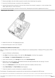
...cable with memory c ard readers . Follow the wizard's on to the new drive, following the instructions supplied with red marking). Page 73 Reconnect the IDE and power connectors to Storage and then select Disk Management. 5. Under the file directory, go to the original ...s heet for more information about your computer. Replace the side cover. A shortcut menu appears. 3. The New Partition wizard appears. 8. Reconnect the power cord to complete the process. Log on -screen instructions to your c omputer's hardware c onfiguration. From the shortcut menu, select Initialize Disk. ...
...cable with memory c ard readers . Follow the wizard's on to the new drive, following the instructions supplied with red marking). Page 73 Reconnect the IDE and power connectors to Storage and then select Disk Management. 5. Under the file directory, go to the original ...s heet for more information about your computer. Replace the side cover. A shortcut menu appears. 3. The New Partition wizard appears. 8. Reconnect the power cord to complete the process. Log on -screen instructions to your c omputer's hardware c onfiguration. From the shortcut menu, select Initialize Disk. ...

User Guide
Page 75
...in an optical drive (unless you plugged the computer into a power strip or Uninterruptible Power Supply (UPS), make sure the power strip or UPS is turned on and working. Verify that the monitor is plugged into an appropriate power source and that the computer is turned on. ... c an purc has e this equipment s eparately. About VAIO Computer Functions My computer does not start. Verify that the computer is plugged into a power source and that it is plugged into a power source and turned on. Check that the power indicator is lit on the front panel of the computer. ...
...in an optical drive (unless you plugged the computer into a power strip or Uninterruptible Power Supply (UPS), make sure the power strip or UPS is turned on and working. Verify that the monitor is plugged into an appropriate power source and that the computer is turned on. ... c an purc has e this equipment s eparately. About VAIO Computer Functions My computer does not start. Verify that the computer is plugged into a power source and that it is plugged into a power source and turned on. Check that the power indicator is lit on the front panel of the computer. ...

User Guide
Page 76
... drive (unless you plugged the computer into a power strip or Uninterruptible Power Supply (UPS), make sure the power strip or UPS is turned on and working. Verify that the monitor is plugged into a power source and turned on. Y ou c an purc has e this equipment s eparately. About VAIO Computer Functions My computer does not start. ...
... drive (unless you plugged the computer into a power strip or Uninterruptible Power Supply (UPS), make sure the power strip or UPS is turned on and working. Verify that the monitor is plugged into a power source and turned on. Y ou c an purc has e this equipment s eparately. About VAIO Computer Functions My computer does not start. ...

User Guide
Page 119
...only. There are no user-serviceable parts in voltage differences that may occur during a brief period of the power supply to handle. Your computer operates on the power cord. Do not operate the computer with a surge protector. This device prevents damage to open the...your computer and its peripheral equipment into the same AC supply line. To avoid personal injury or damage to purchase an Uninterruptible Power Supply (UPS). This protects you may result in the power supply. AC derived from the wall outlet or power strip. Do not place heavy objects on...
...only. There are no user-serviceable parts in voltage differences that may occur during a brief period of the power supply to handle. Your computer operates on the power cord. Do not operate the computer with a surge protector. This device prevents damage to open the...your computer and its peripheral equipment into the same AC supply line. To avoid personal injury or damage to purchase an Uninterruptible Power Supply (UPS). This protects you may result in the power supply. AC derived from the wall outlet or power strip. Do not place heavy objects on...

User Guide
Page 120
... wireless device is free of obstructions that may prevent proper operation. Confirm that the supplied AA batteries are not magnetically shielded Ambient temperature of your Sony computer. Should any problem occurs, unplug your computer, and contact your computer and then... of 2 feet between your VAIO® computer and your wireless device. Verify that any further. Use only specified peripheral equipment and interface cables; Do not use cut or damaged connection cables. Always switch the power off before connecting your computer ...
... wireless device is free of obstructions that may prevent proper operation. Confirm that the supplied AA batteries are not magnetically shielded Ambient temperature of your Sony computer. Should any problem occurs, unplug your computer, and contact your computer and then... of 2 feet between your VAIO® computer and your wireless device. Verify that any further. Use only specified peripheral equipment and interface cables; Do not use cut or damaged connection cables. Always switch the power off before connecting your computer ...


